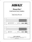
1
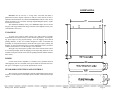
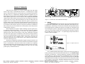
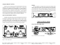
ASHLY
SPECIFICATIONS
P70-400
Output Power
EIA Spec.
(±1dB <1% THD @ 1KHz)
Both Channels Driven
Dual
Bridged-Mono
FTC Spec.
(<.1%THD 20Hz-20KHz)
Both Channels Driven
Dual
Bridge-Mono
Total Harmonic
Distortion
(at rated power)
20Hz-1KHz
20KHz
IM Distortion
(at rated power)
Damping Factor (25Ω)
Bandwidth (-3dB)
Slew Rate
Frequency Response
(20Hz-20KHz)
Full Power Input Sensitivity
Input Impedance
Hum and Noise
(20Hz-20KHz unweighted)
Cooling
Power Requirement
Size
Shipping Weight
P70-800
70 VOLT POWER AMPLIFIERS
Models P70-400, P70-800
200W @ 70V
400W @ 140V
400W @ 70V
800W @ 140V
160W @ 70V
320W @ 140V
320W @ 70V
640W @ 140V
<.05%
.< .1%
<.05%
< .1%
< .05%
< .05%
>500 20Hz-1KHz
100KHz
>20V/µS
+0/-.4dB
>500 20Hz-1KHz
100KHz
>20V/µS
+0/-.4dB
TABLE OF CONTENTS
Introduction ..................................................................... 1
Standard Connections and Controls ................................ 2
Typical Applications ....................................................... 5
Input Options ................................................................... 7
Transformer Input Option ................................................ 7
Limiter Input Option ........................................................ 7
Crossover Input Option ................................................... 8
Mic/Line Mixer Input Option ......................................... 8
Design Theory ................................................................. 10
Dimensional Diagrams ..................................................... 11
Specifications .................................................................. 12
INTRODUCTION . . . Why MOSFETS?
1.77V
1.77V
20KΩBalanced 20KΩBalanced
>105dBbelowfulloutput
>105dBbelowfulloutput
ForcedAir
790WMax,75WIdle
120VAC 50-60Hz
(240V available)
ForcedAir
1580WMax,150WIdle
120VAC 50-60Hz
(240V available)
19"Wx3.5"Hx17.8"D
44 lbs.
60 lbs.
19"Wx3.5"Hx17.8"D
The Ashly P70 series MOSFET amplifiers combine the sonic excellence of
a high-end stereo amp with the ruggedness and stamina necessary in commercial
audio. The P70 series amps use power MOSFETs (metal-oxide-semiconductor,
field-effect transistors) for their superior audio fidelity and unmatched reliability
as proven in Ashly amps for over ten years.
MOSFET output devices are used in the P70 series amps because of their
superior performance characteristics over bipolar power transistors which are
normally used in conventional power amp designs. The power MOSFET is
inherently more self-regulating and does not exhibit the failure modes that bipolar
transistors are susceptible to. MOSFETS do not require any thermal runaway
compensation circuitry, thus making the design simpler and more reliable. MOSFETS do not exhibit secondary breakdown (an instantaneous failure in bipolar
transistors when their collector current exceeds a safe level, even at voltages much
lower than their maximum rating). The MOSFET will even withstand a dead shorted
output resulting in very high drain current without any protection circuitry for a very
short time.
○ ○ ○ ○ ○ ○ ○ ○ ○ ○ ○ ○ ○ ○ ○ ○ ○ ○ ○ ○ ○ ○ ○ ○ ○ ○ ○ ○ ○ ○ ○ ○ ○ ○ ○ ○ ○ ○ ○ ○ ○ ○ ○ ○ ○ ○ ○ ○ ○ ○ ○ ○ ○ ○ ○ ○ ○ ○ ○ ○ ○ ○ ○ ○ ○ ○ ○ ○ ○ ○ ○ ○ ○ ○ ○ ○ ○ ○ ○ ○ ○ ○ ○ ○ ○ ○ ○ ○ ○ ○ ○
Ashly P70 Owners Manual
Page 12
Ashly P70 Owners Manual
Page 1
DIMENSIONS
MOSFETS also do not have a “storage time” associated with them (a
phenomenon found in bipolar transistors in which a certain amount of time is
required to turn the transistor off). Therefore the MOSFET is said to be a “fast” device
which can function very accurately with high amplitude/high frequency signals
and transient waveforms.
The unmatched reliability of the power MOSFET output devices and the
integrity of the rugged mechanical design of the P70 series amplifiers ensure years
of maintenance-free service.
UNPACKING
As a part of our system of quality control, every Ashly product is carefully
inspected before leaving the factory to ensure flawless appearance. After unpacking, please inspect for any physical damage. Save the shipping carton and all
packing materials, as they were carefully designed to reduce to minimum the
possibility of transportation damage should the unit again require packing and
shipping. In the event that damage has occurred, immediately notify your dealer
so that a written claim to cover the damages can be initiated.
The right to any claim against a public carrier can be forfeited if the carrier
is not notified promptly and if the shipping carton and packing materials are not
available for inspection by the carrier. Save all packing materials until the claim has
been settled.
POWER
Connect the P70 series amplifier to a standard 3-wire grounded electrical
outlet supplying 120 volts, 50-60 Hz (some export models are wired for 240 volts).
The power consumption is given in the Specifications section.
STANDARD CONNECTIONS AND CONTROLS
The rear panel of a P70-800 amplifier with the standard input panel is shown
in figure 1. For descriptions of other input options available, see the section on input
options.
○ ○ ○ ○ ○ ○ ○ ○ ○ ○ ○ ○ ○ ○ ○ ○ ○ ○ ○ ○ ○ ○ ○ ○ ○ ○ ○ ○ ○ ○ ○ ○ ○ ○ ○ ○ ○ ○ ○ ○ ○ ○ ○ ○ ○ ○ ○ ○ ○ ○ ○ ○ ○ ○ ○ ○ ○ ○ ○ ○ ○ ○ ○ ○ ○ ○ ○ ○ ○ ○ ○ ○ ○ ○ ○ ○ ○ ○ ○ ○ ○ ○ ○ ○ ○ ○ ○ ○ ○ ○ ○
Ashly P70 Owners Manual
Page 2
Ashly P70 Owners Manual
Page 11
DESIGN THEORY
Ashly P70 series amplifiers use a direct-coupled output stage with totally
discrete high-voltage, wide bandwidth electronics. A modulated power supply
improves output device efficiency, allowing more power with less heat dissipation.
The input section is a complimentary Darlington differential amplifier stage for
high common-mode rejection, low noise and low distortion. All voltage gain stages
in the amplifier operate class A for low distortion. The complimentary MOSFET
output stage has almost infinite current gain, therefore the output driver stages are
nearly lossless. All circuitry within the feedback loop is discrete which allows the
amplifier to recover instantly and cleanly without any spikes or glitches from a
clipped condition. This overall design approach inherently assures low noise, low
distortion, and excellent transient and overload response. Inputs are bridging and
active balanced, and all input connections can operate as balanced or unbalanced.
Turn-on delay relays are not needed because of the symmetry of the totally discrete
complementary electronics.
The P70 amplifiers incorporate output VI limiting to protect against excessive current at the speaker terminals. If current becomes too high, the amplifier
instantaneously reduces output voltage to a safe level. This protects against low
impedance loads, a short across the outputs, as well as DC. Additionally, an internal
fuse follows the output signal of each channel. Under normal operating conditions
however, the VI limiter handles any fault condition at the output. A blown fuse will
only occur in the rare event of amplifier failure. All electronic components are
mounted to rugged glass-epoxy circuit boards. Large computer-grade electrolytic
capacitors assure long service.
The P70 series amplifiers are packaged in a rugged 16-gauge steel chassis. The
power transformer is located at the front center of the chassis to minimize front panel
torsion. Each channel’s electronics and heat sink are identical yet completely
independent and modular, each with a single plug-in connector for ease of servicing.
Large custom black-anodized extruded aluminum heat sinks with fan cooling
provide plenty of thermal headroom.
○ ○ ○ ○ ○ ○ ○ ○ ○ ○ ○ ○ ○ ○ ○ ○ ○ ○ ○ ○ ○ ○ ○ ○ ○ ○ ○ ○ ○ ○ ○ ○ ○ ○ ○ ○ ○ ○ ○ ○ ○ ○ ○ ○ ○ ○ ○ ○ ○
Ashly P70 Owners Manual
Page 10
Figure 1: P70-400 Rear Panel With Standard Input
1. INPUTS
The standard input panel of the P70 series amps is equipped with balanced 1/
4" tip-ring-sleeve (TRS) phone jacks, balanced XLR jacks, and balanced screwterminal inputs. The three types of connectors are internally wired in parallel and may
be used with balanced or unbalanced connections. The inputs are configured for pin
2 hot, meaning that a positive voltage applied to pin 2 will result in a positive output
voltage across the speaker terminals. Pin 2 of the XLR jack is equivalent to the tip of
the 1/4" TRS jack as shown in figure 1. An optional plug-in input transformer is
available on all P70 amplifiers.
Figure 2: Input Connectors
It is recommended that balanced input connections be used when possible to
reduce ground-loop and environment-induced hum and noise. If an unbalanced input
connection is used, then the (-) connection (XLR pin 3) should be connected to input
ground ( XLR pin 1). If the 1/4" input jack is used unbalanced, the use of a mono (tipsleeve) plug will automatically tie the (-) connection to input ground. The CHASSIS
GROUND terminal is internally connected to the chassis, the AC earth ground, and the
p ower amplifier’s signal ground. The INPUT GROUND terminal is tied to the XLR
○pin
○ ○1 ○and
○ ○the
○ ○1/4"
○ ○jack
○ ○ sleeve.
○ ○ ○ ○ ○ ○ ○ ○ ○ ○ ○ ○ ○ ○ ○ ○ ○ ○ ○ ○ ○ ○ ○ ○ ○ ○ ○ ○ ○ ○
Ashly P70 Owners Manual
Page 3
It is recommended that the input and chassis ground terminals remain connected
with the factory-supplied jumper strap.
In situations where the power amp and its signal source are separated by great
distances, a ground voltage difference may exist between the amp’s chassis ground and
the input cable’s ground. Connection of these two grounds through the jumper strap
may cause large ground currents to flow (which is known as a ground loop), causing
a hum noise in the amp’s output. Unless you have such a situation with a hum problem
that cannot be solved by using balanced input connections, the ground jumper strap
should remain in place.
2. NORMAL/BRIDGING SWITCH
This switch selects between NORMAL mode (70 Volt) in the “out” position
where both channels are in-phase, and BRIDGING mode (140 Volt) in the “in” position
where channel 2 is switched out-of-phase. In bridging mode, the channel 1 output
terminal is the (+) in-phase speaker output terminal and the channel 2 output terminal
becomes the (-) out-of-phase speaker terminal. To make the switch non-accessible, its
gray button is removable by simply pulling it straight off.
Figure 8: Crossover Input Option
3. STEREO/MONO SWITCH
This switch selects between STEREO mode in the “out” position and MONO
mode (where channel 1 input is routed to both channels of the amp) in the “in” position.
In mono mode, an input signal needs only to be connected to channel 1. To make the
switch non-accessible, its gray button is removable by simply pulling it straight off.
4. LEVEL CONTROLS
The level controls allow attenuation (calibrated in dB) of the input signal. In
MONO mode, the CHANNEL ONE level control affects both output levels and
CHANNEL TWO level control is unused. It is recommended that the level controls
be operated at full level (0 dB attenuation) in most situations to maximize the headroom
in the signal source.
5. SPEAKER OUTPUTS
A four terminal barrier strip provides the two channels of output. In BRIDGING
mode (140 Volt), the channel 1 output terminal is the (+) in-phase speaker connection
and the channel 2 output terminal becomes the (-) out-of-phase speaker connection.
CAUTION! NEVERCONNECT THE TWOOUTPUT TERMINALSTOGETHER
OR CONNECT EITHER OUTPUT TERMINAL TO COMMON. To prevent
electric shock, always replace the barrier strip protective cover before applying power
to the amplifier.
Figure 9: Mic/Line Mixer Input Option
○ ○ ○ ○ ○ ○ ○ ○ ○ ○ ○ ○ ○ ○ ○ ○ ○ ○ ○ ○ ○ ○ ○ ○ ○ ○ ○ ○ ○ ○ ○ ○ ○ ○ ○ ○ ○ ○ ○ ○ ○ ○ ○ ○ ○ ○ ○ ○ ○ ○ ○ ○ ○ ○ ○ ○ ○ ○ ○ ○ ○ ○ ○ ○ ○ ○ ○ ○ ○ ○ ○ ○ ○ ○ ○ ○ ○ ○ ○ ○ ○ ○ ○ ○ ○ ○ ○ ○ ○ ○ ○
Ashly P70 Owners Manual
Page 4
Ashly P70 Owners Manual
Page 9
CROSSOVER INPUT OPTION
METERS
The XR-1 crossover input option provides separate high-pass and low-pass
24 dB/octave filters allowing flexibility in biamped systems. Output mode
switching allows the amplifier to be configured normal two-way, full range with low
out, mono low out with aux high out, and bridged low out with aux high out.
Included with the XR-1 are single in-line package (SIP) resistor networks which
allow preselection of three standard crossover frequencies. A phase alignment
control and switch are provided for acoustical alignment of high frequency drivers,
and two types of CD horn EQ are available. A third-order 20Hz low-cut filter
removes inaudible subsonic signals from the low frequency signal path.
The P70 amplifiers are equipped with front panel meter displays which
respond to peak output voltage. An eleven-segment, three-color LED display
covers a 27 dB range. The green LED’s at the left end of the meter arrays indicate
a normal thermal status. In the event that the amplifier overheats, these LED’s will
turn off but the power switch will remain illuminated, indicating the thermal
protection status. When the heat sinks return to safe operating temperatures, the amp
will turn itself back on and illuminate the left-most green LED’s.
MIC/LINE MIXER INPUT OPTION
The MM-6 mixer input option provides four high-impedance line inputs and
two balanced low-impedance microphone inputs, each with its own level control.
A switchable 200 Hz high-pass filter is provided on the mic inputs to reduce
unwanted low frequency noise. An internal jumper allows selection of phantom
power applied to the mic inputs for use with condenser mics. The MM-6 has a master
level control and selectable stereo, mono and bridging modes. Insert Points are
available for patching external processing into the left and right channels.
figure 3: P70-400 Front Panel
TYPICALAPPLICATIONS
DUAL CHANNEL OPERATION
Figure 4: Operation in Two Channel Mode
Figure 7: Limiter Input Option
○ ○ ○ ○ ○ ○ ○ ○ ○ ○ ○ ○ ○ ○ ○ ○ ○ ○ ○ ○ ○ ○ ○ ○ ○ ○ ○ ○ ○ ○ ○ ○ ○ ○ ○ ○ ○ ○ ○ ○ ○ ○ ○ ○ ○ ○ ○ ○ ○ ○ ○ ○ ○ ○ ○ ○ ○ ○ ○ ○ ○ ○ ○ ○ ○ ○ ○ ○ ○ ○ ○ ○ ○ ○ ○ ○ ○ ○ ○ ○ ○ ○ ○ ○ ○ ○ ○ ○ ○ ○ ○
Ashly P70 Owners Manual
Page 8
Ashly P70 Owners Manual
Page 5
MONO OPERATION
Figure 5: Operation in Normal Mono Mode
With the MONO switch depressed, the channel 1 input is routed to both
amplifier channels. Both channels are then controlled by the channel 1 level
control. Both outputs will be identical and can be connected to separate speaker
lines. If you wish to drive both channels of the amp with one signal and yet maintain
seperate level control, simply run the amp in stereo mode and hardwire channel one
input to channel two input on the terminal strip. CAUTION! NEVER CONNECT
THE OUTPUT TERMINALS TOGETHER!
BRIDGING OPERATION (140 Volt)
out-of-phase. The channel 1 output terminal is used as the positive and the
channel 2 output terminal becomes the negative. The COMMON terminals are not
used. CAUTION! NEVER GROUND EITHER OUTPUT TERMINAL.
In bridging mode, the output voltage is doubled from 70V to 140V. ONLY
USE 140V STEP-DOWN TRANSFORMERS WHEN RUNNING IN BRIDGED
MONO. If you attempt to use a 70V transformer in this mode, you will have twice
the rated current through the 70V transformer, creating a potential fire hazard. You
will also saturate the core of the transformer, adding distortion to the signal. The
amplifier will become loaded down below the desired point and run hotter than
normal, increasing the likelihood of thermal shut-down.
INPUT OPTIONS
Input option panels are available to provide built-in features such as stereo
limiting, mic and line inputs, crossover for bi-amplified systems, and input
transformers for signal isolation. Ashly P70 series amplifiers as well as all other
Ashly amps (excluding the single rack space SRA-120) will accept Ashly input
options. A brief description of currently stocked input options follows. Consult
your dealer for detailed information on the input options, or call the factory.
TRANSFORMER INPUT OPTION
The ITC-2 transformer input option may be installed in either or both
amplifier channels. The input transformer provides complete electrical isolation
from the amplifier and its signal source to eliminate any ground-induced hum noise,
as well as further reducing any common-mode noise and radio frequency interference. The ITC-2 must be installed in the standard input panel and does not change
the operation of any switches or controls.
LIMITER INPUT OPTION
Figure 6: Operation in Bridging Mode
To operate in bridging mode, depress both the MONO switch and the BRIDGING
switch . The MONO switch depressed routes the channel 1 input to both amplifier
channels and the BRIDGING switch depressed inverts the phase of the input signal
before it is fed to the channel 2 power amp section. The two amplifiers’ outputs are
○ ○ ○ ○ ○180
○ ○degrees
○ ○ ○ ○ ○ ○ ○ ○ ○ ○ ○ ○ ○ ○ ○ ○ ○ ○ ○ ○ ○ ○ ○ ○ ○ ○ ○ ○ ○ ○ ○ ○ ○ ○
therefore
Ashly P70 Owners Manual
Page 6
The CL-2 limiter input option provides peak signal limiting from excessive
input levels for speaker protection and overall level control. Separate recessed
limiter threshold controls, limit indicator LED’s and limit on/off switches are
provided on each channel allowing fully discrete stereo limiting operation.
○ ○ ○ ○ ○ ○ ○ ○ ○ ○ ○ ○ ○ ○ ○ ○ ○ ○ ○ ○ ○ ○ ○ ○ ○ ○ ○ ○ ○ ○ ○ ○ ○ ○ ○ ○ ○ ○ ○ ○ ○ ○ ○ ○ ○ ○ ○ ○ ○ ○
Ashly P70 Owners Manual
Page 7