1
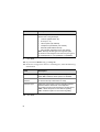
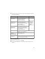
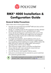
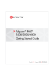
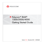
RMX 2000 Installation &
Configuration Guide
General Safety Precautions
Follow these rules to ensure general safety:
•
•
•
•
•
•
•
Keep the area around the Polycom RMX 2000 unit clean and free of
clutter and well ventilated.
Decide on a suitable location for the equipment rack that will hold
the RMX, ensuring that it is near a grounded power outlet.
Ensure that the leveling jacks on the bottom of the rack are fully
extended to the floor with the full weight of the rack resting on
them. Always make sure the rack is stable before extending a
component from the rack.
In a single rack installation, attach stabilizers to the rack. In
multiple rack installations, the racks should be coupled together.
Use a regulating uninterruptable power supply (UPS) to protect the
RMX from power surges and voltage spikes, and to keep it
operating in case of a power failure.
Allow the power supply units to cool before touching them.
Always keep the rack’s trays and board’s closed when not
servicing, to maintain proper cooling.
Preparations
Obtain the following information from your network administrator:
•
•
•
•
IP addresses, Subnet Mask and Default Gateway IP address
(optional) for the RMX control unit and RMX Shelf Management
IP addresses for the RMX Signaling Host and Media Boards
Gatekeeper IP address
SIP server IP address, if applicable
1
Unpacking and Installing the RMX
1
Place the RMX 2000 on a stable flat surface in the selected location.
2
Remove the RMX 2000 from its package. You can install it either in
a rack or place it on a flat surface:
Install the RMX on a rack using one of two methods:
• Install the brackets supplied by the rack manufacturer on
each side of the rack on which the RMX is placed. Secure
the system by fastening four screws to the rack on the
front panel.
• Install a shelf supplied by the rack manufacturer on top of
which the RMX is placed. Secure the system by fastening
four screws to the rack on the front panel.
— Place the RMX 2000 on a secure, flat and clean surface.
Connect the following cables to the RMX rear panel:
—
3
— Power cable - insert the connector firmly into the socket so that
almost all of the narrow section of the connector is inserted.
— LAN cable to the LAN2 port.
Product Registration and Activation Key Retrieval
Before starting the initial configuration process, register your RMX at
the Polycom Resource Center website and download the product
activation key file to the computer you will use for the configuration:
1
Using a Web browser, connect to www.polycom.com.
2
In the Resource Center section, click the Register Your Product link.
3
If required, select to open a New User Account or enter your User
ID and Password and then click Sign In.
4
Follow the on-screen instructions to complete product registration.
Write down the Product Activation Key number or copy it for later.
2
Initial RMX Configuration
The system is shipped with the following default IP addresses:
•
Control unit IP address – 192.168.1.254
•
Control unit subnet mask – 255.255.255.0
•
Control unit default gateway – 192.168.1.1
When the RMX is installed for the first time, you must change the
default IP addresses to your local network settings. This can be done by
modifying the default settings in the USB key shipped with the unit and
uploading them to the RMX.
1
Plug the USB key into a PC.
2
Use a text editor application to open the LAN.CFG file stored on the
USB key.
3
In the LAN.CFG file, define the Management (Control Unit) IP
address, subnet Mask and Default gateway parameters and the
Shelf Management (switch) IP Address as allocated by the network
administrator. Make sure that there are no extra spaces at the end of
each line.
4
Save the LAN.CFG file.
5
Insert the USB key with the modified IP addresses in the USB port
on the back panel.
6
Power the RMX on.
The parameters are uploaded from the USB key to the RMX. Power
up is complete when the red HD active LED starts blinking.
7
Remove the USB key.
Connecting to the MCU
1
Start the RMX Web Client application on the workstation, by
entering http://<Control Unit IP Address> as defined in the
USB key in your browser’s address line and pressing Enter.
2
Enter your Login Name and Password, and then click OK.
The default Login Name and Password are both POLYCOM.
3
The RMX Web Client is displayed and the Product Activation
dialog box appears with the RMX serial number already filled in.
3
In the Activation Key box, enter the number that retrieved from the
PRC website or paste it (if you copied it).
4
Click OK.
The Fast Configuration Wizard appears.
Configuring the IP Network Service
The default IP Network Service defines the properties of the IP network
used for connecting IP endpoints to the MCU. The Fast Configuration
Wizard automatically opens when the system detects that the default IP
Network service was not defined.
1
In the Fast Configuration Wizard - IP dialog box, define the following
parameters:
Field
Description
IP Service
Name
Use the default name (Default IP Service) or enter a name
using up to 20 characters.
Note: This field is displayed in all dialog boxes.
Signaling Host
IP Address
Enter the IP address of the Central Signaling host. This is
the address used by endpoints for dialing in to the MCU.
MPM 1 IP
Address
MPM 2 IP
Address
Subnet Mask
Enter the IP addresses of the Media Boards. The
Signaling Host connects endpoints to the Media
Processors via these addresses.
Enter the subnet mask of the MCU.
Default value: 255.255.255.0.
2
Click Next.
3
In the Fast Configuration Wizard - Routes dialog box, enter the IP
address of the default router.
4
4
Click Next.
5
In the Fast Configuration Wizard - Environment dialog box, select the
Network Type: H.323, SIP or H.323 & SIP.
6
Click Next.
7
If you selected SIP go to Step 11.
8
In the Fast Configuration Wizard - Gatekeeper dialog box, enter the
required information:
Field
Description
Gatekeeper
Select Specify to enable configuration of the
gatekeeper IP address.
When Off is selected, all gatekeeper options are
disabled.
Primary Gatekeeper
IP Address or
Name
Enter either the gatekeeper’s host name (if a DNS
Server is used) or IP address.
MCU Prefix in
Gatekeeper
Enter the string with which the MCU registers itself with
the gatekeeper.
The gatekeeper uses this string to identify the MCU
when forwarding calls to it.
H.323 endpoints use this number as the first part of
their dial-in string when dialing the MCU.
Aliases
Alias
The alias by which the RMX’s Control Unit is identified
within the network. Up to five aliases can be defined for
each RMX.
Note: When a gatekeeper is specified, at least one
prefix or alias must be entered in the table.
5
Field
Description
Type
Select the type that defines the format in which the card
alias is sent to the gatekeeper.
• H.323 ID (alphanumeric ID)
•
•
•
•
•
E.164 (0-9, * #)
URL ID (URL style address)
Transport ID (IP address: port number)
Email ID (email address format)
Party Number (identical to the E.164 format)
Note: Although all alias types are supported (with
H.323 and E.164 being the most common), the type to
be used depends on your gatekeeper’s capabilities.
9
Click Next.
10 If you selected H.323 only go to Step 13.
11 In the Fast Configuration Wizard - SIP dialog box, enter the following
information:
Field
Description
SIP Server
Select Specify to enable SIP Server configuration.
When Off is selected, all SIP options are disabled.
SIP Server IP
Address
Enter either the IP address of the preferred SIP server
or its host name (if a DNS server is used).
Transport Type
Select the protocol that is used for signaling between
the MCU and the SIP Server or the endpoints
according to the protocol supported by the SIP Server:
UDP – Select this option to use UDP for signaling.
TCP – Select this option to use TCP for signaling.
12 Click Next.
6
13 In the Fast Configuration Wizard - System Flags dialog box, enter the
following information
Flag
Value
Conference ID
Length (MCU)
The number of digits of the
Conference ID that will be
assigned by the MCU.
Range: 2-16 (Default: 5)
Minimum
Conference ID
Length (User)
The minimum number of digits that
the user must enter when
manually assigning a numeric ID
to a conference.
Range: 2-16 (Default: 4)
Maximum
Conference ID
Length (User)
The maximum number of digits
that the user can enter when
manually assigning a Numeric ID
to a conference.
Range: 2-16 (Default: 8)
MCU Display Name
The MCU name that appears at the endpoints.
Default: Polycom RMX 2000
Terminate
Conference when
Chairperson Exits
Yes/No (Default: Yes)
Auto Extend
Conferences
When selected (default) allows conferences running
on the RMX to be automatically extended as long as
there are participants connected.
Note: Selecting
2 digits limits
the number of
simultaneous
ongoing
conferences to
99.
14 Click the Finish button.
15 In the Success Message box, click OK.
16 Log out of the RMX Web Client and log in again with the new IP
address.
7
Conferencing Entities
The RMX is shipped with one Entry Queues and four Meeting Rooms:
•
Entry Queue DefaultEQ whose ID is 1000, and it is used to access
the default Meeting Rooms
•
Four Meeting Rooms whose IDs are 1001, 1002, 1003 and 1004.
The default Entry Queue and Meeting Rooms are set to line rate of
384 Kbps.
These conferencing entities can be used to start new conferences
without any additional settings. However, if required, additional Entry
Queues and Meeting Rooms can be created if required, for example, for
conferencing at different line rates.
To start ongoing conferences and monitor their status see the RMX 2000
Getting Started Guide.
To define additional conferencing entities, see the RMX 2000
Administrator’s Guide.
User Definition
The RMX is shipped with a default Administrator user called
POLYCOM. Once you have defined other authorized administrator
users, it is recommended to remove the default user to prevent
unauthorized users from logging into the system.
For a detailed description of User definition, see the RMX 2000
Administrator’s Guide.
8