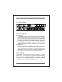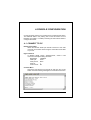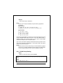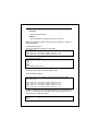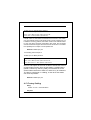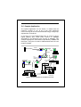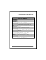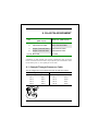
1
NOVASwitch FNSW-1600S FNSW-2400S 10/100Base-TX Fast Ethernet Smart Switch Trademarks Copyright PLANET Technology Corp. 2000. Contents subject to revision without prior notice. PLANET is a registered trademark of PLANET Technology Corp. All other trademarks belong to their respective owners. FCC Warning This equipment has been tested and found to comply with the limits for a Class A digital device, pursuant to Part 15 of the FCC Rules. These limits are designed to provide reasonable protection against harmful interference when the equipment is operated in a commercial environment. This equipment generates, uses, and can radiate radio frequency energy and, if not installed and used in accordance with the Instruction manual, may cause harmful interference to radio communications. Operation of this equipment in a residential area is likely to cause harmful interference in which case the user will be required to correct the interference at his own expense. Revision PLANET NOVASwitch User's Manual FOR MODELS: FNSW-2400S FNSW-1600S Part No.: EM_FNSWSV1 Before Starting In this User's Manual, "Switch" is used for FNSW1600S/2400S, “NovaSwitch” for PLANET’s 19”-range Ethernet Switch, where “switch” represent the third part switch. The term “port 16/24” or “port 12/20” represent port 16 or 12 of FNSW-1600S and port 24 or 20 of FNSW-2400S. PLANET NOVASwitch series TABLE OF CONTENTS 1. UNPACKING INFORMATION........................................... 5 2. PRODUCT INTRODUCTION ............................................. 7 2.1 KEY FEATURES .................................................................... 7 2.2 FRONT PANEL ...................................................................... 8 2.2.1 Ports Speed.................................................................. 8 2.2.2 Cabling ...................................................................... 8 2.2.3 MDI Switch.................................................................. 9 2.2.4 Status LEDs ................................................................. 9 2.3 THE REAR PANEL ............................................................... 10 2.3.1 Extension Slot............................................................ 10 2.3.2 Power Connector ....................................................... 10 2.3.3 Fan .................................................................... 10 2.3.4 RS-232 Console ......................................................... 11 3. INSTALLATION ................................................................ 13 3.1 RACK-MOUNT INSTALLATION ............................................ 13 3.2 DESKTOP INSTALLATION .................................................... 13 3.3 POWER NOTES: .................................................................. 14 4. CONSOLE CONFIGURATION......................................... 15 4.1 CONNECT TO PC ........................................................... 15 4.2 TRUNK/ VLAN SETTING.................................................... 16 4.2.1 Trunking Group Setting ............................................. 16 4.2.2 VLAN Group Setting .................................................. 17 4.3 PORT STATUS .................................................................... 19 4.4 PORT SETTING ................................................................... 19 4.5 FACTORY SETTING ............................................................. 20 4.6 REDUNDANT LINK SETTING ................................................ 21 4.7 SAVE SETTING ................................................................... 21 5. OPTIMIZING CONFIGURATION ................................... 23 5.1 PRIOR TO INSTALLATION .................................................... 23 FNSW-16/2400S User's Manual 5.2 5.3 5.4 5.5 5.6 HALF- AND FULL-DUPLEX .................................................. 23 FAST ETHERNET ................................................................ 24 AUTO-NEGOTIATION.......................................................... 25 MAC ADDRESS TABLE ...................................................... 25 SAMPLE APPLICATION ........................................................ 26 6. TROUBLESHOOTING...................................................... 27 7. PRODUCT SPECIFICATIONS.......................................... 29 8. RJ-45 PIN ASSIGNMENT.................................................. 30 8.1 STRAIGHT-THROUGH/CROSSOVER CABLE ........................... 30 PLANET NOVASwitch series 1.UNPACKING INFORMATION Thank you for purchasing a PLANET NOVASwitch series Ethernet Switches. Before continuing, please check the contents of the product package. This product package should contain the following items: • • • • • One NOVASwitch Ethernet Switch One Power Cord Two Rack-Mounting Brackets with Attachment Screws This User’s Guide RS-232 Console Cable Please inform your local dealer/supplier immediately if any item is found to be defective, damaged or missing. Retain the original packaging (carton), including the packing materials, and use them to re-pack the product in the unlikely event there is a need to return it to us for repair. . FNSW-16/2400S User's Guide 5 This page intentionally left blank! PLANET NOVASwitch series 2.PRODUCT INTRODUCTION NOVASwitch Ethernet Switches are multi-speed, versatile network devices combining both standard and "Big-Pipe" ports under the same hood. 2.1 Key Features • Compliant with IEEE802.3 and 802.3u standards for 10Base-T / 100Base-TX/FX. • 16-port/24-port Fast Ethernet Switch, pure 10/100BaseTX • Wire-speed "Store-and-Forward" filtering/forwarding eliminates bad data packets with minimal delay • 100Base-TX ports automatically sense and set optimal line speed from 10/20, 100/200Mbps, All 100Base-TX port support MII Auto-Negotiation function • Optional Fiber-optic module for 100Base-FX, shared with port16/24. DIP switch for Half/Full-Duplex selection • Shared buffer memory and up to 2K-entry MAC source address table make for fast handling of data packets • Flow control to eliminate packets loss • Internal, full-range power supply suitable for worldwide use • Console port for switch basic management • Either VLAN or Turnk port support managed via console • Up to four port-based VLAN support • Up to four trunk support for up to 800Mbps bandwidth • One Redundant link support FNSW-16/2400S User’s Guide 7 2.2 Front Panel FNSW-1600S Figure 1: Front View of the FNSW-16/2400S 2.2.1 Ports Speed n 100Base-TX All 100Base-TX ports come with auto-negotiation capability. They automatically support 100Base-TX and 10Base-T networks. Users only need to plug a working network device into one of the 100Base-TX ports, then turn on the hub. The port will automatically runs in 10Mbps, 20Mbps, 100Mbps or 200Mbps after the negotiation with the connected device. Port speed adjustment is also available through console port. n 100Base-FX The port 16/24 can be a 100Base-FX fiber-optic port as the extension module installed (rear) At the mean time, the RJ45 port of #16/24 will being disabled. The Half-/Full-Duplex is selectable by the DIP-switch on the module. Please refer to the installation guide of the extension module for more. 2.2.2 Cabling NOVASwitch 100Base-TX ports use RJ-45 sockets -- similar to phone jacks -- for connection of unshielded twisted-pair cable (UTP). The IEEE 802.3u Fast Ethernet standard requires Category 5 UTP for 100Mbps 100Base-TX. 10Base-T networks can use Cat.3, 4, or 5 UTP (see table A below) 8 PLANET NOVASwitch series Port Type Cable Type Connector 10Base-T Cat 3, 4, 5 RJ-45 100Base-TX Cat.5 UTP only RJ-45 100Base-FX* 62.5/125µm multi-mode fiber ST / SC Table A: Supported port list 23 24 19 20 2.2.3 MDI Switch Reset Each numbered port of the Switch are MDI-X port, you can direct use straight cable for the connection to your end nodes. However, port 12/20 is with one push button. To push the button to convert the port to MDI-II port for direct hub cascade. Please also refer to Section “RJ-45 Pin Assignment” for more. 2.2.4 Status LEDs One green LED to show power On/Off is on the front panel, and one “Module Installed” LED indicator to indicate the rear open slot is installed with a fiber-optic module. Also, each port has three status LED indicators, as shown below. LABEL UPPER ROW STATUS / COLOR Steady Amber Blink Amber M IDDLE Steady Green ROW Blink Green M EANING DESCRIPTION FDX Lit to indicate Full-Duplex mode detected on that port COL Blinks if a collision is detected when the port is in Half-Duplex mode. Lit to indicate that a valid physical UTP/STP connection is detected Blink to indicate the port is receiving data packets Link Activity FNSW-16/2400S User’s Guide 9 LOWER Steady Green ROW OFF 100M 10M Lit to indicate that a valid physical UTP/STP connection exists on that port runs in 100Mbps Remains off and Link ON to indicate the port runs in 10Mbps Table B: FNSW-2400S Port-LED Functions 2.3 The Rear Panel Figure 2: Rear View of the Switch 2.3.1 Extension Slot The Switch port 16/24 can be a 100Base-FX switching port as the extension module installed. As the module installed, the port 16/24 on the front panel will be disabled. Please refer to the Installation Guide of the module for the detailed installation and settings. NOTE: While powering on, The Switch detects the DIPswitch status of the module, then shown on the front panel LED indicators 2.3.2 Power Connector The Power Connector is designed to use with the power cord included in the product package. Attach the female end of the cord to the power connector and the male end of the cord to a grounded power outlet. The accepted power range is from 100VAC to 240VAC, 50/60Hz. 2.3.3 Fan All computing and communications devices work best when not overheated. Please keep the fan area clear so that the cooling function is not impaired. 10 PLANET NOVASwitch series 2.3.4 RS-232 Console The RS-232 console helps to manage the Switch. Please use the cable with the package. Attach one end to the switch and the other to your PC’s COM1 or COM2. Then startup your console program like Windows Hyper Terminal, or ProCOMM with parameter: 19200, n, 8, 1. Please refer to Chapter 4, Console management for more. FNSW-16/2400S User’s Guide 11 This page intentionally left blank! 12 PLANET NOVASwitch series 3. INSTALLATION The Switch do NOT require software configuration. Users can immediately use any of the features of this product simply by attaching the cables and turning on the power. However, the Console port will helps to have more setting to your Switch. To get the best use of the Switch, many things need to be considered first. See Chapter 5 for details. 3.1 Rack-Mount Installation Most users prefer to attach the power cord to the hub before installation in a network rack. Do not plug the other end of the cord into a power outlet until after the hub is installed. For mounting the Switch in a network rack, first attach the rack-mount brackets to the side of the hub with screws. (Both brackets and screws are included in the product package.) Slide the hub into the rack and align the holes in the bracket with the corresponding holes in the network rack. Attach the bracket to the rack with the enclosed screws. 3.2 Desktop Installation To locate the Switch on a desktop, first attach the four rubber feet to the bottom of the hub, one in each corner. Place the hub on a clean, flat desk or table-top close to a power outlet. Make sure there is no hindrance behind the fan of the hub Plug in all network connections, then turn the switch on via plug in the power cord. FNSW-16/2400S User’s Guide 13 3.3 Power notes: 1. The device is a power-required device, it means, it will not work till it is powered. If your networks should active all the time, please consider use an UPS (Uninterrupted Power Supply) for your device. It will prevent you from network data loss or network downtime. 2. In some area, installing a surge suppression device may also help to protect your hub from being damaged by unregulated surge or current to the Switch or the power adapter. 14 PLANET NOVASwitch series 4.CONSOLE CONFIGURATION On the rear panel, there is one console port for configuring the switch. The attached cable in the packing box is used to connect to PC’s RS232C port (COM1, or COM2). Following the instructions below to configure the switch. 4.1 CONNECT TO PC RS-232 serial cable Attach the RS-232 cable 9-pin female connector to the male connector on the demo board. Plug the other side of this cable to your PC. Hyper Terminal In Window 95/98, launch “HyperTerminal”, create a new connection and adjust setting as below: Baud Rate: 19200bps Data byte: 8 bits Parity check: None Stop bit: 1 Flow Control: No Console Menu Launch the new terminal you just set up, and then, turn on the Switch. See the following messages for successful connection. FNSW-16/2400S User’s Guide 15 There are six options available for the console setup: (1) Trunk / VLAN Setting (2) Port Status (3) Port Setting (4) Factory Setting (5) Redundant Link (6) Save Setting To enter any of the sub-menu, simply follow the instruction and type the number on the command line, and press ENTER. 4.2 Trunk/ VLAN Setting Entry: Select “1” from <Console Menu> (1) Trunking (2) VLAN Setting (3) Exit >> Purpose: Set up the TRUNKING or VLAN Group Be noted: the Switch support either TRUNKING or VLAN. As soon as one is enabled, it also means the other is turned off at the mean time. Default: No Trunking or VLAN Group in the device . 4.2.1 Trunking Group Setting Entry: Select “1” from Sub Menu, press “ENTER” 4-port Trunk on Port 1/2/3/4 2-Port Trunk on Port 1/2 SWITCH in 1-VLAN mode Trunk (1) Disable (2)2-Port (3)4-Port (4)Cancel Setting>> Purpose: Assign Trunk group setting option. 16 PLANET NOVASwitch series Default: No Trunk Group in the device. Note: As soon as trunk port enabled, the ports will be grouped as followings: 2-port Trunk: 1st group: 1, 3, 5, 7, 9, 11, 13, 15, 17, 21, 23 2nd group: 2, 4, 6, 8, 10, 12, 14, 16, 18, 19, 20, 22, 24 4-port Trunk: 1st: 1, 5, 9, 13, 17, 21 2nd: 2, 6, 10, 14, 18, 22 3rd: 3, 7, 11, 15, 19, 23 4th: 4, 8, 12, 16, 20, 24 Once trunk-port enabled, your are free to connect the Switch to any 3rd party’s standard switch with two links or four links without fears of network looping. The trunks will two or four times the bandwidth between the Switch to the connected switch. After trunk-port enabled, please make the links directly and be sure to make the connection successfully or the group users may fail to access the network resource. Note: Please make sure the switch that your Smart Switch is going to connect to is “Trunking” disabled. That is, either the Smart Switch or any 3rd party switch can turn on the “trunking” at a time. 4.2.2 VLAN Group Setting Entry: Select “2” from sub menu, press “ENTER” PORT 01 02 03 04 05 06 07 08 09 10 11 12 13 14 15 16 17 18 19 20 21 22 23 24 VLAN1 X X X X X X X X X X X X X X X X X X X X X X X X VLAN2 VLAN3 VLAN4 (1)Set VLAN(2)Save/Exit(3)Exit>> FNSW-16/2400S User’s Guide 17 Purpose: Set up the VLAN Group Default: No VLAN Group in the device (all ports in VLAN1) Note: Use Toggle to select VLAN group and “SAVE” to make the setting take effect. VLAN setting example 1, Follow the selection to add port 1 to VLAN2. Enter Port# >> 1 Toggle Group(1~4) to add/remove (5)Update VLAN setting >>2 Toggle Group(1~4) to add/remove (5)Update VLAN setting >>5 The restult is as below: PORT 01 02 03 04 05 06 07 08 09 10 11 12 13 14 15 16 17 18 19 20 21 22 23 24 VLAN1 X X X X X X X X X X X X X X X X X X X X X X X X VLAN2 x VLAN3 VLAN4 (1)Set VLAN(2)Save/Exit(3)Exit>> Follow the steps again to add the VLAN groups. VLAN Setting Example 2 Add port 5 to the four VLANs to maks it server for those VLANs. (1)Set VLAN(2)Save/Exit(3)Exit>> 1 Enter Port# >> 5 Toggle Toggle Toggle Toggle Group(1~4) Group(1~4) Group(1~4) Group(1~4) to to to to add/remove add/remove add/remove add/remove (5)Update (5)Update (5)Update (5)Update VLAN VLAN VLAN VLAN setting setting setting setting >>2 >>3 >>4 >>5 With the setting below, the Switch will separate port 1 to port 4 into 4 VLANs, i.e. those ports can not reach each other. However, they can still access port 5 without problem. PORT VLAN1 VLAN2 18 01 02 03 04 05 06 07 08 09 10 11 12 13 14 15 16 17 18 19 20 21 22 23 24 X X X X X X X X X X X X X X X X X X X X X X X PLANET NOVASwitch series VLAN3 VLAN4 X X X X 4.3 Port Status Entry: Select “2” from < Console Manu> PORT AutoN BackP Pause 01 02 03 04 05 06 07 08 09 10 11 12 13 14 15 16 17 18 19 20 21 22 23 24 X X X X X X X X X X X X X X X X X X X X X X X X X X X X X X X X X X X X X X X X X X X X X X X X X X X X X X X X X X X X X X X X X X X X X X SWITCH in 1-VLAN mode Any key to quit!! Purpose: Display the Port Status group AutoN for “Auto-Negotiaion”, BackP for “Back Pressure”, half-duplex flow control. Pause for “Pause frame” stands for full-duplex flow control. 4.4 Port Setting Entry: Select “3” port setting, press “ENTER” Enter Port Number Purpose: Set up the port setting group Port Setting chart example 1 Set port 1 to works in 100Mbps Full-Duplex mode Enetr Port Number ((qq) to quit)>> 1 Select (1)Port Mode (2)Pause (3)Back Pressure>>1 Select (1)Auto_Nego (2)100FDX (3)100HDX (4)10FDX (5)10HDX>>2 Port Setting chart example 2 FNSW-16/2400S User’s Guide 19 Enable port 2’s PAUSE frame support Enetr Port Number ((qq) to quit)>> 2 Select (1)Port Mode (2)Pause (3)Back Pressure>>2 Select Pause in FDX (1)Enable (2)Disable>>1 PAUSE frame is used while the devices that connect to the Switch runs in Full-duple mode. In full-duplex mode, once the Switch can not handle the incoming packets, the Switch send out the PAUSE frame to warn the device hold the transmission. Be noted, the connected devices should also support the function at the same time or to enable the capability will not helps in avoid packet loss. Default: Enabled per port Port Setting chart example 3 Enable port 3’s Back-pressure. Enetr Port Number ((qq) to quit)>> 3 Select (1)Port Mode (2)Pause (3)Back Pressure>>3 Select Back Pressure in HDX (1)Enable (2)Disable>>1 When a half-duplex device was not able to handle the amount of data it was receiving from an end station, it collided with it (faked a collision by sourcing JAM). Thus all devices on the shared LAN would have to back-off, and then try to retransmit. The device could keep on colliding, so the other end station won’t loss its packets. Default: Enabled per port 4.5 Factory Setting Entry: Select “4” from < Console Manu> Purpose: 20 PLANET NOVASwitch series Set up the Factory default value, the system will be Auto Reboot 4.6 Redundant Link Setting Entry: Select “5” from < Console Manu> Redundant Link on Port-20/Port-19(19 is Backup link) (1)Enable (2)Disable >>1 Purpose: Set up Redundant Link. So the backup line enabled once the primary line is absent. 4.7 Save Setting Entry: Select “6” from < Console Manu> Purpose: Set up the Save Setting, save the setting to EEPROM. FNSW-16/2400S User’s Guide 21 This page intentionally left blank! 22 PLANET NOVASwitch series 5.OPTIMIZING CONFIGURATION 5.1 Prior to Installation Before installing the Switch and connecting network devices, it is important to plan the new network layout. Consider: • Dedicated Bandwidth: File servers and other high-traffic • • • • hardware can improve if they have their own direct connection with dedicated 10 or 100Mbps bandwidth. Full-Duplex: Determine which devices would benefit from a Full Duplex connection and check that they support it. Fast Ethernet: 100Base-TX and 100Base-FX have different rules for cable and distance. Make sure these are followed. Auto-Negotiation: Devices with different speeds may be easily swapped when the other end of the cable is fixed to a port with auto-negotiation. Crossover Uplink: Another hub can be attached to Switch using UTP Crossover function. 5.2 Half- and Full-Duplex The Switch support both Half- and Full-Duplex modes for 10Base-T, 100Base-TX, and 100Base-FX. Half-Duplex mode is the traditional data transfer mode: one station sends data while other devices wait for the first to finish. Full-Duplex is the simultaneous transmission and receiving of data. It is only possible between two devices with a dedicated link (e.g., switch-to-switch, switch-to-PC). Both of the devices must be capable of, and set to, Full-Duplex The 100Base-FX port set Half- or Full-Duplex mode through module's DIP-switch. 100Base-TX ports use auto-negotiation to detect and set the line's operating mode. FNSW-16/2400S User’s Guide 23 5.3 Fast Ethernet 100Base-TX and 100Base-FX are called "Fast Ethernet." This is because they use the Ethernet CSMA/CD access rules and data packet structure, but data travels ten times faster (100Mbps) than traditional 10Mbps Ethernet. Below is a list of the cable types and connectors that supported by Switch for 10Base-T, 100Base-TX, and 100Base-FX networks. PORT TYPE 100BASE-TX 10BASE-T CABLES TYPE Cat. 5 UTP only Cat.3, 4, 5 UTP CONNECTOR RJ-45 RJ-45 Table C: Cables & Connectors Supported by FNSW-2400S In many cases, 10Base-T LANs can quickly and easily upgrade to 100Base-TX networks. Also, 100Base-FX will become more popular due to its longer range. Table lists the maximum Fast Ethernet connection distances. M AX. LINK DISTANCE DTE-DTE¹ 1 Class-I Repeater³ 1 Class-II Repeater 2 Class-II Repeaters COPPER 100m 200m 200m 205m COPPER+FIBER² n/a 261m 309m 216m FIBER 412m/2,000m4 272m 318m 228m NOTES: 1) "DTE" is an end-station such as a PC or switch port 2) Copper+Fiber assumes the max. Copper length is used 3) "Repeater" is a standard hub, NOT a Switch. 4) Half-/Full-Duplex. Fiber's distance depends on mode. Table D: 100Base-TX/FX Topology Rules 24 PLANET NOVASwitch series 5.4 Auto-Negotiation The 100Base-TX ports on the Switch have built-in "AutoNegotiation". This technology automatically sets the best possible bandwidth when a connection is established with another network device (usually at Power On or Reset). This is done by detect the mode and speed at the second device is capable of. The 100Base-TX devices can connect with the 100Base-TX port in either Half- or Full-Duplex mode. If attached device is: 100Mbps, no auto-negotiation 100Mbps, with auto-negotiation 10Mbps, no auto-negotiation 10Mbps, with auto-negotiation 100Base-TX port will set to: 100Mbps (100Base-TX, Half-Duplex) 200Mbps (100Base-TX, Full-Duplex) 10Mbps (10Base-T, Half-Duplex) 20Mbps (10Base-T, Full-Duplex) 5.5 MAC Address Table This 6-byte ID is called the MAC (Media Access Control) Address. Every Ethernet data packet includes both source and destination addresses. The Switch can automatically learn and store up to 2K MAC addresses. The MAC address table is volatile: it disappears when the switch is powered off or reset. Note: When the network needs reconfiguration, we recommend turning off the power first. After all nodes have been moved, power on the switch to rebuild the internal MAC address table. FNSW-16/2400S User’s Guide 25 5.6 Sample Application The optimal application for the Switch, no matter with the extension module or not, is as a "big pipe" backbone interconnecting file servers with bandwidth-hungry workgroups, departments, and offices. In the figure, the first FNSW-2400S links to another switch‘s Uplink (MDI-II) port, some ports connect to 100Mbps Workstations, and attached to file servers at 200Mbps. This example highlight the extra distance provided by 100Base-FX fiber-optic, using the Port #24 of FNSW-2400S with the rear module installed. 200Mbps Server Farm FNSW-2400S 400Mbps 2Km 100Base-FX 100Mbps full duplex FNSW-1600 20Mbps 10Mbps FNSW-2400S FSD-1020 - 200Mbps EH-1602R 10Mbps Server Farm 20Mbps EH-3200 100Mbps 10Mbps DH-1600 Ethernet/Fast Ethernet Hubs 10/100Mbps Workgroup 10/20Mbps Workgroups Figure 3: Sample Application for the Switch with Turnk 26 PLANET NOVASwitch series 6.TROUBLESHOOTING SYMPTOM CHECKPOINT SYMPTOM CHECKPOINT SYMPTOM CHECKPOINT Link LED does not lit after cable is connected to the port. 4 Verify that the other end of the cable is connected to a device that is powered on and on-line. 4 For UTP cable connection to another hub, verify that only one end of the cable is connected to a “MDI-II” Uplink port. 100Base-TX port Link LED is lit, Collision LED is blinking, but traffic is irregular. 4 Check that the attached device is not set to dedicated full-duplex. (Some devices use a physical or software switch to change duplex modes. Auto-negotiation may not recognize this type of full-duplex setting. After setting the DIP-switch of the 100Base-FX module, the attached device doesn’t communicate normally with the port. 4 The attached network device MUST be set to operate in the same duplex mode. ALWAYS CHECK THAT THE CABLE, LINK DISTANCES, AND OVERALL NETWORK DIAMETER ARE WITHIN SPEC. FOR THE NETWORK TYPE. FNSW-16/2400S User’s Guide 27 This page intentionally left blank! 28 PLANET NOVASwitch series 7.PRODUCT SPECIFICATIONS PRODUCT FNSW-1600S / FNSW-2400S NETWORK PORTS 16/24 10/100Base-TX RJ-45 (MDI-X) BUFFER MEMORY 4Mb EXTENSION SLOT 1 open slot (shared with port 16/24 for optional module) MEDIA SUPPORT 100Base-TX Cat. 5 UTP, RJ-45 10Base-T Cat. 3, 4, 5 UTP RJ-45 100Base-TX, 200/100/20/10Mbps, Auto-Negotiation BANDWIDTH FILTER/ FORWARD RATE MAC ADDRESSES SWITCHES 148,800 packets/second per port @ 100Mbps, max. 14,880 packets/second per port @ 10Mbps, max. Up to 2K 6-Byte full MAC address entries max. Self-learning 1 for MDI-X / MDI-II selection for port 12/20 LEDs 1 for Power On/Off, Module Installed 3 per port for 100Mbps, Full-Duplex/ Collision, Act/Link, POWER SUPPLY Auto-switching. Input voltage: 100~240 VAC, 50 ~ 60Hz ENVIRONMENT Operating Temp: 0 ~ 50°C (32 ~ 122°F) Storage Temp: -30 ~ 70°C (-22 ~ 158°F) Humidity 0 ~ 90% non-condensing DIMENSIONS 430 x 180 x 44 mm (16.9 x 7.1 x 1.73 in.) EMISSION FCC Class A, CE SAFETY UL, TUV/GS (EN60950) Table E: Product Specifications FNSW-16/2400S User’s Guide 29 8. RJ-45 PIN ASSIGNMENT 1 Numbered Ports (MDI-X port) Input Receive Data + 2 Input Receive Data - 3 Output Transmit Data+ Input Receive Data + 6 Output Transmit Data- Pin 4,5,7,8 Not used Uplink Port (MDI-II port) Output Transmit Data+ Output Transmit Data- Input Receive Data Not used Schematics for both straight and crossover twisted-pair cable are shown below. (Note that crossover cable is only required if you cascade hubs via the RJ-45 station ports; i.e. the Uplink port is not used.) 8.1 Straight-Through/Crossover Cable The pin assignment of the cables both ends should be as below: Straight-through 6 Crossover Hub (MDI-X) Pin 1 Adapter(MDI-II) Pin 1 Hub (MDI-X) Pin 1 Hub (MDI-X) Pin 3 Pin 2 Pin 3 Pin 6 Pin 2 Pin 3 Pin 6 Pin 2 Pin 3 Pin 6 Pin 6 Pin 1 Pin 2 32 1 6 6 30 32 1 3 21 PLANET NOVASwitch series EMFNSWSv1 ISO9002