1
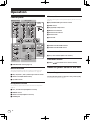
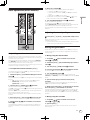
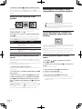
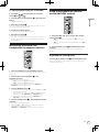
DJ MIXER
DJM-250-K
DJM-250-W
http://www.prodjnet.com/support/
The Pioneer website shown above offers FAQs, information on software and various other types of information
and services to allow you to use your product in greater comfort.
Operating Instructions
Thank you for buying this Pioneer product. Please read through these operating instructions so you will know how to operate your model properly. After
you have finished reading the instructions, put them away in a safe place for future reference.
In some countries or regions, the shape of the power plug and power outlet may sometimes differ from that shown in the explanatory drawings.
However the method of connecting and operating the unit is the same.
1)
2)
3)
4)
5)
6)
7)
Read these instructions.
Keep these instructions.
Heed all warnings.
Follow all instructions.
Do not use this apparatus near water.
Clean only with dry cloth.
Do not block any ventilation openings. Install in
accordance with the manufacturer’s
instructions.
8) Do not install near any heat sources such as
radiators, heat registers, stoves, or other
apparatus (including amplifiers) that produce
heat.
9) Do not defeat the safety purpose of the polarized
or grounding-type plug. A polarized plug has two
blades with one wider than the other. A
grounding type plug has two blades and a third
grounding prong. The wide blade or the third
prong are provided for your safety. If the provided
plug does not fit into your outlet, consult an
electrician for replacement of the obsolete outlet.
10) Protect the power cord from being walked on or
pinched particularly at plugs, convenience
receptacles, and the point where they exit from
the apparatus.
11) Only use attachments/accessories specified by
the manufacturer.
12) Use only with the cart, stand, tripod, bracket, or
table specified by the manufacturer, or sold with
the apparatus. When a cart is used, use caution
when moving the cart/apparatus combination to
avoid injury from tip-over.
13) Unplug this apparatus during lightning storms
or when unused for long periods of time.
14) Refer all servicing to qualified service personnel.
Servicing is required when the apparatus has
been damaged in any way, such as power-supply
cord or plug is damaged, liquid has been spilled
or objects have fallen into the apparatus, the
apparatus has been exposed to rain or moisture,
does not operate normally, or has been dropped.
D3-7-13-69_En
NOTE:
This equipment has been tested and found to comply with the limits for a Class B digital device, pursuant to Part 15
of the FCC Rules. These limits are designed to provide reasonable protection against harmful interference in a
residential installation. This equipment generates, uses, and can radiate radio frequency energy and, if not installed
and used in accordance with the instructions, may cause harmful interference to radio communications. However,
there is no guarantee that interference will not occur in a particular installation. If this equipment does cause
harmful interference to radio or television reception, which can be determined by turning the equipment off and on,
the user is encouraged to try to correct the interference by one or more of the following measures:
— Reorient or relocate the receiving antenna.
— Increase the separation between the equipment and receiver.
— Connect the equipment into an outlet on a circuit different from that to which the receiver is connected.
— Consult the dealer or an experienced radio/TV technician for help.
D8-10-1-2_A1_En
This Class B digital apparatus complies with Canadian ICES-003.
D8-10-1-3_A1_En
Information to User
Alterations or modifications carried out without appropriate authorization may invalidate the user’s right to operate
the equipment.
D8-10-2_A1_En
IMPORTANT NOTICE
THE MODEL NUMBER AND SERIAL NUMBER OF THIS EQUIPMENT ARE ON THE REAR OR BOTTOM.
RECORD THESE NUMBERS ON PAGE 19 FOR FUTURE REFERENCE.
D36-AP9-1_A1_En_PSV
2
En
WARNING
This equipment is not waterproof. To prevent a fire or
shock hazard, do not place any container filled with
liquid near this equipment (such as a vase or flower
pot) or expose it to dripping, splashing, rain or
moisture.
D3-4-2-1-3_A1_En
WARNING: Handling the cord on this product or
cords associated with accessories sold with the
product may expose you to chemicals listed on
proposition 65 known to the State of California and
other governmental entities to cause cancer and
birth defect or other reproductive harm.
D36-P5_B1_En
WARNING
Before plugging in for the first time, read the following
section carefully.
The voltage of the available power supply differs
according to country or region. Be sure that the
power supply voltage of the area where this unit
will be used meets the required voltage (e.g., 230 V
or 120 V) written on the side panel.
This product is for general household purposes. Any
failure due to use for other than household purposes
(such as long-term use for business purposes in a
restaurant or use in a car or ship) and which requires
repair will be charged for even during the warranty
period.
K041_A1_En
D3-4-2-1-4*_A1_En
POWER-CORD CAUTION
WARNING
Operating environment temperature and humidity:
+5 °C to +35 °C (+41 °F to +95 °F); less than 85 %RH
(cooling vents not blocked)
Do not install this unit in a poorly ventilated area, or in
locations exposed to high humidity or direct sunlight (or
strong artificial light)
Handle the power cord by the plug. Do not pull out the
plug by tugging the cord and never touch the power
cord when your hands are wet as this could cause a
short circuit or electric shock. Do not place the unit, a
piece of furniture, etc., on the power cord, or pinch the
cord. Never make a knot in the cord or tie it with other
cords. The power cords should be routed such that they
are not likely to be stepped on. A damaged power cord
can cause a fire or give you an electrical shock. Check
the power cord once in a while. When you find it
damaged, ask your nearest PIONEER authorized
service center or your dealer for a replacement.
D3-4-2-1-7c*_A1_En
S002*_A1_En
To prevent a fire hazard, do not place any naked flame
sources (such as a lighted candle) on the equipment.
D3-4-2-1-7a_A1_En
Operating Environment
If the AC plug of this unit does not match the AC
outlet you want to use, the plug must be removed
and appropriate one fitted. Replacement and
mounting of an AC plug on the power supply cord of
this unit should be performed only by qualified
service personnel. If connected to an AC outlet, the
cut-off plug can cause severe electrical shock. Make
sure it is properly disposed of after removal.
The equipment should be disconnected by removing
the mains plug from the wall socket when left unused
for a long period of time (for example, when on
vacation).
D3-4-2-2-1a_A1_En
CAUTION
The ON/OFF switch on this unit will not completely
shut off all power from the AC outlet. Since the power
cord serves as the main disconnect device for the
unit, you will need to unplug it from the AC outlet to
shut down all power. Therefore, make sure the unit
has been installed so that the power cord can be
easily unplugged from the AC outlet in case of an
accident. To avoid fire hazard, the power cord should
also be unplugged from the AC outlet when left
unused for a long period of time (for example, when
on vacation).
D3-4-2-2-2a*_A1_En
The Safety of Your Ears is in Your Hands
Get the most out of your equipment by playing it at a
safe level – a level that lets the sound come through
clearly without annoying blaring or distortion and, most
importantly, without affecting your sensitive hearing.
Sound can be deceiving. Over time, your hearing
“comfort level” adapts to higher volumes of sound, so
what sounds “normal” can actually be loud and
harmful to your hearing. Guard against this by setting
your equipment at a safe level BEFORE your hearing
adapts.
ESTABLISH A SAFE LEVEL:
• Set your volume control at a low setting.
• Slowly increase the sound until you can hear it
comfortably and clearly, without distortion.
• Once you have established a comfortable sound
level, set the dial and leave it there.
BE SURE TO OBSERVE THE FOLLOWING
GUIDELINES:
• Do not turn up the volume so high that you can’t
hear what’s around you.
• Use caution or temporarily discontinue use in
potentially hazardous situations.
• Do not use headphones while operating a motorized
vehicle; the use of headphones may create a traffic
hazard and is illegal in many areas.
S001a_A1_En
En
3
Contents
How to read this manual
The names of displays, menus, and buttons in this manual are enclosed
in brackets. (e.g. [MASTER] channel, [ON/OFF], [File] menu)
Before start
Features........................................................................................................ 5
System setup example................................................................................ 5
What’s in the box......................................................................................... 5
Connections
Names of Parts............................................................................................ 6
Connecting the input/output terminals..................................................... 7
About the AC adapter.................................................................................. 8
Operation
Control panel.............................................................................................. 10
About the power switch of this unit......................................................... 10
Basic operations (mixer section)............................................................. 11
Using the filter function (filter section).................................................... 12
Selecting the crossfader’s curve characteristics
(crossfader section)................................................................................... 12
Starting playback of a Pioneer DJ player using the fader
(fader start section)................................................................................... 12
Monitoring the sound over headphones (headphones section)........... 13
Using a microphone or external device (MIC/AUX section).................. 13
Additional information
Troubleshooting......................................................................................... 14
Block Diagram........................................................................................... 14
About trademarks and registered trademarks....................................... 15
Specifications............................................................................................ 15
4
En
Before start
Before start
Features
This unit is a DJ mixer that carries over the technology of the Pioneer DJM series, the world standard in club sound. It is a standard type unit equipped
with the basic functions required for mixing, enabling full-fledged DJ play easily.
SOUND COLOR FILTER
MIC/AUX INPUT
Each channel is equipped with a SOUND COLOR FILTER function by
which filter effects can be achieved simply by turning a large control.
This lets you arrange and mix tracks intuitively for DJ performances.
This unit is equipped with three sets of AUX inputs for input of audio
signals from external devices (computers, portable audio sets, TVs,
synthesizers, etc.), as well as a microphone input. It can be used not only
for DJ performances, but also as a pre-amp to appreciate music.
3-BAND EQUALIZER
XLR OUTPUT
This unit is equipped with a 3-band equalizer allowing the volume of
the high, medium and low frequency ranges to be adjusted separately.
Not only can the tone be adjusted to your tastes, the sound for a certain
range can be turned completely off by turning the control all the way
counterclockwise (isolator function).
This unit is equipped with XLR balanced outputs featuring little loss of
audio signal quality, enabling DJ performances with high sound quality.
Also, it can be connected to powered speakers or other devices supporting XLR inputs without any changes to the terminals.
System setup example
A DJ system like the one shown on the diagram below can be achieved by combining this unit with a DJ player and peripheral equipment.
For audio input
For audio output
INPUT
INPUT
1
1
2
EQ
2
3
EQ
POWER 4
Synthesizers,
computers,
portable audio devices,
microphones, etc.
Powered speakers,
components,
amplifiers, etc.
S-DJ05, etc.
MIC/AUX
MIC
OFF
TRIM
AUX 1
CD
AUX 2
TIME MODE
BACK
REMAIN
M
S
F
TEMPO
LOCK
AUTO CUE
A.CUE
HI
CH-1
DISC
0
9
HI
MID
BPM
LOCK
PLAYLIST
EQ
12
9
12
LOW
OUT
RELOOP/EXIT
ON
2 CHANNEL DJ MIXER
DJM-250
TIME MODE
BACK
BEAT LOOP
LOW
VINYL MODE
LOOP
LOOP DRIVE
TEMPO RANGE
12
9
12
OVER
OVER
+4
+4
+2
+2
0
0
-6
-6
-12
-12
-18
-18
dB
dB
0
9
S
F
TEMPO
A.CUE
%
16
BPM
SELECT PUSH
INFO
DISPLAY
BROWSE
USB
STOP
CH-2
M
LOCK
AUTO CUE
MASTER LEVEL
MASTER
SELECT PUSH
MP3/AAC
WAV/AIFF
OUT ADJUST
OFF
TRIM
9
HI
LEVEL
BPM
UTILITY
IN/CUE
PHONO
/LINE
9
BROWSE
HOT LOOP
CD
REMAIN
16
SOURCE SELECT
TRACK SEARCH
PHONO
/LINE
AUX 3
%
INFO
DISPLAY
USB
STOP
3
POWER 4
DISC
UTILITY
MID
SOURCE SELECT
EQ
BPM
LOCK
PLAYLIST
MP3/AAC
WAV/AIFF
9
LOW
TRACK SEARCH
IN/CUE
OUT
HOT LOOP
OUT ADJUST
RELOOP/EXIT
BEAT LOOP
VINYL MODE
LOOP
LEVEL
9
SEARCH
LOOP DRIVE
TEMPO RANGE
SEARCH
MASTER TEMPO
MASTER TEMPO
SOUND COLOR FILTER
TEMPO
TEMPO
LPF
HPF
LPF
HPF
HEADPHONES
FADER START
CH-1
CH-1
CH-2
CH-2
MIXING
0
CUE
0
CUE
MASTER
CROSS FADER
LEVEL
CUE
THRU
CH-1
PLAY/PAUSE
CH-2
PLAY/PAUSE
0
REV
FWD
REV
MULTI PLAYER
FWD
MULTI PLAYER
PHONES
CDJ-350, etc.
DJM-250
CDJ-350, etc.
For checking the
audio input/output
Headphones
HDJ-500, etc.
What’s in the box
! AC adapter
! Power plug
! Operating instructions (this document)
En
5
Connections
Be sure to turn off the power and unplug the AC adapter from the power outlet before making or changing connections between devices.
Wait until all connections between devices have been completed before connecting the AC adapter.
Only use the AC adapter included with this unit.
Refer to the operating instructions for the component to be connected.
Names of Parts
Rear panel, front panel
1
2
3 4
5 6
CH-2
ON
PHONO / LINE
OFF
SIGNAL
GND
CD
L
LINE
7 3 4
CONTROL
PHONO
LINE
8
CH-1
PHONO / LINE
3
2
L
MIC
CONTROL
PHONO
1
R
L
9
AUX
CD
L
R
R
DC IN
5 6
R
R
L
1GND
3 COLD
2 HOT
MASTER 2
c
b
MASTER 1
a
1ON/OFF switch (page 10)
Turns this unit’s power on and off.
2DC IN terminal
Connect to a power outlet using the included AC adapter (with the
power plug mounted).
Wait until connection of all equipment is completed before connecting the AC adapter.
Only use the included AC adapter.
3PHONO/LINE selector switch (page 7)
Switches the function of the [PHONO/LINE] terminals.
d
aMASTER 1 terminals (page 7)
Connect powered speakers, etc., here.
! Compatible with XLR connector type balanced outputs.
bMASTER 2 terminals (page 7)
Connect powered speakers, etc., here.
! Compatible with RCA pin-jack type unbalanced outputs.
cCord hook
Hook the AC adapters’ power cord here.
dKensington security slot
!
CAUTION
When switching the [PHONO/LINE] selector switch, set
[MASTER LEVEL] to [-∞]. Note that noise may be generated and
sound output at a high volume.
4PHONO/LINE terminals (page 7)
Connect a phono level output device (analog player (for MM cartridges), etc.) or a line level output device (DJ player, etc.) here.
Switch the terminals’ function according to the connected device
using the [PHONO/LINE] selector switch on this unit’s rear panel.
5CD terminals (page 7)
Connect to a DJ player or other line level device.
6CONTROL terminal (page 7)
Connect using a control cord (included with Pioneer DJ players).
7SIGNAL GND terminal (page 7)
Connect an analog player’s ground wire here. This helps reduce
noise when the analog player is connected.
8AUX terminals (page 7)
Connect to the output terminals of external devices (computers,
portable audio sets, TVs, synthesizers, etc.).
9MIC terminal (page 7)
Connect to a microphone.
6
En
e
ePHONES jack (page 7)
Connect headphones here.
Connecting the input/output terminals
Rear panel, front panel
Audio input
section
Connections
! When creating a DVS (Digital Vinyl System) combining a computer, audio interface, etc., be careful in connecting the audio interface to this unit’s
input terminals and in the settings of the input selector switches.
Also refer to the operating instructions of the DJ software and audio interface.
Example:
CDJ-350
Audio cable
R
DJ player
L
L
R
AUDIO
OUT
Analog player
Control cord 1
CONTROL
USB
To ground wire
terminals
To audio output
terminals
Ground wire
Audio cable
Microphone
Microphone cable
Rear panel
CH-2
To power outlet
ON
PHONO / LINE
OFF
SIGNAL
GND
CD
L
CH-1
PHONO / LINE
LL
L
LINE
CONTROL
PHONO
R
LINE
R
3
L
R
2
L
CONTROL
R
R
DC IN
CD
R
PHONO
To microphone
AUX
L
L
R
RR
MIC
Portable audio
device
1
L
1GND
Audio cable
3 COLD
2 HOT
AC adapter
(included)
R
L
MASTER 2
To audio output
terminals
MASTER 1
Audio output
section
Computer
Powered speaker, component,
amplifier, etc.
Front panel
INPUT
Headphones
INPUT
1
3
To audio output
terminals
1
2
EQ
POWER 4
Audio cable
2
EQ
3
POWER 4
synthesizer
To audio input terminals
Audio cable
Headphones
cord
Audio cable
To audio output
terminals
Audio cable
1 To use the fader start function, connect a control cord (page 12).
The fader start function can only be used when connected to a Pioneer DJ player.
Cord hook
Loosen the cord hook’s screw and pinch the AC adapters’
power cord under the hook.
Cord hook
R
DC IN
R
L
MASTER 2
AC adapter’ s power cord
! Place the cord hook out of reach of children. If a child should
swallow it, contact a physician immediately.
En
7
About the AC adapter
Safety instructions
To ensure your personal safety and to maximize the full operating potential of your unit, read and follow these safety instructions.
Read & Retain Instructions
Read all operating and user information provided with this product.
Cleaning
Use a damp cloth to clean the exterior housing. Avoid using any fluids
including liquid, aerosol or alcohol-based cleaning products.
Water or Moisture
Check that there are no irregularities with the AC adapter or power plug,
then insert the power plug into the specified position of the AC adapter
using the specified procedure until a click is heard. For details, see
Mounting the power plug on page 9.
If there are irregularities with the AC adapter or power plug, ask your
nearest Pioneer authorized service center or your dealer to carry out
repair work.
! Do not place the AC adapter cord around your neck. Doing so could
result in suffocation.
! Do not use this unit with a coin, paper clip or other metal object
stuck between the AC adapter and power plug. Doing so could cause
a short circuit, leading to fire or electric shock.
Avoid operating or locating this product near water or other sources of
fluid.
Accessories
Do not place this product on an unstable cart, stand, or table. The product may fall and be seriously damaged.
Ventilation
Do not block or cover this product in use. This unit should not be placed
in a built-in installation unless properly ventilated.
Environment
Avoid placing this product in a location with exposure to large quantities
of dust, high temperatures, high humidity, or subject to excessive vibrations or shocks.
Power Sources
! When mounting the AC adapter on a wall outlet, make sure there is
no space between the AC adapter and the wall outlet. Faulty contact
or a coin, paper clip or other metal object getting stuck in the space
could cause a short circuit, leading to fire or electric shock.
Coin, paper clip or other metal object
Operate this product only from the recommended power sources. If
you are unsure of the power source, consult an authorized Pioneer
representative.
Power-Cord Protection
When unplugging the unit, pull on the plug – not on the cord. Do not
handle the cord or plug with wet hands; doing so could cause an electric
short or shock. Do not allow anything to pinch or rest on the power cord
and do not place in a walkway.
Power
Turn OFF the system before installing this or any other hardware device.
Overloading
Avoid connecting too many devices to a single wall socket or power
source as this can cause fires or short circuits.
Object & Liquid Entry
Never push inappropriate objects in to the device. Avoid spilling any
liquids in to or on the outside of the drive.
Top
Side
! The power plug could come detached from the AC adapter and
remain in the power outlet if someone trips on the AC adapter’s
power cord or if something hits the AC adapter. If this happens,
remove the power plug remaining in the outlet with dry hands, holding it as shown on the diagram below and without touching metal
parts. Do not use any tools to remove it.
Servicing
Opening or removing the cover exposes you to possible electrical shock
or other danger. Contact a Pioneer authorized service representative for
repairing this product (refer to the enclosed Service & Support Card).
Damage Requiring Service
Unplug the unit and refer servicing to qualified service personnel in the
following situations:
! When the power cord, plug, or chassis is damaged.
! If liquid has been spilled, or objects have fallen into the product.
! If the product has been exposed to rain or water.
! If the product does not operate normally when the operating instructions are followed. Adjust only those controls that are covered by the
operating instructions. Improper adjustment of other controls may
result in damage and can require extensive work by a qualified technician to restore the unit to its normal operation.
! When the product exhibits a distinct change in performance – this
indicates a need for service.
8
En
Do not touch.
Mounting the power plug
Connections
Slide the power plug along the guide rails in the AC
adapter unit as shown on the diagram below, then press
in until a click is heard.
Removing the power plug
While pressing the [PUSH] button on the AC adapter
unit, slide the power plug away from the adapter as
shown on the diagram below to remove it.
Once the power plug is mounted, there is no need to remove it.
Power plug
The power plug shown below is included with this product.
En
9
Operation
Mixer section
Control panel
MIC/AUX section
9
MIC/AUX
MIC
OFF
TRIM
AUX 1
AUX 2
2
AUX 3
LEVEL
Two sets of audio signals can be adjusted separately for basic DJ mixing
(page 11).
Mixer section
CD
a
b
PHONO
/LINE
CD
ON
9CD, PHONO/LINE input selector switch
2 CHANNEL DJ MIXER
c
9
OFF
TRIM
PHONO
/LINE
9
HI
HI
a
b
DJM-250
aTRIM control
MASTER LEVEL
MASTER
3
CH-1
0
9
HI
d
MID
EQ
4
12
9
12
LOW
LOW
12
OVER
+4
+4
+2
+2
0
0
-6
-6
-12
-12
-18
-18
dB
dB
0
9
d
bEQ (HI, MID, LOW) control
cMaster level indicator
MID
EQ
dChannel level indicator
9
LOW
LEVEL
9
12
1
CH-2
OVER
eChannel fader
9
fCrossfader
g
SOUND COLOR FILTER
h
h
LPF
5
Filter section
HPF
LPF
Filter section
HPF
HEADPHONES
FADER START
CH-1
CH-1
CH-2
CH-2
i
MIXING
CUE
Fader start
section
e
6
MASTER
hSOUND COLOR FILTER control
CROSS FADER
LEVEL
THRU
CH-1
7
gSOUND COLOR FILTER indicator
CH-2
f
0
j
Crossfader
section
8
Fader start section
iCH-1, CH-2 buttons (fader start section)
PHONES
Headphones
section
Mixer section
1MASTER LEVEL control (page 11)
MIC/AUX section
This section handles the sound of microphones or external devices
(computers, portable audio sets, TVs, synthesizers, etc.) (page 13).
Crossfader section
jTHRU,
,
(crossfader curve selector switch)
About the power switch of this unit
To turn the power on
2MIC, OFF, AUX 1, AUX 2, AUX 3 input selector switch
3LEVEL control (MIC/AUX section)
4HI, LOW controls
Headphones section
The sound being input to this unit can be checked over headphones
(page 13).
5CH-1, CH-2 buttons (headphones section)
6MIXING control
7LEVEL control (headphones section)
8PHONES jack
10
En
Set the [ON/OFF] switch on this unit’s rear panel to [ON].
This turns this unit’s power on (page 6).
Basic operations (mixer section)
9
TRIM
CD
a
b
PHONO
/LINE
CD
TRIM
PHONO
/LINE
c
9
9
HI
HI
a
b
9
MID
d
EQ
9
LOW
1
CH-2
OVER
OVER
+4
+4
+2
+2
0
0
-6
-6
-12
-12
-18
-18
dB
dB
6 Turn the [MASTER LEVEL] control 1 clockwise.
9
d
MID
EQ
9
LOW
LEVEL
9
Switch the channel whose sound is output from the speakers.
— Left edge: The [CH-1] sound is output.
— Center position: The sound of [CH-1] and [CH-2] is mixed and
output.
— Right edge: The [CH-2] sound is output.
! This operation is not necessary when the [THRU,
,
] (crossfader curve selector) switch is set to [THRU].
2
9
Sound is output from the speakers.
The master level indicator c on the control panel lights.
Adjust [MASTER LEVEL] so that the orange indicator lights at the point
in the track where the volume is loudest (the climax, etc.).
Be careful that the red indicator does not light, or the sound could be
distorted.
Operation
MASTER
CH-1
5 Move the crossfader f.
SOUND COLOR FILTER
LPF
HPF
LPF
HPF
Turn the [CH-1] 1 or [CH-2] 2 EQ (HI, MID, LOW) control
b.
e
CH-1
Adjusting the sound quality
CH-2
f
Refer to Specifications on page 15 for the range of sound that can be
adjusted by each control.
! The sound for that range can be turned completely off by turning the
control all the way counterclockwise (isolator function).
Mixing using the faders
Outputting sound
Check that this unit is properly connected to the DJ player, etc., before
outputting sound. For instructions on connections, see Connecting the
input/output terminals on page 7.
Set the volume of the powered speakers connected to the [MASTER 1]
and [MASTER 2] terminals to a suitable level. Note that sound will be
output at a high volume if the volume is set too high.
For instructions on monitoring the sound, see Monitoring the sound over
headphones (headphones section) on page 13.
To output the sound of channel 1 [CH-1] 1
Prepare the unit in advance so that the sound of [CH-1] 1 is being output from the speakers. For instructions on preparation, see Outputting
sound on page 11.
Mixing using the channel faders
1 Set [THRU, , ] (the crossfader curve selector
switch) j to [THRU].
2 Switch the [CH-2] 2 [CD, PHONO/LINE] input selector
switch 9.
3 Turn the [CH-2] 2 [TRIM] control a clockwise.
4 Press the [CH-2] button 5 in the headphones section.
To output the sound of channel 2 ([CH-2]) 2, perform the procedure
below replacing [CH-1] with [CH-2].
The sound of [CH-2] is monitored from the headphones.
1 Switch the [CH-1] 1 [CD, PHONO/LINE] input selector
switch 9.
Adjust the monitor volume balance of the sound output from the
[MASTER 1] or [MASTER 2] terminals (the [CH-1] sound) and the [CH-2]
sound.
Select the input source for [CH-1] from among the devices connected to
this unit.
—[CD]: Selects the DJ player connected to the [CD] terminals.
—[PHONO/LINE]: Selects the device connected to the
[PHONO/LINE] terminals.
2 Turn the [CH-1] 1 [TRIM] control a clockwise.
Adjusts the audio level input to the [CH-1] terminal.
The [CH-1] channel level indicator d lights when audio signals are being
properly input to [CH-1].
Adjust the [TRIM] control so that the orange indicator lights where the
track’s volume is highest (at the climax, etc.)
Be careful that the red indicator does not light, or the sound could be
distorted.
3 Move the [CH-1] 1 channel fader e away from you.
The level of the sound output from the [CH-1] terminals is adjusted.
4 Switch [THRU,
switch) j.
,
] (the crossfader curve selector
This switches the crossfader’s curve characteristics. For details, see
Selecting the crossfader’s curve characteristics (crossfader section) on
page 12.
5 Turn the [MIXING] control 6.
6 Operate the DJ player connected to the [CH-2]
terminals.
While checking the sound over the headphones, adjust the tempo of
[CH-2] track to match the tempo of [CH-1] track.
7 While moving the [CH-2] 2 channel fader to the back,
move the [CH-1] 1 channel fader to the front.
While checking the sound output from the speakers, operate the channel faders to substitute the sound of [CH-1] with the sound of [CH-2].
Mixing is completed once only the [CH-2] sound is being output from the
speakers.
Mixing using the crossfader
1 Set [THRU, , ] (the crossfader curve selector
switch) j to [ ] or [ ].
2 Operate [CH-2] 2.
Operate as described in steps 2 to 6 under Mixing using the channel
faders on page 11.
En
11
3 Move the crossfader f gradually towards the right.
While checking the sound output from the speakers, operate the crossfader to substitute the sound of [CH-1] with the sound of [CH-2].
Mixing is completed once only the [CH-2] sound is being output from the
speakers.
Selecting the crossfader’s curve
characteristics (crossfader section)
CROSS FADER
THRU
j
Using the filter function (filter
section)
g
SOUND COLOR FILTER
1
2
LPF
HPF
LPF
h
HPF
h
Each channel is equipped with a SOUND COLOR FILTER function by
which filter effects can be achieved simply by turning a large control.
The treble or bass sound can be removed by turning the
[SOUND COLOR FILTER] control h.
Turn the [CH-1] 1 or [CH-2] 2 [SOUND COLOR FILTER]
control h.
The effect is applied to the sound and the indicator’s color changes.
The effect type and indicator color differs according to the direction in
which the [FILTER] control is turned, as shown on the table below.
Direction of
rotation
Description of effect
Indicator
Left
Applies the effect of the
treble sound fading out.
(LPF: low pass filter)
Red (flashing)
Center
—
Orange (lit)
Right
Applies the effect of the bass
sound fading out.
(HPF: high pass filter)
Green (flashing)
Mixing using the SOUND COLOR FILTER
control
Prepare the unit in advance so that the sound of [CH-1] 1 is being output from the speakers. For instructions on preparation, see Outputting
sound on page 11.
For instructions on monitoring the sound, see Monitoring the sound over
headphones (headphones section) on page 13.
1 Operate the crossfader and [CH-2] 2.
Operate as described in steps 2 to 6 under Mixing using the channel
faders on page 11.
Starting playback of a Pioneer DJ
player using the fader (fader start
section)
FADER START
CH-1
CH-2
i
If you connect a Pioneer DJ player using a control cable (supplied with
a DJ player), you can start playback of control other operations of the DJ
player with the fader of this unit.
The fader start function can only be used when connected to a Pioneer
DJ player.
Connect this unit and Pioneer DJ player beforehand. For instructions on
connections, see Connecting the input/output terminals on page 7.
To start playback using the channel
faders
1 Set [THRU, , ] (the crossfader curve selector
switch) j to [THRU].
2 Press the [CH-1] or [CH-2] button i in the fader start
section.
Turn the fader start function on.
3 Move the channel fader e to the very front.
2 Turn the [CH-2] 2 [SOUND COLOR FILTER] control h
fully clockwise.
4 Set the cue on the DJ player.
3 Move the [CH-2] 2 channel fader e away from you.
5 Move the channel fader e away from you.
4 While turning the [CH-1] 1 [SOUND COLOR FILTER]
control h counterclockwise from the center, turn the
[CH-2] 2 [SOUND COLOR FILTER] control h towards the
center.
While checking the sound output from the speakers, operate the
[SOUND COLOR FILTER] controls h and replace the [CH-1] and [CH-2]
sound.
Move the [CH-1] 1 channel fader e towards the front. Mixing is completed once only the sound of [CH-2] is output from the speakers.
12
—[THRU]: Choose this when you do not want to use the crossfader.
—[ ]: Set here for a curve that rises gradually.
—[ ]: Set here for a curve that rises steeply. (When the crossfader
moves away from either the left or right edge, the sound is immediately output from the opposite side.)
En
The DJ player pauses playback at the cue point.
Playback starts on the DJ player.
! If you set the channel fader back to the original position, the player
instantaneously returns to the cue point already set and pauses
playback (back cue).
To start playback using the crossfader
1 Set [THRU, , ] (the crossfader curve selector
switch) j to [ ] or [ ].
Using a microphone or external
device (MIC/AUX section)
MIC/AUX
MIC
Turn the fader start function on.
AUX 1
AUX 2
AUX 3
LEVEL
3
3 Move the crossfader f.
0
HI
Move the crossfader to the opposite edge from the channel for which
you want to use the fader start function.
4
4 Set the cue on the DJ player.
The DJ player pauses playback at the cue point.
5 Move the crossfader f.
Playback starts on the DJ player.
! If you set the crossfader back to the original position, the player
instantaneously returns to the cue point already set and pauses
playback (back cue).
Monitoring the sound over
headphones (headphones section)
HEADPHONES
CH-1
5
OFF
2
Operation
2 Press the [CH-1] or [CH-2] button i in the fader start
section.
12
12
LOW
12
12
1 Switch the [MIC, OFF, AUX 1, AUX 2, AUX 3] input
selector switch 2.
—[MIC]: The microphone connected to the [MIC] terminal is
selected.
—[AUX1–3]: Selects the external device connected to the [AUX1–3]
terminals.
2 Turn the [LEVEL] control 3 in the MIC/AUX section
clockwise.
The sound of the microphone or external device is output from the
speakers.
CH-2
MIXING
6
CUE
Adjusting the sound quality
MASTER
LEVEL
Turn the [HI] or [LOW] control 4 in the MIC/AUX section.
7
0
Refer to Specifications on page 15 for the range of sound that can be
adjusted by each control.
8
PHONES
1 Connect headphones to the [PHONES] terminal.
For instructions on connections, see Connecting the input/output terminals on page 7.
2 Press the [CH-1] or [CH-2] button 5 in the
headphones section.
Select the channel you want to monitor.
—[CH-1]: The sound of [CH-1] is monitored.
—[CH-2]: The sound of [CH-2] is monitored.
! This operation is not necessary to monitor the [MASTER 1] or
[MASTER 2] (master channel) sound.
3 Turn the [MIXING] control 6.
— When turned counterclockwise: The volume of [CH-1] and [CH-2]
becomes relatively louder.
— Center position: The volume of the [CH-1] and [CH-2] sound is
the same level as the [MASTER 1] and [MASTER 2] sound.
— When turned clockwise: The volume of [MASTER 1] and
[MASTER 2] become relatively louder.
4 Turn the [LEVEL] control 7 in the headphones section
clockwise.
Sound is output from the headphones.
! When the [CH-1] or [CH-2] button in the headphones section is
pressed again, monitoring is canceled.
![MASTER 1] and [MASTER 2] monitoring cannot be canceled.
En
13
Additional information
Troubleshooting
! Incorrect operation is often mistaken for trouble or malfunction. If you think that there is something wrong with this component, check the points
below. Sometimes the trouble may lie in another component. Inspect the other components and electrical appliances being used. If the trouble
cannot be rectified after checking the items below, ask your nearest Pioneer authorized service center or your dealer to carry out repair work.
! This unit may not operate properly due to static electricity or other external influences. In this case, proper operation may be restored by turning the
power off, waiting 1 minute, then turning the power back on.
Problem
Check
Remedy
The power is not turned on.
Is the included AC adapter properly connected?
Connect the included AC adapter properly to the power outlet. (page 7)
Properly attach the included AC adapter’s power cord to this unit’s cord hook.
(Page 7)
No sound or small sound.
Is the [ON/OFF] switch for power supply set to
[ON]?
Set the [ON/OFF] switch for power supply to [ON]. (Page 10)
Is the [CD, PHONO/LINE] input selector switch set
to the proper position?
Switch the [CD, PHONO/LINE] input selector switch to the channel’s input
source. (Page 11)
Is the [PHONO/LINE] selector switch on this unit’s
rear panel set to the proper position?
Switch the terminals’ function using the [PHONO/LINE] selector switch on this
unit’s rear panel. (Page 6)
Are the [TRIM], [channel fader], [crossfader]
and [MASTER LEVEL] controls set to the proper
positions?
Set the [TRIM], [channel fader], [crossfader] and [MASTER LEVEL] controls to
the proper positions. (Page 11)
Are the connected powered speakers, etc., properly set?
Properly set the external input selection, volume, etc., on the powered speakers,
etc.
Are the connection cables properly connected?
Connect the connection cables properly. (page 7)
Are the terminals and plugs dirty?
Clean the terminals and plugs before making connections.
Is [MASTER LEVEL] set at the proper position?
Adjust the [MASTER LEVEL] control so that the master level indicator’s orange
indicator lights at the peak level. (Page 11)
Is [TRIM] set at the proper position?
Adjust the [TRIM] control so that the channel level indicator’s orange indicator
lights at the peak level. (Page 11)
Can’t crossfade.
Is the [THRU,
,
] (crossfader curve selector)
switch set to [THRU]?
Set the [THRU,
,
] (crossfader curve selector) switch to a position other
than [THRU]. (Page 11)
Can’t fader start a DJ player.
Is the [CH-1] or [CH-2] button in the fader start
section set to the off position?
Set the [CH-1] or [CH-2] button in the fader start section to the on position. (page
12)
Is the control cord properly connected?
Connect this unit and DJ player with a control cord. (page 7)
Are the audio cables properly connected?
Connect this unit to the audio output terminal of a DJ player with an audio cable.
(page 7)
Have you connected an analog player with a builtin phono equalizer?
If the analog player is equipped with a built-in phono equalizer, connect it to the
[CD] terminals. (page 7)
Distorted sound.
Sound is distorted when an analog
player is connected to this unit’s
[PHONO/LINE] terminals.
Or, lighting of the channel level
indicator does not change even when
the [TRIM] control is turned.
If the analog player with built-in phono equalizer has a PHONO/LINE selector
switch, switch it to PHONO.
Is an audio interface for computers connected
between the analog player and this unit?
If the computer audio interface’s output is line level, connect it to the [CD]
terminals. (page 7)
If the analog player has a PHONO/LINE selector switch, switch it to PHONO.
Block Diagram
CD1
TRIM
LINE1/
PHONO1
3Band
EQ
MASTER LEVEL
METER
FILTER
CH 1
LEVEL METER
HP CH 1
CH 1
FADER
CD2
TRIM
LINE2/
PHONO2
3Band
EQ
OFF
AUX 1
CROSS
FADER
FILTER
CH 2
LEVEL METER
HP CH 2
MIC
LEVEL
CH 2
FADER
AUX 2
HP MASTER
AUX 3
HP CH 1
HP OUT
HP MIX
En
HP VOL
MASTER
VOL
HP MASTER
2Band
EQ
HP CH 2
14
MASTER 1 OUT
MASTER 2 OUT
About trademarks and registered
trademarks
! Pioneer is a registered trademark of PIONEER CORPORATION.
! The names of companies and products mentioned herein are the
trademarks of their respective owners.
! When playing music files you have acquired on this unit, we kindly
ask you to respect copyrights.
MASTER output terminal
RCA pin jacks..................................................................................... 1 set
BALANCED OUTPUT output terminal
XLR connector................................................................................... 1 set
PHONES output terminal
Stereo phone jack (Ø 6.3 mm).......................................................... 1 set
CONTROL terminal
Mini phone jack (Ø 3.5 mm)............................................................ 2 sets
! The specifications and design of this product are subject to change
without notice.
Additional information
Specifications
AC adapter
Power............................................................. AC 100 V to 240 V, 50 Hz/60 Hz
Rated current...................................................................................... 800 mA
Rated output.................................................................................. DC 5 V, 3 A
General – Main Unit
Main unit weight......................................................................3.1 kg (6.83 lb)
Max. dimensions.................. 240 mm (W) × 107.7 mm (H) × 300.2 mm (D)
(9.45 in. (W) × 4.24 in. (H) × 11.8 in. (D))
Tolerable operating temperature.......... +5 °C to +35 °C (+41 °F to +95 °F)
Tolerable operating humidity....................... 5 % to 85 % (no condensation)
Audio Section
Sampling rate........................................................................................48 kHz
A/D, D/A converter................................................................................24 bits
Frequency characteristic
CD/LINE/AUX/MIC.......................................................... 20 Hz to 20 kHz
S/N ratio (rated output)
CD..................................................................................................... 91 dB
LINE.................................................................................................. 91 dB
PHONO............................................................................................ 86 dB
MIC................................................................................................... 80 dB
Total harmonic distortion (CD — MASTER 1)...................................0.007 %
Standard input level / Input impedance
CD...................................................................................... –12 dBu/10 kW
LINE................................................................................... –12 dBu/47 kW
PHONO............................................................................. –48 dBu/47 kW
MIC.................................................................................... –52 dBu/10 kW
AUX 1................................................................................ –12 dBu/10 kW
AUX 2, 3............................................................................ –12 dBu/10 kW
Standard output level / Load impedance / Output impedance
MASTER 1...............................................................+6 dBu/10 kW/330 W
MASTER 2.................................................................+2 dBu/10 kW/1 kW
PHONES......................................................................+2 dBu/32 W/33 W
Rated output level / Load impedance
MASTER 1........................................................................+22 dBu/10 kW
MASTER 2........................................................................+18 dBu/10 kW
Crosstalk (CD)........................................................................................ 74 dB
Channel equalizer characteristic
HI........................................................................... –∞ to + 9 dB (13 kHz)
MID.......................................................................... –∞ to + 9 dB (1 kHz)
LOW......................................................................... –∞ to +9 dB (70 Hz)
MIC/AUX equalizer characteristics
HI....................................................................–12 dB to +12 dB (10 kHz)
LOW...............................................................–12 dB to +12 dB (100 Hz)
Input/output terminals
CD input terminal
RCA pin jack..................................................................................... 2 sets
PHONO/LINE input terminals
RCA pin jack..................................................................................... 2 sets
MIC input terminal
Phone jack (Ø 6.3 mm)...................................................................... 1 set
AUX input terminal
RCA pin jack..................................................................................... 2 sets
Mini phone jack (Ø 3.5 mm).............................................................. 1 set
En
15
16
En
Additional information
17
En
18
En
Pioneer Electronics(USA) Inc.
Limited Warranty
PRODUCTS COVERED
MODEL PREFIX
DJ Compact Disc Player
DJ DVD Player
Digital Media Player
DJ Mixer
DJ Effector
Video Switcher
WARRANTY PERIOD
Parts
Labor
CDJ, CMX .................................................................................... 1 YEAR
DVJ .............................................................................................. 1 YEAR
DMP ............................................................................................. 1 YEAR
DJM ............................................................................................. 1 YEAR
EFX .............................................................................................. 1 YEAR
VSW ............................................................................................. 1 YEAR
1 YEAR
1 YEAR
1 YEAR
1 YEAR
1 YEAR
1 YEAR
Additional information
WARRANTY PERIOD
For the period specified below from the date of original purchase (the warranty period), Pioneer Electronics(USA) Inc. (Pioneer) warrants that the
products described below, if purchased directly from Pioneer or from an authorized Pioneer dealer or distributor in the United States and
installed and operated according to operating instructions enclosed with the unit, will be repaired or replaced with a unit of comparable value,
at the option of Pioneer, without charge to you for parts or labor for actual repair work if such products fail to function properly under normal use
due to a manufacturing defect. Parts supplied under this warranty may be new or rebuilt at the option of Pioneer.
This warranty covers the product during the warranty period whether in the possession of the original owner or any subsequent owner.
WHAT’S NOT COVERED
This warranty does not cover the A-B Cross Fader in the DJ Mixer (model prefix DJM). This warranty does not cover any appearance item, any
damage to the product resulting from alterations, modifications not authorized in writing by Pioneer, accident, misuse or abuse, damage due to
lightning or to power surges or personal injury due to excessive sound pressure levels. This warranty does not cover the cost of parts or labor
which would be otherwise provided without charge under this warranty, obtained from any source other than a Pioneer Authorized Service
Company or other designated location. This warranty does not cover defects or damage caused by the use of unauthorized parts or labor, or
from improper maintenance.
PRODUCTS WITH ALTERED, DEFACED OR REMOVED SERIAL NUMBERS SHALL VOID THIS WARRANTY.
YOUR RIGHTS
SOME STATES DO NOT ALLOW THE EXCLUSION OR LIMITATION OF INCIDENTAL OR CONSEQUENTIAL DAMAGES, SO THE
FOLLOWING LIMITATIONS OR EXCLUSIONS MAY NOT APPLY TO YOU.
THE ABOVE WARRANTIES ARE IN LIEU OF AND EXCLUDE ALL OTHER WARRANTIES, EXPRESSED OR IMPLIED, INCLUDING
WITHOUT LIMITATION IMPLIED WARRANTIES OF MERCHANTABILITY AND FITNESS FOR ANY PARTICULAR PURPOSE. IN NO
EVENT SHALL PIONEER BE LIABLE FOR INCIDENTAL OR CONSEQUENTIAL DAMAGES ARISING OUT OF LOSS OF USE OR
CLAIMS ASSERTED ON THE BASIS OF TORT (INCLUDING NEGLIGENCE), CONTRACT, OR OTHERWISE.
TO OBTAIN SERVICE
Pioneer has appointed a number of Authorized Industrial Service Companies throughout the U.S.A. should your product ever require service. To
receive warranty service you will need to present your sales receipt or, if rented, your rental contract showing place and date of original
purchase transaction.
Should it become necessary to ship the unit, you will need to package the product and send it, transportation prepaid, to an Authorized Service
Company in the U.S.A. Carefully package the product using adequate padding material to prevent damage in transit. The original container is
ideal for this purpose. Include in the package your name, address, telephone number where you can be reached during business hours, a copy
of your sales receipt, and a detailed description of the problem.
To find the name and address of the nearest Pioneer Authorized service location, to obtain warranty service or for additional information about
this warranty. please call or write:
PIONEER ELECTRONICS(USA) INC.
CUSTOMER SUPPORT DIVISION
P.O. BOX 1760
LONG BEACH, CALIFORNIA 90801-1760
1-800-872-4159
DO NOT RETURN ANY PRODUCT TO ABOVE ADDRESS. IT IS NOT A SERVICE LOCATION.
TO ORDER REPLACEMENT PARTS CALL 800-228-7221
RECORD THE PLACE AND DATE OF PURCHASE FOR FUTURE REFERENCE
Model No.
Serial No.
Purchase Date
Purchased From
KEEP THIS INFORMATION AND YOUR SALES RECEIPT IN A SAFE PLACE
En
19
To register your product, find the nearest authorized service location, to
purchase replacement parts, operating instructions, or accessories,
please go to one of following URLs :
Pour enregistrer votre produit, trouver le service après-vente agréé le plus
proche et pour acheter des pièces de rechange, des modes d’emploi ou
des accessoires, reportez-vous aux URL suivantes :
In the USA/Aux Etats-Unis
http://www.pioneerelectronics.com
In Canada/Aux Canada
http://www.pioneerelectronics.ca
S018_B1_EnFr
© 2011 PIONEER CORPORATION.
All rights reserved.
PIONEER CORPORATION
1-1, Shin-ogura, Saiwai-ku, Kawasaki-shi, Kanagawa 212-0031, Japan
PIONEER ELECTRONICS (USA) INC.
P.O. BOX 1540, Long Beach, California 90801-1540, U.S.A. TEL: (800) 421-1404
PIONEER ELECTRONICS OF CANADA, INC.
340 Ferrier Street, Unit 2, Markham, Ontario L3R 2Z5, Canada TEL: 1-877-283-5901, 905-479-4411
K002_PSV_CU
Printed in China
<DRB1581-A>
<502-DM250A-3135>