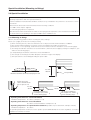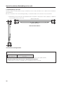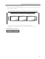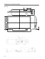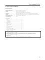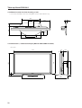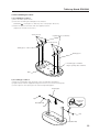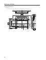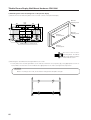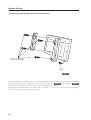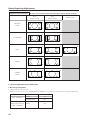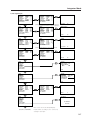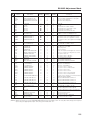
1
TECHNICAL MANUAL (Ver. 2.0)
PLASMA DISPLAY MONITOR: PDP-502MX
TABLE-TOP STAND: PDK-5001
PLASMA DISPLAY CEILING SUSPENSION HARDWARE: PDK-5002
PDP BRACKET: PDK-5005
PLASMA DISPLAY WALL-MOUNT HARDWARE: PDK-5006
CARRIABLE STAND: PDK-5008
SPEAKER SYSTEM: PDP-S03-LR
This manual provides precautions and information for installation, preparation, and handling of the plasma display and
its dedicated mounting hardware.
Before installation and preparatory work, choose a safe and appropriate site after thorough consideration of construction,
materials used, strength, and surroundings. If adequate safeguards are not in place, immediately halt the installation
process and discontinue marketing activities.
CAUTION
Exclamation marks placed within triangles are
intended to alert users to the presence of important
safety information. Be sure to read instructions
indicated by this symbol.
ABOUT MOUNTING/INSTALLATION
÷ This product is sold under the assumption that
installation will be performed by experienced,
qualified experts. Refer all mounting and
installation work to qualified personnel, or consult
the nearest PIONEER dealer for assistance.
÷ We accept no responsibility for accident or loss
resulting from failure to select an appropriate
installation site, or for those occurring during
assembly, installation, mounting, or operation of
this product, or resulting from modifications made
to this product, or from natural disasters.
PRECAUTIONS:
• We accept no responsibility for losses resulting from
the use of parts other than those supplied by us.
• We guarantee the performance of our products only
when they are assembled and adjusted as described in
this manual.
• The specifications and external designs shown in this
manual are subject to change without notice.
Table of Contents
FEATURES ..................................................................................................................................................................................... 4
SPECIFICATIONS
2.1 Specifications ..................................................................................................................................................................... 6
2.2 External Dimensions .......................................................................................................................................................... 8
2.3 Controls and Connectors .................................................................................................................................................. 10
2.4 Pin layout .......................................................................................................................................................................... 12
2.5 Remote Control Unit ........................................................................................................................................................ 13
2.6 Remote Control Unit Case ............................................................................................................................................... 14
INSTALLATION SITE REQUIREMENTS
3.1 Installation Site Requirements ......................................................................................................................................... 16
3.2 Installation Conditions ...................................................................................................................................................... 18
3.2.1 Heat dissipation ....................................................................................................................................................... 18
3.2.2 Calculating heat quantity ......................................................................................................................................... 19
3.2.3 Product mounting holes .......................................................................................................................................... 19
3.2.4 Mounting surface warping ...................................................................................................................................... 21
3.3 Installation Procedures ..................................................................................................................................................... 22
3.3.1 Transportation precautions ...................................................................................................................................... 22
3.3.2 Unpacking ................................................................................................................................................................ 22
3.3.3 Mounting on the attachment stands ....................................................................................................................... 23
3.3.4 Re-packing ............................................................................................................................................................... 23
3.3.5 Wiring ...................................................................................................................................................................... 24
3.4 Special Installation ............................................................................................................................................................ 26
3.4.1 Mounting to fittings ................................................................................................................................................. 26
3.4.2 Hanging on the wall ................................................................................................................................................. 28
3.4.3 Embedding in the wall ............................................................................................................................................. 30
3.4.4 When the display is put in a box ............................................................................................................................. 34
3.4.5 Ceiling suspension (with wires) ............................................................................................................................... 36
3.4.6 Hanging on the wall (lengthwise) ............................................................................................................................ 38
3.4.7 Place product upright and flush into wall (embedding in the wall) .......................................................................... 40
3.4.8 Horizontal connections ............................................................................................................................................ 44
3.4.9 Multiple ................................................................................................................................................................... 46
HOW TO USE THE STANDARD MOUNTING COMPONENTS
4.1 Standard Mounting Components Features and Characteristics ....................................................................................... 47
4.2 Handling the Standard Mounting Components ................................................................................................................ 48
4.2.1 Handling precautions ............................................................................................................................................... 48
4.2.2 Precautions for installation contractors ................................................................................................................... 48
4.3 Installation of the Attachment Stand ................................................................................................................................ 49
4.4 Table-top Stand: PDK-5001 .............................................................................................................................................. 51
4.4.1 Specifications .......................................................................................................................................................... 51
4.4.2 Mount locations for floor-fastening screws ............................................................................................................. 52
4.4.3 Dimensions ............................................................................................................................................................. 52
4.4.4 Assembling the stand .............................................................................................................................................. 53
4.4.5 Mounting to the main unit ....................................................................................................................................... 54
4.5 Plasma Display Ceiling Suspension Hardware (one-side type): PDK-5002 ....................................................................... 55
4.5.1 Specifications .......................................................................................................................................................... 55
4.5.2 External Dimensions ............................................................................................................................................... 56
4.5.3 Assembling and Installing the mounting hardware and mounting the plasma display ............................................ 57
4.6 PDP Bracket: PDK-5005 ................................................................................................................................................... 61
4.6.1 Specifications .......................................................................................................................................................... 61
4.6.2 External Dimensions ............................................................................................................................................... 62
4.6.3 Assembly Procedure ............................................................................................................................................... 63
4.6.4 An example of use .................................................................................................................................................. 64
4.7 Tiltable Plasma Display Wall-Mount Hardware: PDK-5006 ............................................................................................... 65
4.7.1 Specifications .......................................................................................................................................................... 65
4.7.2 External Dimensions ............................................................................................................................................... 66
4.7.3 Assembling the mounting hardware and mounting the plasma display ................................................................. 67
4.8 Carriable Stand: PDK-5008 ............................................................................................................................................... 71
4.8.1 Specifications .......................................................................................................................................................... 71
4.8.2 External Dimensions (with plasma display monitor PDP-502MX mounted) ............................................................ 72
4.8.3 Mounting procedures .............................................................................................................................................. 73
4.9 Speaker System: PDP-S03-LR .......................................................................................................................................... 75
4.9.1 Specifications .......................................................................................................................................................... 75
4.9.2 External Dimensions (with plasma display monitor PDP-502MX mounted) ............................................................ 75
4.9.3 Mounting to the main unit ....................................................................................................................................... 76
4.9.4 Mounting with the plasma display ceiling suspension hardware (PDK-5002) ......................................................... 78
4.9.5 Mounting with PDK-5006 (wall -mounting hardware) ............................................................................................. 80
BEFORE BEGINNING ADJUSTMENTS
5.1 Before Beginning Adjustments ........................................................................................................................................ 83
5.1.1 Operating mode ...................................................................................................................................................... 83
5.1.2 Combination use of remote control unit, operating panel and PC ........................................................................... 84
5.1.3 Lists of supported input signals .............................................................................................................................. 85
5.1.4 List of adjustable and settable items ....................................................................................................................... 88
5.1.5 Last memory ........................................................................................................................................................... 91
5.1.6 Aging ....................................................................................................................................................................... 91
2
Table of Contents
5.2 Normal Operating Mode ................................................................................................................................................... 93
5.2.1 About normal operating mode ................................................................................................................................. 93
5.3 Menu Mode ..................................................................................................................................................................... 94
5.3.1 About menu mode .................................................................................................................................................. 94
5.3.2 Example of menu mode operation .......................................................................................................................... 95
5.3.3 Settings in menu mode ........................................................................................................................................... 97
1) Setting power save ....................................................................................................................................... 97
2) Setting the color system ............................................................................................................................... 98
3) Setting the three-dimensional Y/C separator ................................................................................................ 99
4) Setting HIGH CONTRAST ........................................................................................................................... 100
5) Setting up peripheral equipment ................................................................................................................. 101
6) Setting the input signal format .................................................................................................................... 102
7) Setting the clamp position .......................................................................................................................... 103
8) ABL ON/OFF ............................................................................................................................................... 104
9) H / V enhancement tuning .......................................................................................................................... 105
5.3.4 Menu layers ........................................................................................................................................................... 106
5.4 Integrator Mode ............................................................................................................................................................. 108
5.4.1 About the integrator mode .................................................................................................................................... 108
5.4.2 Example of integrator mode operation .................................................................................................................. 109
5.4.3 Adjustments and settings in the integrator mode ................................................................................................. 111
1) Adjusting the PICTURE ............................................................................................................................... 111
2) Adjusting the WHITE BALANCE ................................................................................................................. 112
3) Adjusting the SCREEN ................................................................................................................................ 113
4) Adjusting the side mask .............................................................................................................................. 114
5) Setting the color mode ................................................................................................................................ 115
6) Setting the mirror mode .............................................................................................................................. 116
7) Setting the brightness enhancement at the screen center ......................................................................... 117
8) Setting OSD display .................................................................................................................................... 118
9) Setting the baud rate ................................................................................................................................... 119
10) Setting FULL MASK .................................................................................................................................... 120
11) Setting the cooling fan control formula ....................................................................................................... 121
12) Checking the inside temperature ................................................................................................................ 122
13) Checking the accumulated ON time ........................................................................................................... 122
14) Adjusting SUB VOLUME ............................................................................................................................. 123
15) Initializing Adjustments (ALL DEFAULT) ..................................................................................................... 125
5.4.4 Menu layers ........................................................................................................................................................... 126
5.4.5 PICTURE and WHITE BALANCE adjustment values memory area tables ............................................................ 128
5.4.6 SCREEN adjustment values area tables ................................................................................................................ 130
5.5 RS-232C Adjustment Mode ........................................................................................................................................... 131
5.5.1 About the RS-232C adjustment mode .................................................................................................................. 131
5.5.2 Interface ................................................................................................................................................................ 132
5.5.3 ID assignment ....................................................................................................................................................... 133
5.5.4 List of RC-232C commands .................................................................................................................................. 134
5.5.5 About the GET commands .................................................................................................................................... 136
5.6 Combination Connection ................................................................................................................................................ 138
5.6.1 Connections .......................................................................................................................................................... 138
5.7 KEY LOCK/UNLOCK ....................................................................................................................................................... 140
5.7.1 Functions ............................................................................................................................................................... 140
5.7.2 How to switch KEY LOCK/UNLOCK ..................................................................................................................... 140
5.8 Regarding the problem of images becoming burnt onto the screen ............................................................................. 141
OPERATING PRECAUTIONS AND RECOMMENDATIONS .................................................................................................... 142
6.1 Operating Precautions and recommendations ............................................................................................................... 142
MAINTENANCE AND CLEANING ............................................................................................................................................ 143
CAUTION
• To prevent injury and material damage, thoroughly read this manual and all labels found on the equipment before
attempting to mount, install, move, or adjust the product.
• Do not install the unit outside or in the open air. Doing so will lead to water seepage into the system, resulting in fire or
electric shock.
• Be especially careful when working around parts of the system that have sharp edges.
• When performing installation work from a height, take suitable precautions to guard against falling. Set up a barrier
around the work site to prevent accidentally dropped objects from injuring persons standing or walking below.
• Keep all foreign objects out of the unit. Do not tamper with the unit, or fire or electric shock may result.
• Observe the following operating environmental limitations:
Temperature: 0 to 40°C
Humidity: 20 to 80%
• Install the unit only in properly ventilated areas.
3
Features
Features and Functions of the PDP-502MX Plasma Display
High definition, high contrast
• Through the newly-developed panel that aims for the optimum in luminous efficiency and development of a new
drive sequence, we have achieved high contrast and a great improvement in brightness while maintaining high
definition.
High quality, clear picture
• By digitalizing the signal processing circuit, we have made possible clear, precise image representation for all
types of input signal (PC, video source etc.).
• Large screen with a built-in 8x-density IP converting circuit that results in high-quality video playback.
Thanks to High Vision Progressive, the picture is clearer than ever before even with high vision TV signals.
• Designed especially to address the problem of the ghosting noise usually found in plasma displays, the PDP502MX eliminates all ghosting.
Full XGA display; may also be used with compression as an SXGA/UXGA display
• Built-in 50-inch high-detail 1280x768 pixel (total 980,000 pixels) panel.
• 640 x 400 pixel display; able to display PC signals* at anywhere from full 640 x 480 (VGA) resolution to 1024 x 768
(XGA) resolution; may also be used at 1280 x 1024 (SXGA) resolution or 1600 x 1200 (UXGA) resolution.
Full 1280x768 pixel display is also possible if the dedicated video card is used.
Also compatible with HDTV signals**.
* SXGA resolution requires display image compression or partial display. UXGA requires display image compression.
** For playback of HDTV signals TV broadcasts, a separate DTV set top box is required.
Free choice of installation layout & slim design
• Highly efficient heat-dissipation design not only makes it possible to operate the display in a wider range of
temperatures but also reduces the amount of ambient noise generated.
Can be installed in a wide variety of ways and in a wide variety of locations .
• Light and compact design resulting in a large 50-inch display that is the thinnest and lightest of its kind in the
industry. (Width: 98 mm; Weight: 40.3 kg.)
Packed full of features that make it ideal for business or public-address use
• Built-in integrator mode that allows more precise adjustment than ever before.
• Equipped with audio amplifier (2W + 2W).
• Equipped with ample I/O terminals (4 picture input systems, 2 picture output systems, 2 audio input systems, 1
audio output system, 1 speaker output system).
• Equipped with special power management system.
• Equipped with RS-232C terminal as an external control interface.
• Equipped with combination terminal that enables a number of display systems to be controlled together from a
single PC.
• Equipped with operating mode monitoring system.
• Horizontal/vertical and left/right image rotation which makes it possible to use the display in a wide variety of
different types of applications.
• Key-locking security provided to help prevent theft or unauthorized use.
• Color temperature (white balance) switching function is provided for retakes.
• OSD (On Screen Display) ON/OFF Function
4
Features
5
Specifications
2.1 Specifications
Light-emitting panel .................. 50-inch plasma display panel
Aspect ratio .................................................................... 16 : 9
PEL .......................................................................... 1280 × 768
PEL pitch ........................... 0.858 (H•RGB trio) × 0.808 (V) mm
Gradation ..................................... 256/16.77 million full colors
Viewing angle .................. Horizontal: more than 160 degrees
Vertical: more than 160 degrees
Video-related
Input/output terminals
INPUT 1 Input
BNC terminal
Composite video signal
........................ 1 Vp-p/75 Ω/sync negative
Output BNC terminal ................... 75 Ω/with buffer
INPUT 2 Input
(NOTE 1)
1 S terminal (Mini-DIN, 4-pin connector)
2 BNC terminal × 2
Y/C separate video signal (for S2)
Y ...... 1 Vp-p/75 Ω/sync negative
C ...... 0.286 Vp-p/75 Ω (NTSC)
0.3 Vp-p/75 Ω (PAL)
INPUT 3 Input
BNC terminal × 5
1 RGB signal (for G ON SYNC)
R,G,B ............ 0.7 Vp-p/75 Ω/no sync
G ON SYNC .. 1 Vp-p/75 Ω/
sync negative
HD/CS.VD
TTL level (1 to 5 Vp-p)/
positive and
negative polarity/
75 Ω or 2.2 kΩ (with
impedance switching)
2 Component video signal
Y ......... 1.0 Vp-p/75 Ω/sync negative
PB/CB, PR/CR ... 0.525 Vp-p/75 Ω
(75% degree of saturation)
INPUT 4 Input
Mini D-sub, 15-pin connector (female)
1 RGB signal (for G ON SYNC)
R,G,B ............ 0.7 Vp-p/75 Ω/no sync
G ON SYNC .. 1 Vp-p/75 Ω/
sync negative
HD/CS.VD
TTL level (1 to 5 Vp-p)/
positive and
negative polarity/
2.2 kΩ
2 Component video signal
Y ........ 1.0 Vp-p/75 Ω/sync negative
PB/CB, PR/CR ............ 0.525 Vp-p/75 Ω
.......... (75% degree of saturation)
* Microsoft Plug & Play (VESA DDC 1/2B) supported
Output
6
Mini D-sub, 15-pin connector (female)
.......... 75 Ω/with buffer
Audio-related
AUDIO INPUT
(for INPUT 1/2)
Input
Pin jack (× 2)
L/R .... above 500 mVrms/10 kΩ
AUDIO INPUT
(for INPUT 3/4)
Input
Stereo mini jack (× 2)
L/R .... above 500 mVrms/10 kΩ
AUDIO OUTPUT
Output Stereo mini jack
L/R .... below the upper limit of
500 mVrms (national)/5 kΩ
SPEAKER
Output L/R .... 8 to 16 Ω /2 W + 2 W (when 8 Ω)
Control-related
RS-232C terminal: D-sub, 9-pin (male)
Combination In/Out Terminal: Mini-DIN, 6-pin
Control In/Out Terminal: Monaural mini-jack (× 2)
Power requirements ................. AC 100 V to 120 V, 50/60 Hz
In-rush ............................................................... less than 30 A
Power factor .................................................... more than 0.95
Consumption ......................... 470 W (NOTE 3) (0.6 W in standby)
External dimensions (without attachment stand)
.......................................... 1218 (W) × 714 (H) × 98 (D) mm
47-31/32 (W) × 28-1/8 (H) × 3-7/8 (D) in.
Weight (without attachment stand) ......................... 40.3 kg
(88 lbs. 14 oz)
Dimensions of packaging .. 1341 (W) × 890 (H) × 424 (D) mm
52-13/36 (W) × 35-1/16 (H) × 16-23/32 (D) in.
Weight when packaged .................................................. 53kg
(116 lbs. 14 oz)
Operating Temperature ................................. 0 to 40 °C (NOTE 4)
(32 to 104 °F)
Operating Humidity .............................................. 20 to 80 %
Operating atmospheric pressure ..................... 0.8 to 1.1 atm
Storage limitations (when installed)
Temperature .................................................. –20 to +60 °C
(–4 to 140 °F)
Humidity ............................................................. 20 to 90 %
Atmospheric pressure .................................... 0.6 to 1.5 atm
Storage limitations (when in original package)
Temperature .................................................. –40 to +60 °C
(–40 to 140 °F)
Humidity ............................................................. 20 to 90 %
Atmospheric pressure .................................... 0.6 to 1.5 atm
Stacking ............................................ Fewer than three tiers
Standard accessories
Power cord .............................................................................. 1
Remote control unit ................................................................ 1
AA battery ............................................................................... 2
Pin/BNC conversion adapter ................................................... 1
Wiping cloth ............................................................................ 1
Speed clamp ........................................................................... 2
Bead Band ............................................................................... 2
Operating instructions ............................................................. 1
Warranty card .......................................................................... 1
Remote control unit case ........................................................ 1
Display stand ........................................................................... 2
Large washer .......................................................................... 2
Small washer .......................................................................... 2
Hexagon socket head screw ................................................... 2
Specifications and external designs are subject to change without
notice.
Specifications
(NOTE 1)
(NOTE 2)
(NOTE 3)
(NOTE 4)
Do not make connections to the S terminal and a BNC terminal at the same time. This could cause malfunction or
breakage of the device.
The display is preset at the factory to 4800bps. This setting can be changed using either the remote control unit or a PC.
Allow for 500 W ≠ 500VA of consumption per unit.
The correct operating environmental temperature may vary, depending on the installation site. (Refer to Installation Site
Requirements.)
INPUT Response Signals
INPUT 1: Composite video signal NTSC, PAL, SECAM, 4.43 NTSC
INPUT 2: Y/C Separate video signal NTSC, PAL, SECAM, 4.43 NTSC
INPUT 3, 4
& Video signals supported
Vertical
Frequency
Fv (Hz)
Horizontal
Frequency
Fh (kHz)
Signal Format
Component
RGB
Component
RGB
Component
RGB
Component
RGB
Component
RGB
Component
RGB
Component
RGB
15.625
50
31.25
15.734
31.5
60
33.75
45.0
67.5
Remark
480i(SDTV)
480p(SDTV)
1080i(HDTV)
HDTV signal
720p(HDTV)
1080p(HDTV)
& PC signals supported
Caution : These signals are tested to work correctly. Other signal frequencies than listed may couse undesirable images.
Resolution
(Dot x Line)
Vertical
Frequency
Horizontal
Frequency
640 x 400
56.4Hz
70.1Hz
24.8kHz
31.5kHz
640 x 480
60Hz
31.5kHz
800 x 600
832 x 624
1024 x 768
66.7Hz
35.0kHz
72Hz
75Hz
85Hz
56Hz
60Hz
72Hz
75Hz
85Hz
37.9kHz
37.5kHz
43.3kHz
35.2kHz
37.9kHz
48.1kHz
46.9kHz
53.7kHz
74.6Hz
43Hz
Interlace
60Hz
70Hz
49.7kHz
Remark
NEC PC-9800
NEC PC-9800
(852 x 480)
(864 x 480)
Apple
Macintosh 13"
(1072 x 600)
75Hz
(74.9Hz)
60.0kHz
(60.2kHz)
85Hz
68.7kHz
Vertical
Frequency
Horizontal
Frequency
60Hz
72Hz
75Hz
53.7kHz
64.9kHz
67.7kHz
1152 x 870
75.1Hz
68.7kHz
Apple
Macintosh 21"
1152 x 900
66.0Hz
61.8kHz
Sun Microsystems LO
76.0Hz
71.7kHz
Sun Microsystems HI
56Hz
60Hz
43Hz
Interlace
60Hz
75Hz
85Hz
60Hz
65Hz
70Hz
45.1kHz
60.0kHz
1152 x 864
1280 x 768
1280 x 960
1280 x 1024
Apple
Macintosh 16"
35.5kHz
48.4kHz
56.5kHz
Resolution
(Dot x Line)
1600 x 1200
(1376 x 768)
Remark
46.4kHz
64.0kHz
80.0kHz
91.1kHz
75.0kHz
81.3kHz
87.5kHz
(1600 x 1024)
Figure in
brackets are
for Apple
Macintosh 19"
7
External Dimensions
2.2 External Dimensions
Weight: 40.3 kg (without attachment stand)
Material: Front: Resin; Rear frame: Resin; Rear cover: Aluminum, Front protector panel: acrylic
Treatment: Front: Paint; Rear frame: Paint; Rear cover: Paint (All paints are Pioneer original colors)
For packaging information, refer to 3.3.2 “Unpacking”.
31.4
: Center of gravity
(Unit: mm)
98
609
65
1218
1098
Effective screen dimensions
)
91
(12
620.5
1128
357
628
714
Effective screen dimensions
Unit operating
panel
Light sensor for the remote
MAIN POWER switch
Centering
900
Terminal area dimensions
Rear View
1162
590
104
250
150
660
150
250
104
496
2-M8 (special screw for anchoring plain stand)
18-M8 (φ 16 mm, with hole rivet)
8
External Dimensions
<Main Unit Operation Panel>
11
<Light Sensor for the Remote>
7.8
STANDBY/ON
INPUT
11.1
MENU
146.6
ADJUST
SET
SIZE
DISPLAY
48.1
22.5
29.8
21.4
9
Controls and Connectors
NOTE
When the optional plasma display speakers are attached, it is
not possible to use the operation panel on the display.
2.3 Controls and Connectors
<Operation Panel>
STANDBY/ON
INPUT
MENU
1
2
3
4
5
ADJUST
6
SET
SIZE
DISPLAY
0
R
SPEAKER
8Ω ~16Ω
-
=
IN
AUDIO OUTPUT
~
OUT
IN
COMBINATION
OUT
CONTROL
!
@
#
R
RS-232C
INPUT 3/4
L
INPUT 1/2
AUDIO INPUT
^
Y
G
ON SYNC
& * ( )
CB/PB
CR/PR
B
R
HD
INPUT 3
H/V SYNC
75Ω
2.2kΩ
VD
S-VIDEO
_
Y
INPUT 2
+ ¡
C
$
%
ANALOG
R G B
INPUT 4
OUTPUT
ANALOG
R G B
™
VIDEO
OUTPUT
INPUT 1
INPUT 1
7
8
9
<Connectors>
(at the rear of the
main unit)
£
¢
SPEAKER
8Ω ~16Ω
MAIN POWER
OFF
L
AC INLET
ON
<Main Power Switch Section>
9 DISPLAY button
1 STANDBY/ON indicator
Used to view input and settings conditions.
Red when the display is in standby mode; turns green
when the display is operational.
<Terminal Section>
2 STANDBY/ON button
Turns main power on or off.
Output terminal for a right-hand external speaker.
Connected to speakers of 8 to 16 Ω impedance.
3 KEY LOCK/UNLOCK switch (hidden)
- AUDIO OUTPUT (Stereo mini jack)
Renders the operation panel and remote operative or
inoperative.
Used to output the sound from a device connected to the
display to a device such as an AV amplifier.
4 INPUT button
Used to select inputs.
= Combination Input and Output Terminals
Used for simultaneous control of various units.
5 MENU button
(Refer to 5.6 “Combination Connection”.)
Please use a Mini DIN 6-pin cable (straight, all pins wire
Used to display the menu screen.
6 ADJUST (5∞32) buttons
Used to move the cursor on the menu screen or to
increase/decrease adjustment values.
7 SET (select) button
Used to select an adjustment item on the menu screen
or to change settings.
8 SIZE button
Used to manually change screen size.
10
0 SPEAKER
bound; this is readily available on the market) as the
connector cable.
(NOTE) No ABL linkage function is provided.
These terminals are incompatible with multiprojections such as the RM-V4000V.
When the main power is off, there is no output.
Controls and Connectors
~ CONTROL IN/OUT terminals
( Sync Signal Impedance switch
For connection to Pioneer products that have the Î mark.
If you connect a CONTROL (If CONTROL connection is
Used to switch impedance for items & and *.
carried out) then you can carry out system control of the
display.
INPUT 2
(NOTE) This product does not support RU-V107 wired
remote control units.
_ Y/C Separate Video Input terminal
Receives signals from the Y/C separate video.
! RS 232C terminal
(Supports S2 output.)
Used to make adjustments from PC. (Conforms to EIA232-F.)
(Refer to 5.5 RS-232C Adjustment Mode.)
) S-VIDEO input terminal
(NOTE) Don't connect the S-jack and the BNC
terminal at the same time. Doing so will
result in system malfunctions or
breakdown.
@ AUDIO INPUT (Stereo mini jack)
Audio input for use when the picture input uses INPUT 3
or INPUT 4. Connect to the audio output terminal of the
device that is connected to INPUT 3 or INPUT 4 of the
display.
INPUT 1
# AUDIO INPUT
Outputs signals received by the video input terminal.
Audio input for use when the image input uses INPUT 1
or INPUT 2. Connect to the audio output terminal of the
¡ Video Output terminal
device that is connected to INPUT 1 or INPUT 2 of the
display.
+ Video Input terminal
Video input terminal (+) are output from this terminal.
Will not output when the power is off or in standby status.
(NOTE) When connecting this unit, take a total
INPUT 4
$ INPUT 4 input terminal
Used to input an analog RGB signal or a component picture
signal.
(NOTE) Also supports Green on Sync.
This terminal supports Microsoft Plug & Play (VESA DDC
1/2B).
% INPUT 4 output terminal
Signals fed to the INPUT 4 input terminal ($) are output
from this terminal. No signal is sent when power is
switched off, or in standby status.
of five other units as the standard number
that can be set to receive input from it.
™ Main Power switch
Turns the main power on or off.
£ AC INLET
Using the power cord accessory, connects to the AC
power source.
¢ SPEAKER
Output terminal for a left-hand external speaker.
Connected to speakers of 8 to 16Ω inpedance.
(NOTE) When connecting this unit, take a total
of five other units as the standard number
that can be set to receive input from it.
However, when inputting/outputting to/
from separate sync or composite sync,
the source sync level at the end terminal
must be 2.2 kΩ, and over 4.8 Vp-p.
INPUT 3
^ G(Y)/B(CB/PB)/R(CR/PR)
Receives signals from RGB or video hardware.
(NOTE) Also supports Green on Sync.
& HD (H/V SYNC)
Receives signals of HD, and H/V Sync.
* VD
Receives a VD signal.
11
Controls and Connectors
2.4 Pin layout
INPUT 4 (Mini D-sub, 15-pin connector; female)
pin layout
RS-232C terminal (D-sub 9-pin connector; male)
pin layout
Note : Standard VGA connector (plug and play supported).
Note : Plasma communicates as a DCE derice.
5
1
1
5
6
10
15
11
Pin No. $ INPUT4 input terminals
6
% INPUT4 output terminals
9
Signal
Pin No.
1
R or CR/PR
1
NC (not connected)
2
G or Y
2
TxD (Transmit Data)
3
B or CB/PB
3
RxD (Receive Data)
4
NC (not connected)
4
NC (not connected)
5
GND
5
GND
6
GND
6
NC (not connected)
7
GND
7
NC (not connected)
8
GND
8
RTS (Request To Send)
9
NC (not connected)
NC (not connected)
9
DDC +5V
10
GND
NC (not connected)
11
NC (not connected)
12
DDC SDA
13
HD or H/V SYNC
14
VD
15
DDC SCL
NC (not connected)
NC (not connected)
Combination IN/OUT terminal pin layout
Pin No.
6
5
4
3
2
1
Combination
Combination
IN
OUT
1
GND
GND
2
Remote control (input)
Remote control (output)
3
TxD (output)
RxD (input)
4
NC (not connected)
NC (not connected)
5
RxD (input)
TxD (output)
6
NC (not connected)
NC (not connected)
12
Remote Control Unit
2.5 Remote Control Unit
SCREEN SIZE button
Used to manually select the
screen size.
STANDBY
SCREEN
/ON
STANDBY/ON button
Used to turn the system on or off
(standby).
INPUT button
Used to select inputs.
MUTING
SIZE
INPUT
VIDEO
Y/C
1
2
RGB
RGB
(BNC)
(D-sub)
3
4
VOL
MUTING button
Used to temporarily turn off the
sound.
DISPLAY
MENU
VOL buttons (+/–)
Used to adjust the volume.
DISPLAY DISPLAY button
MENU button
Used to display the menu screen.
Used to view condition of inputs
and settings.
SET
SET (select) button
Used to select the item to be
adjusted on the menu screen. Used
Î
to change the various settings.
Adjustment buttons
(5∞32)
Used to move the cursor on the menu
screen, or to adjust various settings.
13
Remote Control Unit Case
2.6 Remote Control Unit Case
Peel the sticker paper off of the lower and upper tape on the rear side of the remote control unit case, and attach it to
the rear of the main unit or some other fixed surface, so that it will be available for putting away the remote control unit
when it is not in use.
Remote control unit
Example of remote control
unit case attachment
Remote control
unit case
Upper and lower tape
(NOTE) Do not obstruct the air holes in the remote control unit case.
14
Remote Control Unit Case
15
Installation Site Requirements
3.1 Installation Site Requirements
If the site requires modifications or special preparations for installation of the plasma display or its mounting hardware,
obtain permission in advance from the building owner or building authorities. To ensure installations safety, it is also
important to determine the strength of the installation site with the help of the original building contractor.
Safety Precautions
1) Structure of the installation site
Make sure you thoroughly understand the structure of the installation site before determining the most suitable installation
method. Buildings vary in structure and materials, and the appropriate mounting hardware with differ accordingly.
When drilling into walls, always remain aware of the internal electric wiring and pipes.
2) Weight capacity of the installation site
Select a location with a weight capacity sufficient to support the total weight of the display and mounting hardware.
3) Flat, level surfaces
Select a flat, level surface for installation, such that mounting software will be parallel to the surface to which it is
affixed.
Install the unit so that the load is evenly distributed along the ceiling or floor, as well as on mounting hardware such as
hang bolts.
4) Sufficient work space
Select a location with sufficient space for installation work. The installation work should be conducted by two or more
persons.
5) Nearby equipment
If air conditioning ducts or lamps, etc. are located near the installation site, the attendant dust, extreme temperatures,
humidity, and condensation may become sources of trouble. Please take sufficient steps to avoid this.
6) Safe locations
Do not install the unit where it may be easily touched or leaned against. Avoid locations subject to high vibration or
severe impacts.
7) Lighting conditions
• Consider existing lighting and sunlight angles when creating the installation layout. Extremely bright lighting can
reduce the visibility and quality of the display image.
• In extremely bright surroundings, adjusting screen intensity may not result in perceptibly brighter images. Keep in
mind that extreme intensity settings can reduce system service life.
8) Installation partially outdoors
The unit is designed for indoor use, and is not suited for open-air use. Installation in locations that are even partially
exposed to the elements may lead to malfunctions or breakdown caused by any of the following:
• Water and dust
• Changes in temperature and humidity
• Salt-bearing wind
Direct sunlight upon the display degrades image quality. In installing the display, avoid sites exposed to direct sunlight.
16
Installation Site Requirements
9) Temperature and humidity conditions
• The installation site should meet the following conditions:
• Operating temperatures: 0 to 40 °C (largely depending on installation conditions)
•
•
Operating humidity: 20 to 80 %
Storage temperature: –20 to 60 °C
•
•
Storage humidity: 20 to 90 %
Operating atmospheric pressure: 0.8 to 1.1 atm
•
Storage atmospheric pressure: 0.6 to 1.5 atm
• We recommend against installing electronic products such as this unit in locations subject to high humidity. If the unit
is to be installed in a location subject to relatively high humidity, observe the following:
•
•
Failure to install the unit in unacceptable ways may result in non-warranty damages.
Make sure the unit is grounded.
•
Do not allow water or other liquids to enter the unit.
10) Prevent condensation
One of the chief sources of problems during the winter is “condensation”. Rapid temperature fluctuations can deposit
water vapor inside the unit or on the screen, degrading performance. If condensation occurs, turn the unit off and leave
it off for an hour or so. It is also good practice to increase the room temperature gradually.
Beware of condensation. Consult Pioneer authorized dealers for assistance.
11) Power requirements
• This unit functions properly when powered at ±10 % of its rated voltage. Characteristics of power lines may effect
the voltage output. If any of the following occurs, contact an electrician to inspect the power.
• Significant voltage drop between the circuit panel and the plasma display
• Significant changes in voltage when switching the unit power on or off
• When calculating power consumption, allow for 500 W ≠ 500 VA of consumption per unit.
(NOTE)
• The in-rush current upon powering will be approximately 30 A.
12) Effective remote control distance
This display emits weak infrared radiation. If other products controlled with infrared remote controls are placed nearby,
remote control function may be affected. In such cases, move them further away from the display or contact Pioneer
authorized dealer for assistance.
Depending on installation conditions, the range of the unit's own remote control may be reduced by infrared radiation
emitted by the screen.
The screen's infrared intensity will vary, depending on the image displayed.
17
Installation Conditions
3.2 Installation Conditions
3.2.1 Heat dissipation
This unit has openings for effective ventilation at locations marked by arrows in the illustration below. To allow proper
dissipation of heat from the unit, avoid blocking or covering any of these openings.
(Unit : mm)
60
157
80
80
128
119
72
59
80
168
19
45
282.5 (one side only) 53
160
256
453
53
190
183
247.5
142.5
72.5
54 38
119
19
269
119
537.5
Fan (4 in number)
137.5
160
235
Air flow through the openings: All four fans draw off hot air from the unit. All openings not assisted by fans serve as
air inlets. If the unit is hung from or embedded into a wall, special operating temperature limits and other limitations
may apply. Refer to 3.4 “Special Installation”.
18
Installation Conditions
3.2.2 Calculating heat quantity
As a curtesy to our customers, we have included the power formula to calculate the air conditioning needs.
For power consumption, allow for 500 W ≠ 500 VA per unit.
Since most of the power consumed is transformed into heat, power consumption may be regarded as roughly equal to
generated heat.
1 Conversion to calories
[W] × 0.86 = [kcal/h]
Heat generated per display: 500 W × 0.86 = 430 kcal/h
2 Conversion to British Thermal Units
[W] × 3.41 = [BTU/h]
Heat generated per unit: 500 W × 3.41 = 1705 BTU/h
3.2.3 Product mounting holes
We recommend using mounting hardware available from Pioneer. If you use other mounting hardware items, mount
them to the unit using the M8-bolt holes provided in the unit. Remove the hole rivets, depending on the particular
mounting hardware used. Tighten the bolts with a torque between 50 and 80 kg/cm. Applying a torque beyond these
limits may lead to internal component failure.
• Locations of useable mount holes are shown below. (Caps or plugs can be removed by turning them with a coin or
other device.)
Air holes (Fan)
Hole "b"
Hole "b"
Hole "a": in 6 locations
Hole "b": in 14 locations
Mounting Surface
Mount
hardware, etc.
The main
unit
Center
Line
Hole "b"
Hole "a" Hole "a"
Hole "b"
Hole "a"
Bolt
12 to 20 mm
Hole "b"
Bolt
Hole "b"
Center
Line
12 to 20 mm
Hole "b"
Rear View
Side View
Always use a minimum of 4 mounting holes, evenly distributed on opposite sides of both the horizontal and
vertical center lines.
Use bolts that can be driven 12 to 20 mm into holes "a" or "b", as shown in the Side View above.
Do not block or cover air outlets and openings for ventilation on the rear panel.
Take precautions to prevent soiling walls behind the product with exhaust air discharged from the air outlets.
This unit incorporates glass components. Install only on flat surfaces.
Always turn every bolt by hand 2 or 3 times and check to make sure it is straight, then tighten it using a tool.
Do not over tighten bolts.
Do not use loctight or similar bonding products.
Please make sure that you use M8 (P=1.25) bolts. (other types of bolt cannot be used).
19
Installation Conditions
This unit is designed to be mounted using four bolt holes. For additional safety, we recommend securing it at six to
eight points on opposite sides of the horizontal and vertical center lines, as shown in the illustration below. Do not
secure the unit at four points arranged in a single row, as shown below.
Methods for securing - Unfavorable examples
Methods for securing - Favorable examples
A. Secured at eight points
B. Secured at six points
C. Secured at four points (with mounting hardware attached to the sides)
20
Installation Conditions
D. Secured at four points (with mounting hardware attached horizontally)
(Take proper precautions to prevent pinching the power cord or signal cables.)
3.2.4 Mounting surface warping
The display section incorporates glass. Before mounting the product, using hardware other than that provided by
Pioneer, perform the following to confirm that the display is free from warps exceeding 1 mm*.
* Regarding the 1mm limit
The frame of the display may have a warp of up to 3mm. If the total warp (the warp of the frame plus the warp of the
mount surface) exceeds 4mm then the glass in the display may be put under excessive stress. In order to ensure that
the total warp is less than 4mm, you should make sure that the warp of the mount surface is less than 1mm.
1 Referring to the illustration below, diagonally extend string of maximum φ 0.1-mm diameter through the bolt
mount openings. Strings thus arranged should be completely free of slack.
2 Measure the clearance (L) between the strings at their point of intersection.
Distortion is expressed by: [Distortion] = L × 2.
3 If L is found to be 0, pass the strings through the other bolt mount openings and repeat the measurements. Any
value of L greater than 0 indicates the presence of distortion. If the measured value in both cases is 0, the
distortion is negligible.
A
A
Mount bolt
holes
Plasma Display Mount Surface (Mount Brackets)
String A
D
Point E is the center point of string
segment A-B.
Point F is the center point of string
segment C-D.
Clearance between points E and F = L.
Points E and F are shown displaced
for illustrative purposes.
F
E
String
C
B
Magnified view of section A
21
Installation Procedures
3.3 Installation Procedures
3.3.1 Transportation precautions
1 Any transportation of the unopened unit in its packaging should be done by two or more persons. To avoid injury
or damage, do not lift the package by its packing bands.
2 When transporting or storing the unit, always position it vertically - never horizontally. Horizontal transportation or
storage invalidates the product warranty
3 In transportation or storage of products in original packing, never stack more than three units high. This warning
is also indicated on the upper face of the carton.
4 For transportation or storage, observe the warnings and instructions on the upper face of the carton.
5 Plasma display is mode off grass. Please take precations to prevent it from being dameged.
3.3.2 Unpacking
The original packing material can be re-used to sofely ship the Plasma Display. When doing so, it is important to use the
material in the same way as when they were originally shipped. Failure to correctly use the material can damage the
display.
1) Packing specifications: 1341 (W) × 890 (H) × 424 (D), 53 kg
Ref. No.
1
2
3
4
5
1
2
20
6
19
Terms
Upper face of the carton
Carton cover
Lower face of the carton
Upper pad L
Upper pad C
6
7
8
9
10
Upper pad R
Under pad L
Under pad C
Under pad R
Miller mat
11
12
13
14
15
Power cord
Remote control unit (CU-V159)
2 manganese AA batteries, R6P
Operating instructions
Guarantee
16
17
18
19
20
Warranty card
Binder Assembly
Wiping cloth
Front face of the carton
Rear face of the carton
21
22
23
Pin/BNC conversion connector
Power cord case
Display stand case
(with display stand inside)
Remote control unit case
Bolt, Washer
15
5
16
4
11
22
10
8
9
23
7
Tape
3
12
13
22
18
These accessories
shall be packed in
21
a bag, which then
shall be stuck to 19
(front carton) with
24
25 a piece of adhesive
tape.
14
17
24
25
Installation Procedures
2) Unpacking procedures
1 Remove the packing bands.
2 Slowly lift and remove the upper carton.
3 Lift and remove the carton cover.
4 Remove the L, C and R upper cartons.
5 Remove the front and rear cartons.
6 Remove the operating instructions and accessories, which are secured to the lower carton by adhesive tape.
7 Remove the unit. (This should be performed by two persons.)
3) Transportation of the unpacked unit.
If it needs to be moved, the unit should be lifted by two persons.
• Never move the unit by dragging it along the floor.
• Move the unit slowly, taking care to prevent scraping or striking the delicate front protective panel.
• In order to prevent adhesion of dust, remove the protective film only after all work and preparations for the
installation site, including clean-up following unpacking, are complete.
3.3.3 Mounting on the attachment stands (See 4.3 " Installation of the Attachment Stand" for instructions on permanent installation.)
Insert the stand bolt into holes A and A' so that the head of the bolt can slide into the slot in the stand.
Unpacking procedure stops at Step 2), 6, above. Bolts A and A' can be made to slide into the slot in the stand before
the unit is unpacked. This method should, insofar as possible, be a temporary setup pending proper installation.
When installing the attachment stand, consult 4.3 “Installation of the Attachment Stand”. If making the attachment
to position B, use the B hole rivet, or remove the A stand bolt and attach it to position B.
Placing the screen on the stands is only a temporary step before proper installation. We cannot guarantee against
damage to the screen caused by it toppling over under an external force etc. while it is placed on the stands.
B A
A' B
3.3.4 Re-packing (re-packing and re-shipping are not covered by the warranty.)
If the unit needs to be re-packaged, observe the following guidelines.
• Pack by performing in reverse order the steps described in 3.3.2 “Unpacking”. The miller mat must be positioned
so that the shiny film surface faces outward and its soft surface faces inward (toward the unit).
• Restore all accessories to their original locations. Secure with adhesive tape to prevent damage during
transportation.
• Do not re-package and ship if the packing material is damaged.
23
Installation Procedures
3.3.5 Wiring
1) Connecting the power cable
• Refer to the section on Power Cord Connection on p. 16 of the operating instructions.
• For power source specifications, refer to 3.1 “Installation Site Requirements”, Section 11) Power requirements,
above.
2) Connecting signal cables
(1) Please refer to p10~17 of the instruction manual for instructions on how to connect a PC or a video device.
(2) Important notes
• Use coaxial cables. As a rough guide, for video signals use 3C-2V cables for lengths up to 15 meters, and 5C2V cables for lengths up to 30 meters. Use thicker cables for computer signals, since these signals are more
likely to degrade: 5C-2V cables, for example, for 15-meter lengths. Generally, thicker cables will produce
more reliable connections. You can also improve signal quality by minimizing cable length.
• Video cables plugged into video inputs and outputs close to dimmers, neon signs, air-conditioning units, or
cables for wired broadcasts may occasionally deliver slightly corrupted images.
3) Processing wires
• In the case of permanent or long-term installation, please be careful to select cables of the correct length,
considering the whole wiring route when doing this (this is not so important in the case of short-term installation
such as with special events).
• Arrange and secure cables so that they will not be subject to direct load or physical force. For temporary
installation, securing cables with string should be perfectly adequate. For permanent installations, secure by
more reliable means.
24
Installation Procedures
4) Arranging and securing cables with speed clamps and bead bands
1 Fasten cables using the supplied speed clamps.
Remember that speed clamps are not easily
removed, once fastened.
2 Secure cables with the supplied bead bands.
* Display viewed from the rear.
Cables may be drawn around to the right, viewed from this side.
1 Secure cables with speed
2 Bundle cables using bead bands.
clamps.
Use the head band at
2
two positions within the
indicated range
.
1
Cords
Insert part 2 into an opening in the rear
cover, then insert part 1, as shown.
Fastening points for speed clamps
Bundled cables can be drawn to
the left or the right.
Depending
on
specific
requirements, you may use the
four opening indicated by solid
circles ¶.
How to unlock the speed clamp
Use a pair of pliers to twist
the clamp by at least a
quarter-turn and pull outward.
Remember that this procedure
entails risk of damaging the
clamp.
25
Special Installation (Mounting to fittings)
3.4 Special Installation
The unit can be hung from or embedded in a wall, but such special installations impose additional limitations on
operating temperatures and other operational factors.
Examine installation methods and the ambient conditions for your installation site, and refer to sections 3.1 to 3.3 in
this manual.
Measurements discussed in this manual assume the following conditions:
• A 100 % white input is supplied.
• Sufficient aging has been completed.
Make all measurements under identical conditions. The aging period required for correct measurement will be about
two and a half hours, depending on the space available at the installation site.
3.4.1 Mounting to fittings
Observe the following guidelines when mounting the unit to fittings.
Notes 2 to 7 apply to all cases of mounting to fitting.
1 When mounting the unit, make sure that there are no objects around it within a distance of 300mm.
2 Any unit deformation/warping occurring as a result of installation should be less than 4 mm.
3 Never block or cover openings, aside from those shown as blocked in the illustrations on the following page.
4 The fittings should have a thickness of less than 20 mm. (This limit does not apply to fittings in examples 2, 4, 6
and 8 on the following page.)
5 L-shaped fittings should have a thickness of less than 100 mm.
6 The strength of the fittings should be adequate to bear the weight of the display.
4 mm MAX
7 Take precautions to avoid sharply bending the power cable.
Less than
100 mm
L-shaped fitting
Maximum allowable deformation/warping is 4 mm.
Arrange the power
cable so that minimum
stress is placed on it.
Less than
20 mm
Less than
20 mm
No thickness limitations
in examples 2, 4, 6 and 8
on the following page.)
No thickness limitations
in examples 2, 4, 6 and 8
on the following page.)
✩ Operating environment for standard installation
• Ambient Temperature: 0 to 40 °C (examples 1 to 4)
✩ Operating environment for vertical installation
0 to 40 °C (vertical installation: examples 5 to 8)
✩ Operating temperatures for Upside-Down Installations (possible only for attachment examples 2 and 3)
• Ambient temperature: 0 to 40 °C
The operating temperature restrictions for the speaker system (PDP-S03-LR) are the same regardless of whether
installation is horizontal or vertical.
26
Special Installation (Mounting to fittings)
␣ Standard installation
(Note that only Examples 2 and 3 apply in cases where top and bottom are reversed)
Example 2
Example 1
35 mm or
less
Example 3
Example 4
35 mm or
less
* Never block this
opening.
Vertical installation
Example 5
Example 6
35 mm or
less
Attach with
this fan
upwards.
* Never block this
opening.
Example 7
Example 8
35 mm or
less
27
Special Instruction (Hanging on the wall)
3.4.2 Hanging on the wall
Carefully read the following before attempting to hang the unit on a wall, and observe the various limitations specified
below. Be sure to mount the unit so that twisting, bending, or any other deformation does not exceed 4 mm.
Shaded areas
indicate attachment
points for mounting hardware.
1218
67
67
45
45
54.5
714
43
B
A
10
C
Avoid blocking or covering this area on the upper and lower sides
25
D
D
Operating temperature restrictions
✩ Standard single-unit installation
* When attached using PDK-5005 PDP brackets, the distance A between the unit and the wall must be no
less than 50 mm.
B
C
D
50 mm or less
300 mm or more
300 mm or more
300 mm or more
0 to 35°C
50 mm or more
100 mm or more
50 mm or more
50 mm or more
0 to 40 °C
Distance from wall (A)
Ambient temperature
✩ Horizontal/vertical, left/right reverse installation (Note that only Examples 2 and 3 apply in cases
where top and bottom are reversed)
* No matter what the distance between the unit and the wall, the unit must be installed in such a way as
to ensure free air flow (With no obstructions within a distance of 300 mm from the unit).
Distance from wall (A)
None
B
C
D
300 mm or more
300 mm or more
300 mm or more
Ambient temperature
0 to 35°C
✩ Requirements when used with PDP-S03-LR speaker system
When installed as a single unit, all requirements are the same as those listed above for horizontal/
vertical, left/right reverse installation. Note, however, that the figures listed above are to be interpreted
as indicating the distance between the speakers and the wall.
(NOTE) Different temperature restrictions apply to the PDK-5006. Refer to 4.7 “Tiltable Plasma Display Wall- Mount
28
Hardware”. In wall-mounting installation, allow adequate space (a clearance of 300 mm or more) above and
below the monitor set, as well as to the right and left.
Special Installation (Hanging on the wall)
Methods of Securing: Basic methods of securing are shown below. Avoid blocking or covering areas aside from those
indicated by
. The method indicated by a large X-mark must not be used.
Before attaching the unit to fittings, double-check that the thickness and height of the fittings,
and the number of fixing bolts is correct.
(Also refer to 3.4.1 “Mounting to fittings”.)
NOTE 1
Heated air is drawn off from the interior of the unit by fans. Before installation, consider the heat resistance of the
wall or other surfaces behind the unit. Exhaust temperatures can be 30 °C higher than the outside temperature.
NOTE 2
For wall-mounting, do not bundle the cables in a way that will obstruct ventilation.
300 mm or
more
300 mm or
more
ÉpÉìÉ`ÉìÉOÉlÉbÉg
Panting net
50 mm or more
100 mm or more
50 mm or
more
50 mm or
more
50 mm or more
Ex.: Installation requirements when
installed in recess in wall
Ex.: Installation when covered with a
Panting net
Flush-wall installation
Wall-mounted installation
Wall-embedded installation
(distance between unit and wall
less than 50 mm)
(distance between unit and wall
greater than 50 mm)
(i.e., installation in closed space)
Requirements :
Requirements :
Requirements :
• Free air flow (With no obstructions
• Free air flow (With no obstructions within
• See 3.4.3 Embedding in the wall for
within a distance of 300 mm from
a distance of 300 mm from the unit)
the unit)
around all four sides of the unit is not
• Temperature of 0–35°C
installation requirements..
• Temperature of 0–40°C
necessarily required when the unit is
installed at a distance of greater than 50
millimeters away from the wall.
* Note, however, that in such cases the unit
may not be placed behind a glass panel or
any other obstruction which would create
a closed space.
• Temperature of 0–40°C
29
Special Installation (Embedding in the wall)
3.4.3 Embedding in the wall
Carefully read the following before trying to embed the unit in a wall, and make sure to observe all the limitations
specified below.
Be sure to mount the unit so that twisting, bending, or other deformation of the unit does not exceed 4 mm.
(1) Embedding in walls with space provided behind the unit (With no obstructions within a distance of 300 mm
from the back surface of the unit).
X (Front of the unit)
A
A
Y (Rear of the unit)
<Viewed from Above>
A
<Viewed from the Right Side>
✩ Operating Temperature Restrictions
A: 0 to 370 mm
Temperature in space X and Y
0 to 40 °C
* The same operating temperature restrictions apply to the speaker system (PDP-S03-LR).
✩ Operating Temperature Restrictions for Upside-Down Installations
␣ * Upside-down mounting is unavailable when embedding this device in a wall.
30
A
Special Installation (Embedding in the wall)
Methods of Securing: Basic methods of securing are shown below. Avoid blocking or covering areas aside from those
indicated by
. The methods indicated by a large X-mark must not be used.
Before attaching the unit to fittings, double-check that the thickness and height of the fittings,
and the number of fixing bolts is correct.
(Also refer to 3.4.1 “Mounting to fittings”.)
Temperature Measurement Points (Illustration for reference purposes)
50mm
50mm
• Make measurements at a distance of 5 cm from the unit, without directly subjecting the thermometer to fan exhaust.
• For spaces where temperature fluctuations are likely, gather additional measurement points for an adequate data set.
31
Special Installation (Embedding in the wall)
(2) Embedding in walls with no space provided behind the unit.
100mm or
more
100mm or
more
Panting (Punching) net (numerical aperture 50% or over)
50mm or
more
100mm or
more
100mm or
more
Cation : Due to possible heat up, we do not recommend installation in narrow, enclosed areas.
✩ Operating Temperature Restrictions
• Ambient temperature: 0 to 40 °C
• The same operating temperature restrictions apply to the speaker system (PDP-S03-LR).
✩ Operating Temperature Restrictions for Upside-Down Installations
␣ * Upside-down mounting is unavailable when embedding this device in a wall.
32
Special Installation (Embedding in the wall)
Methods of Securing: Basic methods of securing are shown below. Avoid blocking or covering areas aside from those
indicated by
. The methods indicated by a large X-mark must not be used.
Before attaching the unit to fittings, double-check that the thickness and height of the fittings,
and the number of fixing bolts is correct.
(Also refer to 3.4.1 “Mounting to fittings”.)
33
Special installation (When the display is put in a box)
3.4.4 When the display is put in a box
Operating this display in confined spaces is not recommended.
• If the display is to be used in confined spaces, observe the following conditions shown in the drawing in a page to the
right:
A ≥ 50
B ≥ 50
C ≥ 10
D ≥ 50
Use a mesh with aperture efficiency of 50% or more.
Thus, everywhere in "Y" must be kept less than the following temperature range. If hot air remains in the closed
space, the temperature may rise, causing a malfunction or fire. As a precaution in case of accidents, the inner wall
should have sufficient heat resistance or fire resistance.
✩ Usage temperature conditions (BOX air temperature)
• Ambient temperature: 0 to 35 °C
34
Special installation (When the display is put in a box)
Outside air temperature measuring point
10mm
Exhaust
side
Intake
side
A
B
A
B
10mm
C
D
Rear view (the following area should be made of mesh)
A ≥ 50
B ≥ 50
C ≥ 10
D ≥ 50
100
B+
50 mm mm
100 mm B+
or more 30 mm
750 mm or more
Mesh with aperture efficiency of 50% or more
A+70mm
A
+50 mm
1118 mm or more
A
+50 mm
35
Special Installation (Ceiling suspension (with wires))
3.4.5 Ceiling suspension (with wires)
When suspending from ceilings with wire, attach the unit either at rows A and B or at rows C and D to keep it from
deforming forces. In addition, the unit must be attached at four or more points, with these points distributed symmetrically
on opposite sides of the vertical and horizontal center lines.
Make sure that this fan
is on the upper side
C
D
A
C
B
D
A
B
When suspending from a ceiling with wire, use the brackets shown at right to prevent concentrating loads on the upper
two fixing points.
For additional safety, secure the wires to separate fittings or parts of the ceiling.
Use mounting screws of material stronger than soft steel, and use hexagonal bolts.
Use wires adequate for the combined weight of the unit 43.0 kg and the weight of the support brackets.
Wires
Wires
Screws
Screws
Brackets
Brackets
✩ Operating Temperature Restrictions
• Ambient temperature: 0 to 40 °C
✩ Operating Temperature Restrictions for Upside-Down Installations
• Ambient temperature: 0 to 40 °C
36
Special Installation (Ceiling suspension (with wires))
Methods of Securing: Basic methods of securing are shown below. Avoid blocking or covering areas aside from those
indicated by
. The methods indicated by a large X-mark must not be used.
Before attaching the unit to fittings, double-check that the thickness and height of the fittings,
and the number of fixing bolts is correct.
(Also refer to 3.4.1 “Mounting to fittings”.)
Vertical suspension
37
Special Installation (Hanging on the wall (lengthwise))
3.4.6 Hanging on the wall (lengthwise)
Carefully read the following before attempting to mount the unit on the wall, and observe the various limitations
specified below.
Be sure to mount the unit so that twisting, bending, or any other deformation does not exceed 4 mm.
Shaded areas
indicate attachment
points for mounting hardware.
45
67
B
Make sure that this fan
is on the upper side
43
25
54.5
D
714
D
C
45
67
1218
Avoid blocking or
covering this area
on the upper and
lower sides.
10
10
A
✩
Operating Temperature Restrictions
B
C
D
50 mm or less
300 mm or more
300 mm or more
300 mm or more
0 to 35°C
50 mm or more
100 mm or more
50 mm or more
50 mm or more
0 to 40 °C
Distance from wall (A)
38
Ambient temperature
Special Installation (Hanging from the wall (lengthwise))
Methods of Securing: Basic methods of securing are shown below. Avoid blocking or covering areas aside from those
indicated by
. The method indicated by a large X-mark must not be used.
Before attaching the unit to fittings, double-check that the thickness and height of the fittings,
and the number of fixing bolts is correct.
(Also refer to 3.4.1 “Mounting to fittings”.)
NOTE 1
Heated air is drawn off from the interior of the unit by fans. Before installation, consider the heat resistance of the
wall or other surfaces behind the unit. Exhaust temperatures can be 30 °C higher than the outside temperature.
NOTE 2
For wall-mounting, do not bundle the cables in a way that will obstruct ventilation.
39
Special Installation (Place product upright and flush into wall (embedding in the wall))
3.4.7 Place product upright and flush into wall (embedding in the wall)
Carefully read the following before trying to embed the unit in a wall, and make sure to observe all the limitations
specified below.
Be sure to mount the unit so that twisting, bending, or other deformation of the unit does not exceed 4 mm.
(1) Embedding in walls with space provided behind the unit.
A
X (Front of the unit)
A
Y (Rear of the unit)
<Viewed from Above>
A
<Viewed from the Right Side>
✩ Operating Temperature Restrictions
Temperature in space X and Y
A: 0 to 370 mm
40
0 to 35 °C
A
Special Installation (Place product upright and flush into wall (embedding in the wall))
Methods of Securing: Basic methods of securing are shown below. Avoid blocking or covering areas aside from those
. The methods indicated by a large X-mark must not be used.
indicated by
Before attaching the unit to fittings, double-check that the thickness and height of the fittings,
and the number of fixing bolts is correct.
(Also refer to 3.4.1 “Mounting to fittings”.)
41
Special Installation (Place product upright and flush into wall (embedding in the wall))
(2) Embedding in walls with no space provided behind the unit.
Panting (Punching) net
(numerical aperture 50% or
over)
100mm or
more
Make sure that this fan
is on the upper side
100mm or
more
100mm or
more
100mm or
more
50mm or
more
Cation : Due to possible heat up, we do not recommend installation in narrow, enclosed areas.
✩ Operating Temperature Restrictions
• Ambient temperature: 0 to 35 °C
42
Special Installation (Place product upright and flush into wall (embedding in the wall))
Methods of Securing: Basic methods of securing are shown below. Avoid blocking or covering areas aside from those
. The methods indicated by a large X-mark must not be used.
indicated by
Before attaching the unit to fittings, double-check that the thickness and height of the fittings,
and the number of fixing bolts is correct.
(Also refer to 3.4.1 “Mounting to fittings”.)
43
Special installation (Horizontal connections)
3.4.8 Horizontal connections
While the display is designed to accommodate side-by-side installations, keep in mind that specific installation
configurations may affect ventilation. Observe the following requirements:
1 Installation of up to two units (Horizontal connection)
The following table lists the operating temperature conditions. Use the units under conditions that keep the
outside atmosphere in this range.
A
Unit A
✩ Operating Temperature Restrictions
Distance from wall (A) Ambient temperature
50 mm or more
44
0 to 40°C
Unit B
Special installation (Horizontal connections)
2 Installing theree or more units (Horizontal connection)
The following table lists the operating temperature conditions. Use the units under conditions that keep the
outside atmosphere in this range.
A
Partition
Unit A
Unit B
Unit C
In case of lateral connections, ensure that left and right partitions are provided.
Be careful to install the partitions so that the air on the left and right backside of the set is not
mixed up.
✩ Operating Temperature Restrictions
Distance from wall (A) Ambient temperature
50 mm or more
0 to 40°C
45
Special installation (Multiple)
3.4.9 Multiple
While the display is designed to accommodate side-by-side installations, keep in mind that specific installation
configurations may affect ventilation. Observe the following requirements:
1 Inatalling multiple (2 Vertical units)
The following table lists the operating temperature conditions. Use the units under conditions that keep the
outside atmosphere in this range.
A
Partition
Unit A
Unit B
Unit B
In case of lateral connections, ensure that left and right partitions are provided.
Be careful to install the partitions so that the air on the left and right backside of the set is not
mixed up.
✩ Operating Temperature Restrictions
46
Distance from wall (A)
Ambient temperature
50 to 300 mm or less
0 to 35°C
300 mm or more
0 to 40°C
How to use the standard mounting components
4.1 Standard Mounting Components Features and Characteristics
In addition to reliability and the vivid display resulting from its large screen area, brightness, and image quality, the
plasma display (PDP-502MX) is thin and lightweight, enabling mounting in locations not possible for conventional displays.
We considered various mounting patterns and operating conditions during the design of the plasma display (PDP502MX). A wide range of standard mounting hardware is available for easy mounting.
¶ Table-top Stand: PDK-5001
This on-board support designed for the plasma display enables vertical placement of the unit.
¶ Plasma Display Ceiling Suspension Hardware (one-side type): PDK-5002
Simple rod-type mounting hardware permitting display panning over a range of 45 degrees, and up to 25-degree
downward tilting from the horizontal. Mount depth is 170 mm or less (in a vertical position, without optional speaker).
This hardware enables installation of the unit in a wide range of locations.
¶ PDP Bracket: PDK-5005
Can be used as a handle when moving the unit, or as a frame when wire-suspending it or hanging it on the wall. Most
suitable for temporary use when quick, easy, and safe attachment is necessary.
¶ Tiltable wall-mount Hardware: PDK-5008
Permits tilting of the display downward from the horizontal by up to 25 degrees. Mount depth is 125 mm or less(in
vertical position, without optional speaker). This hardware permits a wide range of viewing angles.
¶ Speaker system: PDP-S03-LR
This vertical twin-speaker system, with a newly developed elliptical unit 4.5 cm wide on top and bottom with a 2.5cm dome cone tweeter in between, provides improved sound-field localization. Despite its compact 7.4-cm cabinet,
the speaker system is capable of offering powerful dynamic sound reproduction. (Note that when the speaker is
mounted to the main unit itself, the operation panel of the main unit is inaccessible.)
47
Handling the Standard Mounting Components
4.2 Handling the Standard Mounting Components
4.2.1 Handling precautions
This section of the manual discusses ways to mount, install, and handle the mounting hardware exclusively designed
for our plasma displays. Mounting should be performed by qualified experts.
Refer all installation and mounting work to qualified persons, or request assistance from a Pioneer dealer.
4.2.2 Precautions for installation contractors
1) Before installation
Observe the specifications supplied in 3.1 “Installation Site Requirements”.
2) During Installation
Carefully read and observe the contents of this section of the manual.
The installation work should be performed by two or more people.
3) After installation
After installation the mounting hardware, check for adequate strength and properly tightened screws. Repeat this
inspection after mounting the display.
4) Delivering to the customer
(1)Explaining mounting precautions
We ask that the mounting contractor explain the following precautions to the customer after mounting and
installation work is completed. Even if the particulars of an installation are letter-perfect, your work may be perceived
as inadequate unless you patiently and thoroughly explain these precautions so that the customer fully understands
them.
¶ The following are highly dangerous and must be avoided at all times:
• Any sudden application of force, including pushing and pulling
• Splashing water on the unit
• Placing any object on the unit
• Touching mount screws and other mounting hardware
¶ For worry-free use of the unit:
• If any problem arises, the user should immediately ask the installation contractor to conduct inspection and
repair.
• To guard against accidents, ask the customer not to make any tilt or height adjustments. Such work should be
referred to the installation contractor.
(2)Mounting contractor contact form
We ask the mounting and installation contractor to complete the contractor contact form supplied with the unit
and give it to the end-user after post-installation inspections are complete and the above precautions have been
explained.
(3)Periodic inspections
Over time, aging of various components of the suspension/mounting hardware that are not readily visible may
render the installation unreliable. This may possibly lead to the display breaking free of its mounting. Please
recommend periodic inspections.
48
Installation of the Attachment Stand
4.3 Installation of the Attachment Stand
1.
Make sure to secure the attachment stand to the
display platform using M8 bolts (commercially
4.
Insert the unit into the stand.
5.
Tighten the bolt against the washer so as to secure
available) 25 mm longer than the thickness of the
platform.
Front
79
8
Rear
110
2.
Insert the supplied washer into the stand.
the unit.
3.
Use a 6 mm hexagonal
wrench to tighten the bolt.
Remove the main unit's A and A' hole rivets using
a screwdriver or coin.
The unit weighs 40.3 kg., and its thinness
makes it unstable. Therefore, unpacking
CAUTION and installation should be performed by
two or more persons.
A
A’
49
Installation of the Attachment Stand
Dimensions
300
127.7
23
714
737
65
98
74.3
31.4
314
728
70
1218
300
110
50
10
12
22.7
22.1
22.8
10
25.8
10
48
74
R12
φ2
4
70
66.5
50
Table-top Stand: PDK-5001
4.4 Table-top Stand: PDK-5001
4.4.1 Specifications
External dimensions ................. 1218 (W) × 400 (D) × 765 (H) mm
Weight ....................................... 4.0 kg (mounting hardware only)
44.3 kg (mounting hardware and plasma display)
Materials .................................... Base: plastic (ABS); Stand pipes: general structural steel tubes (STK-MR)
Finish.......................................... Finish: Base: paint (Pioneer original color); Stand pipes: semi-matt black paint
Package dimensions ................. 726 (W) × 425 (D) × 100 (H) mm
Package weight ......................... 6.6 kg
Accessories
Base .................................................................... × 1
Stand pipe, L ....................................................... × 1
Stand pipe, R ....................................................... × 1
Vertical pipe ......................................................... × 1
Screw (4 × 12) ..................................................... × 6
Bolt (M6 × 40) ..................................................... × 2
Cap ...................................................................... × 2
Hexagonal wrench .............................................. × 1
Flat washer .......................................................... × 4
Mount bolt (M8 × 300) ........................................ × 4
Turning-over protective bolt ............................... × 2
Operating instructions ......................................... × 1
✩ Operating Temperature Restrictions
• Ambient Temperature: 0 to 40 °C
✩ Operating temperature restrictions for when the speaker system (PDP-S03-LR) is attached.
• Ambient temperature: 0 to 40 °C
✩ Other factors
• Maintain sufficient clearance between the display and the wall (at least 100 mm)
51
Table-top Stand: PDK-5001
4.4.2 Mount locations for floor-fastening screws
* Secure the assembly to the floor using M6 screws at least 20 mm long.
558
533
30
179
130.7
292
108
152
325
656.6
4.4.3 Dimensions (* with Plasma Display Monitor PDP-502MX installed)
Unit: mm
1218
98
*123
*51
469
36
*765
714
65
52
700
400
Table-top Stand: PDK-5001
4.4.4 Assembling the stand
1) Assembling Procedure 1
1 Place the base upside-down.
2 Insert the left and right stand pipes into the base.
(CAUTION
: Insert pipes so that they face in the proper direction.)
3 Fasten the pipes to the base with the supplied screws.
(Tighten the central screws first.)
Screw (4 x 12)
* Tighten these screws first.
Screw (4 x 12)
Stand pipe, L
Stand pipe, R
* Insert the pipe so that the
larger openings face outward.
Base
2) Assembly procedure 2
1 Align the vertical pipe with openings in the left and right stand pipes.
2 Tighten bolts with the supplied hexagonal wrench to secure the vertical pipe.
3 Insert caps into the openings in the left and right stand pipes.
Vertical pipe
Cap
Bolt (M6 x 40)
Hexagonal
wrench
Hole
Cap
Bolt (M6 x 40)
53
Table-top Stand: PDK-5001
4.4.5 Mounting to the main unit
1) Mounting procedures
1 Place the display face down, remove the hole rivets, and align the assembled stand to the display mount openings.
2 Secure the stand by tightening the washers and bolts with the supplied hexagonal wrench.
1. Lay a soft sheet beneath the display to protect it from scratches, etc.
2. The mount work should be conducted on a flat surface, such as a table.
CAUTION 3. Do not over-tighten bolts.
4. Align screw holes in the stand to the mount nuts found on the display as precisely as possible.
5. The unit weighs 40.3 kg., and its thinness makes it unstable. Therefore, unpacking and installation
should be performed by two or more persons.
Bolt (number required: four)
Washer (number required: four)
Stand
Hole rivet (number required: four)
Sheet
After mounting the stand to the display, fasten the assembly to the floor to prevent it from falling over.
2) Fastening to the floor
¶ Fasten the assembly to the floor using commerciallyavailable screws.
An Alternative Method
1 Remove hole rivets from the rear of the display.
2 Mount the supplied turning-over protective bolts.
3 Using strings, mount the display/stand assembly to
the wall or to a column.
(Repeat the procedure for both the right and the left
sides.)
¶ Fasten the assembly to the floor using commerciallyavailable clamps.
2
3
Insert spacers of appropriate size
1
beneath the stand base.
Use commercially-available strings and hooks.
54
Plasma Display Ceiling Suspension Hardware (one-side type): PDK-5002
4.5 Plasma Display Ceiling Suspension Hardware (one-side type): PDK-5002
4.5.1 Specifications
External dimensions ................. 1218 (W) × 300 (D) × 1162 (H) mm
(with plastic display in horizontal position)
Weight ....................................... 14.6 kg (mounting hardware only)
54.9 kg (mounting hardware and Plasma display)
Adjustable range of angles ...... Horizontal to 25 degrees below horizontal, 45 degrees left/right
Material ...................................... Steel pipe for general structure (STK-MR)
Finish .......................................... Semi-matte black paint (Original Pioneer color)
Package dimensions ................. 1270 (W) × 725 (D) × 230 (H) mm
Package weight ......................... 24.0 kg
Accessories
Monitor mount bolt ............................................. × 6
Flange nut ........................................................... × 6
Hexagonal socket head bolt (M5 × 16) ................ × 1
Hexagonal socket head bolt (M6 × 10) ................ × 3
Hexagonal socket head bolt (M6 × 30) ................ × 1
Hexagonal socket head bolt (M8 × 75) ................ × 2
Hexagonal socket head bolt (M10 × 85) .............. × 2
Flat washer, φ 8 ................................................... × 2
Flat washer, φ 10 ................................................. × 2
Spring washer, φ 8 .............................................. × 2
Spring washer, φ 10 ............................................ × 2
Hole cover ........................................................... × 1
Spacer ................................................................. × 1
Pattern ................................................................. × 1
Operating instructions ......................................... × 1
Mount contractor contract form .......................... × 1
The appropriate types of screws and other mounting hardware will depend on the strength and composition of the
ceiling. Prepare them separately.
✩ Operating Temperature Restrictions
• Ambient Temperature: 0 to 40 °C
✩ Operating Temperature Restrictions for Upside-Down Installations
• Ambient temperature:
• Other factors:
0 to 40 °C
Maintain sufficient clearance between the display and the wall (at least 300 mm)
✩ Operating temperature restrictions for when the speaker system (PDP-S03-LR) is attached.
• Ambient temperature: 0 to 40 °C
55
Plasma Ceiling Suspension Hardware (one-side type): PDK-5002
4.5.2 External Dimensions
200
300
300
200
Unit: mm
4 -φ 13.5 × 22
φ 240.5
φ 70
1162
805
φ 60.5
12.2
25°
1218
118 51
255
45
°
45
°
This circle shows the path that the outermost part
of the plasma display follows when it is rotated
about a vertical axis after having been tilted
sideways by 25°. (Without optional speaker.)
58
R6
17
R6
102
This circle shows the path that the outermost part
of the plasma display follows when it is rotated
about a vertical axis after having been tilted
sideways by 25°. (Without optional speaker.)
56
Plasma Display Ceiling Suspension Hardware (one-side type): PDK-5002
4.5.3 Assembling and Installing the mounting hardware and mounting the plasma display
1) Preparations
You will need the following tools. Make sure you have them at hand before beginning work.
• Wrench or spanner (subtense 12 mm)
• Hexagonal wrench (subtense 4 mm, for M5 bolts)
• Hexagonal wrench (subtense 5 mm, for M6 bolts)
• Hexagonal wrench (subtense 6 mm, for M8 bolts)
• Hexagonal wrench (subtense 8 mm, for M10 bolts)
You'll also need tools for ceiling work.
2) Assembling and installing the mounting software
1 Confirm that the monitor brackets (left and right) are firmly mounted to the monitor frame. Insert the center rod
through the monitor frame, and the spacer into the post COMP. Secure the post COMP and the center rod with two
hexagonal socket head bolts (M8 × 75).
2 Tighten the vibration-preventing hexagonal socket head bolt.
3 Select the installation site, then apply the supplied pattern to the ceiling, drill the suitable holes, and mount the ceiling
flange COMP. The appropriate types of screws and other display/mounting hardware will depend on the strength
and composition of the particular ceiling.
4 Insert the post COMP into the ceiling flange COMP and secure the two with two hexagonal socket head bolts (M10
× 85).
5 Tighten the vibration-preventing hexagonal socket head bolt (M6 × 10).
• Firmly tight all bolts.
• After mounting the mounting hardware but before mounting the plasma display, confirm the strength of the
mount portion of the ceiling.
• For additional safety, use the holes in the ceiling COMP flange, as shown.
[Use parts strong enough to support the weight of the display.]
Anchor
Ceiling flange COMP
Foundation ceiling
Example .... Securing to a foundation
ceiling with shackle and
safety wire.
Bolt
Safety wire
Shackle
(NOTE) Safety wires serve as important backups in keeping the unit securely mounted.
57
Plasma Display Ceiling Suspension Hardware (one-side type): PDK-5002
Pattern
Ceiling flange COMP
Hexagonal socket head bolt
(for tilt angle adjustment)
(M6 x 10)
[SME60H100FZK]
Flat washer
[WC100FZK]
Spring washer
[WS100FZK]
Hexagonal socket head bolt
(M10 x 85)
[SME100H850FZK]
Flat washer
[WC80FZK]
Hexagonal socket head bolt
(For firm gripping)
(M6 x 10)
[SME60H100FZK]
Cable holes
Hexagonal socket head bolt
(M8 x 75)
[SME100850FZK]
Post COMP
Spacer
Spring washer
[WS80FZK]
Hexagonal socket head bolt
(For firm gripping)
(M5 x 16)
[SME50H160FZK]
Monitor frame
Center rod
Hole cover
Monitor bracket
Used to hide holes
in the ceiling.
(NOTE 1) Tighten all the mount screws at the specified points.
(NOTE 2) The mounting screws must be strong enough to support the weight of the mounting hardware.
58
Plasma Display Ceiling Suspension Hardware (one-side type): PDK-5002
3) Mounting the plasma display
1 Remove the hole rivets (six, in a vertical line), from the rear of the plasma display.
2 Mount the supplied monitor mount bolt assembly (three per side) to the mount opening at the rear of the display.
3 Loosen the upper mount screws securing the left and right monitor brackets, and tilt the brackets to full extension.
(Do NOT loosen the lower screws.)
4 Lift the plasma display, and insert the monitor mount bolt assemblies into the monitor brackets.
5 To avoid twisting and deforming the plasma display, always tighten the nut for the monitor mount bolt assembly
(three per side) after loosening the upper mount screws of the monitor brackets.
6 Adjust the tilt of the plasma display (tiltable 25 degrees from horizontal).
Determine the desired angle, then re-tighten the upper mount screws for both the left and the right monitor brackets.
Holes in the monitor brackets serve as angle marks (in 5-degree increments).
7 Adjust the left and right rotational angle of the plasma display (panning over a range of 45° on each side).
Hold the monitor frame and rotate the display to the desired angle, then secure the display assembly by tightening
the vibration-preventing hexagonal socket head bolts (M6 × 30).
8 Connect cables to the display by running them through cable opening in the post COMP. If the cables are too thick
to pass through the cable openings in the post COMP, connect them to the display directly, or replace with thinner
cables.
Connection cable
Post COMP
Hexagonal socket head bolt
(vibration preventive)
(M6 x 30)
[SME60H300FZK]
4
7
To connector on the main unit
6
Holes serving
as angle
marks
3
1 Hole rivet
2 Monitor mount bolt assembly
59
Plasma Display Ceiling Suspension Hardware (one-side type): PDK-5002
60
PDP Bracket: PDK-5005
4.6 PDP Bracket: PDK-5005
4.6.1 Specifications
External Dimensions ................ 1218 (W) × 148.5 (D) × 714 (H) (when mounted to the display)
Weight ....................................... 4.1 kg (mounting hardware only)
44.4 kg (mounting hardware and plasma display)
Material ...................................... steel pipe for general structure (STK-MR)
Finish .......................................... Semi-matte black paint (Original Pioneer color)
Package dimensions ................. 850 (W) × 130 (D) × 110 (H) mm
Package weight ......................... 5.0 kg
Accessories
Vertical frame ...................................................... × 2
Horizontal frame .................................................. × 2
Monitor mount bolt (M5 × 16) ............................. × 4
Plus/minus screw with washer (M5 x 50) ........... × 8
Special eye bolt (M6 × 30) ................................... × 4
Spring washer nut for M8 ................................... × 8
Hexagonal nut for M8 (M10 × 85) ....................... × 8
Large flat washer for M8 ..................................... × 8
Small washer for M8 ........................................... × 4
Operating instructions ......................................... × 1
Mount contractor contract form .......................... × 1
The appropriate types of screws and other mounting hardware will depend on the strength and composition of the
ceiling and walls. Prepare them separately.
For the operating temperature restrictions of the unit please refer to the ‘Special Installation’ section
61
PDP Bracket: PDK-5005
4.6.2 External Dimensions
Units: mm
The mounting format is symmetrical from left to right and from top to bottom.
828
63
1218
83
798
608 (Special eye bolt mounting pitch)
33
20
700
528
40
660
450
410
714
455
8-φ 9
62
148.5
PDP Bracket: PDK-5005
4.6.3 Assembly Procedure
1 Temporarily fasten the vertical a and horizontal b frames using all of the M5 plus/minus screws with washers e.
a
c
h
c
b
e
h
a
g
g
e
j
e
j
e
g
g
h
b
h
c
c
2 Attach the special eye bolts c to the spring washers h, and insert them into the appropriate holes. Secure the small
flat washers j and nuts g. (For additional safety, use double nuts.)
c
h
Spring washer
hexagonal nut (× 4)
Insofar as possible,
insert the bolt so that
the nut goes all the
way to its base.
1. Attach the special
eye bolts together
with the M8 nuts to
the main unit.
CAUTION
g
j
g
2. After passing the bolt
through, secure it with
the small flat washer
and nut.
View from below
3. Tighten the nuts with
spanners.
4. For additional safety,
use double nuts.
(Tighten the two nuts
against each other.
Never use special eye bolts except in the designated locations.
If they are used on the plasma display itself, internal damage may result.
63
PDP Bracket: PDK-5005
3 Place the bracket on a level table or platform for the final tightening of the bolts.
The tightening the screws on the vertical and
horizontal frames should be performed on a
level table, as illustrated, and after the
CAUTION
positions of the holes have been aligned.
<Wrong>
Table, etc.
If placed in this position, it will be difficult to align
the holes.
4 Place the plasma display face down on a secure table, as shown in the illustration, in such a way as to prevent it from
falling or getting scratched.
PDP bracket
h
i
h
f
f
i
5 Place a large flat washer i on each of the designated holes. Tighten well the monitor mounting bolts f from above.
6 Place another large flat washer of each monitor mounting bolts. On top of these, mount the assembled PDP bracket.
CAUTION
Washers must be used. If the number and location of washers is incorrect, warping of the display
unit may result.
7 As the last step secure the M8 spring nuts h.
4.6.4 An example of use
The unit can be mounted to any of Pioneer's standard mounting hardware (with the exception of PDK-5006) while it
is attached to the PDP bracket.
As illustrated, the bracket can be used as a handle for moving and installation.
64
Tiltable Plasma Display Wall-Mount Hardware: PDK-5006
4.7 Tiltable Plasma Display Wall-Mount Hardware: PDK-5006
4.7.1 Specifications
External dimensions ................. 1218 (W) × 125 (D) × 714 (H) mm
Weight ....................................... 7.6 kg (mounting hardware only)
47.9 kg (mounting hardware and plasma display)
Materials .................................... General structural steel tubes (STK-MR)
Finish .......................................... Semi-matte black paint on rear (Original Pioneer color)
Dimensions of packaging ......... 1185 (W) × 270 (D) × 80 (H) mm
Package weight ......................... 8.6kg
Accessories
Vertical frame (left and right) ............................... × 2
Horizontal frame .................................................. × 2
Hexagonal socket head flange bolt ..................... × 8
Monitor fastening bolt (with washer) .................. × 8
Washer ................................................................ × 4
Hexagonal wrench .............................................. × 1
✩ Operating Temperature Restrictions
• Ambient temperature: 0 to 40 °C
✩ Operating Temperature Restrictions for Upside-Down Installations
* Upside-Down Installation is unavailable with the PDK-5006.
✩ Operating temperature restrictions for when the speaker system (PDP-S03-LR) is attached.
• Ambient temperature: 0 to 40 °C
In wall-mounting installation allow adequate space (a clearance of 300 mm or more) above and below the monitor set,
as well as on the right and the left.
65
Tiltable Plasma Display Wall-Mount Hardware: PDK-5006
38
124.6
389
25°
4.7.2 External Dimensions
589
35.8
714
400
32
20
14-φ 9(φ 23)
32
39.6
66
40
40
1214
1162
14-φ 9 x 21 (φ 23 x 35)
355
455
555
655
810
910
1010
1194
1218
6.6
Tiltable Plasma Display Wall-Mount Hardware: PDK-5006
4.7.3 Assembling the mounting hardware and mounting the plasma display
1) Precautions before assembling
• Make sure you distinguish correctly between the vertical frames for right and left.
Both should be mounted so that their hexagonal sockets face outward.
• The horizontal frames should be mounted so that their smaller openings face the wall.
A total of eight openings are provided in the horizontal frames for wall-mounting. (A total of fourteen openings are
provided in the PDK-5006 itself.)
2) Assembly procedure
1 Loosen screw a and separate one end of the hook from the screw.
2 Hold the upper part of the vertical frame and open to an approximate width of 10 cm.
a
a
Loosen the screw until you can no longer
see its end through this opening.
3 Mount the horizontal frame to the vertical frames.
Vertical frame (left)
Hexagonal socket head
flange bolt
Horizontal frame
The surface should
face the wall.
Vertical frame (right)
Hexagonal socket head
flange bolt
Hexagonal
socket head
flange bolt
Hexagonal
socket head
flange bolt
Hexagonal sockets
facing outward.
Horizontal frame
This side should face the wall.
(The smaller holes should
face the wall.)
Hexagonal
wrench
Positioning the screw with a fingertip,
tighten the screw with a hexagonal
wrench.
67
Tiltable Plasma Display Wall-Mount Hardware: PDK-5006
3) Mounting the monitor-fastening bolts to the plasma display
1 Mount the monitor-fastening bolts to the four rear corners of the plasma display.
660
150
590
250
104
150
104
Monitorfastening bolt
Monitorfastening bolt
250
1162
590
Monitorfastening bolt
20-M8 (With a φ 16 hole rivet)
Monitorfastening bolt
The nuts of the monitorfastening bolts should be
tightened so that their surface
is level with the screw.
2 Mounting the assembled mounting hardware to the wall.
1. Firmly fasten the mounting hardware to the wall at a minimum of four points (b), using appropriate screws or
bolts. Make sure that the screws and bolts are appropriate for the wall's strength and composition.
CAUTION
Before mounting to the wall, check that the fittings have adequate strength.
68
b
b
b
b
Tiltable Plasma Display Wall-Mount Hardware: PDK-5006
2. After mounting the mounting hardware to the wall with screws, fully extend the left and right vertical frames as
shown, and tighten the left and right screws (c).
Wall Side
c
3 Mounting the plasma display
1. Two persons should firmly hold the left and right sides of the display, as shown. Insert four monitor-fastening
bolts into the appropriate openings in the wall-suspension hardware. Insert the two lower bolts before the upper
two.
Insert the monitorfastening bolt into
the opening in the
wall-suspension
hardware, and lower
it into the cutout.
Tighten the screw from
above to keep the bolt
from working loose.
Display
Tighten the nut.
2. After performing the above step, adjust the installation angle, as discussed on the next page.
69
Tiltable Plasma Display Wall-Mount Hardware: PDK-5006
4) Adjusting the angle
This mounting can be tilted 25 degrees, without set increments.
The work should be done by two people.
1 Loosen screw c on the left and right vertical frames.
2 While sliding the arm down, push the display to the desired angle.
3 Once the desired angle is reached, tighten screw c on the left and right frames.
a
c
When mounting the display flush or parallel to the wall,
secure the movable and fixed portions of the mount frame
by tightening the screws a, as shown. This prevents
accidental tilting of the display. You must also tighten the
left and right c screws.
Wire, flat bar
X
After mounting the unit at an angle, an additional
Measuring the opening distance X enables approximate
reinforcement measure can be taken by attaching an
appropriate wire and a flat bar using screws a.
angle values to be determined.
When the angle is set to less than 5°, please secure using
wires or a flat bar etc.
70
X
Angle
181 mm
5°
236 mm
10°
290 mm
15°
341 mm
20°
Carriable Stand: PDK-5008
4.8 Carriable Stand: PDK-5008
4.8.1 Specifications
External dimensions ................. 1218 (W) x 720 (D) x 1710 (H) mm
Weight ....................................... 36.5 kg (stand only)
76.8 kg (stand and plasma display)
Materials .................................... STKM (steel pipe) SPCC and SS41
Finish .......................................... Melamine baking finish (silver metallic)
Dimensions of packaging ......... 1704(W) x 900(D) x 105(H) (main support)
978(W) x 770(D) x 255(H) (bracket part)
705(W) x 400(D) x 75(H) (shelf part)
Package weight ......................... 31.5kg (main support)
12kg (bracket part)
4.5kg (shelf part)
Accessories
Panel support ...................................................... × 1
Bracket ................................................................ × 1
Leg base .............................................................. × 2
Shelf board .......................................................... × 1
Shelf Board Mounting Hardware ......................... × 2
Hexagonal wrench .............................................. × 1
Hexagonal socket head bolt (M8 × 70) ................ × 4
Hexagonal socket head bolt (M8 × 20) ................ × 8
Ornament screw (M6 × 12) ................................. × 4
Washer ................................................................ × 4
Flat head spring washer ...................................... × 4
Leg base collar .................................................... × 4
Cord clip .............................................................. × 6
✩ Operating Temperature Restrictions
• Ambient Temperature: 0 to 40 °C
✩ Operating temperature restrictions for when the speaker system (PDP-S03-LR) is attached.
• Ambient temperature:
0 to 40 °C
71
72
305.5
49
305.5
ø 60
868
1316
(Tilt angle)
406
650
720
126.5
30
440
20
330 (min)
730
(Shelf mounting pitch 40mm)
125 125 125
4
770 (max)
766
232
432
20
260
390
(Shelf)
45
630
(Shelf)
1350 (max)
32
45
35
20
60
235
600
(Display mounting pitch 125mm)
1100 (min)
660
125
4
207
32
455
30
1023
84
P84 × 5=420
907.6
(Panel)
95
29
260
144.2
Carriable Stand: PDK-5008
4.8.2 External Dimensions (with plasma display monitor PDP-502MX mounted)
660
30
95
798
5.0 °
220
Carriable Stand: PDK-5008
3 Mount the bracket support bolts on the support panel.
4.8.3 Mounting procedures
Mount hexagonal socket head (M8 × 20) to the panel
support, leaving a 5 to 6 mm gap, as shown.
For the sake of safety, this operation should be performed
by two or more persons.
(There are three mounting levels available, such that
the center of the display's screen is 1350, 1125, or
1 Attach the panel support to the leg base.
Attach the support post using hexagonal socket
head bolts (M8 × 70) and leg base collars, as shown,
so that the label in the rear is facing in the direction
of the rear casters.
1100 mm, respectively, from the floor.)
(NOTE) Don't mount to the fourth opening from the
top. It will be used in step 4, if the highest
level mounting is employed.
*Use the binder clips to secure the power cord,
computer connector cable, BNC terminal cable, etc.
(NOTE) In order to ensure that the bolts are safely Panel
tightened, tighten them twice or more, support
alternately.
Hexagonal
socket head bolt
(M8 x 20)
Label
5 to 6
mm
Display stand
Leg base
Leg base
collar
Plate spring
washer
Support caster
Back casters
Washer
Hexagonal bored
bolts (M8 x 70)
4 Mount the plasma display on the bracket.
2 Attach the cord clip to the display stand.
*The cord clip is designed for use in binding together
power cables, computer cables, or BNC terminal
cables.
Using hexagonal socket head bolt (M8 × 20), attach
the bracket to the screw openings in the rear of the
plasma display, as shown.
(NOTE) We advise that you spread a blanket or soft
cloth to prevent scratching of the front of the
plasma display.
Bracket
Cord clip
Hexagonal bored
bolt (M8 x 20)
Plasma display
73
Carriable Stand: PDK-5008
5 Mount the bracket-mounted plasma display onto the
panel support.
1. Hook the bracket hooks onto the bolts protruding
from the left and right of the panel support.
2. Fasten the screw openings under the hooks to
the screw openings on the left and right of the
panel support, using hexagonal socket head bolts
(M8 × 20), as shown.
6 Attach the shelf board to the mounting hardware.
Using the providing ornament screws (M6 x 12),
attach the shelf bracket to the stand shelf. Follow
the same procedure to fix the shelf bracket on the
other side to the stand shelf.
Shelf bracket
Ornament screw
(M6 x 12)
3. Tighten the hook bolts.
(NOTE 1) This operation must be performed by two or
more persons.
(NOTE 2) In order to ensure safe installation, always
be sure to alternately tighten each bolt two
times or more until they are firmly fixed in
place.
Shelf board viewed
Shelf board
from above
7 Mount the shelf board onto the panel support.
Tilt the shelf board, and insert the upper part of the
hook into the panel support slits. Then return it to a
1, 3
level position.
Panel support
1, 3
Hook
2
[Adjusting the angle of the plasma display screen]
When you want the screen to be easier to see, you
can angle it forwards by altering the bracket attachment
locations. (5°)
Slit
8 Adjusting the support caster.
0°
5°
To safely attach the brackets to the support columns,
be sure to always have two people set it in place using
the pole as shown in the figure.
When the mobile cart has been placed into position,
be sure to adjust the support caster to fix into place.
1. Turn the support caster in the direction indicated
by the arrow until the bottom of the caster
touches the floor.
2. Turn the nut at the top of the caster in the
direction indicated by the arrow to fix the caster
into place.
Support caster nut
Bottom
of
support caster
74
Speaker System: PDP-S03-LR
4.9 Speaker System: PDP-S03-LR
4.9.1 Specifications
External dimensions ................... 74 (W) × 98 (D) × 714 (H) mm
1368 (W) × 103 (D) × 714 (H) mm (with plasma display monitor PDP-502MX mounted)
Weight ........................................ 2.7 kg (× 1)
45.7 kg (with plasma display monitor PDP-502MX mounted)
Dimensions of packaging ............ 818 (W) × 315 (D) × 171 (H) mm
Weight when packaged .............. 7.6kg
Cabinet ........................................ Closed type, magnetic-shielded design (EIAJ)
Speaker (two way)
Low and mid-range
sounds (woofers) ..... 2 elliptic cones
High (Tweeter) ......................... 2.5-cm dome
Nominal impedance .................... 8 Ω
Playback frequency ..................... 50 to 60,000 Hz
Output sound pressure ............... 84 dB/W (1m)
Permissible input
Maximum output (EIAJ) .......... 12 W
Rated input (EIAJ) .................... 4 W
Crossover frequency ................... 4 kHz
Accessories (for one set of speakers)
.................................................... Speaker cord × 2 (5 m), Flat head screw × 4, Hexagonal socket head screw × 4,
Hexagonal wrench × 1, Washer M8 (φ 25) × 4, Mounting hardware × 4, Mounting
plate (L and R) × 1, Warranty card × 1, Operating instructions × 1
NOTE
When the speakers are mounted to the sides of the display, you will not be able to use the operation panel on the display.
4.9.2 External Dimensions (with plasma display monitor PDP-502MX mounted)
: Center of gravity
1368
98
33
74
714
714
85
10.5
48
74
36.5
357
1218
98
65
(Unit: mm)
75
Speaker System
4.9.3 Mounting to the main unit
1) Installing procedure
Install the speaker according to the procedure (1)
through (3) below:The illustrations below show the
speaker (for right) to be mounted to the right of
the display.
(3) Installing the speaker to the side of the plasma
display
Plasma display
Caution:
When the speaker is mounted to the display, the operation panel of the display cannot be used. A remote
controller supplied to the display should be used.
UP
(1) Affixing the mounting plate to the speaker
Set the mounting plate to 0.5 to 1cm below the top of the speaker.
Mounting plate
Hole rivet
Hexagon socket
screws
Seal (2 places)
UP
1. Make sure of right and left speakers by
confirming the indication of "Right" and
"Left" on the rear side. Set the mounting plate to the corresponding speaker
so as to get a proper combination of
speaker and mounting plate.
2. Peel off two seals at the affixing plane
on the mounting plate.
3. Make sure of the position to be affixed
and affix the mounting plate to the side
of the speaker.
Note : Mounting plates should be attached to speakers
only when speakers are attached to the display.
(2) Installing the metal fixture on the speaker
• Washers M8 (φ 25) are supplied for third-party metal
1. Remove the hole rivets (two places on a single side)
from the rear of the display (by turning the hole rivet
with a coin and so forth).
2. Make sure of right and left position by looking at the
indication of "Right" and "Left" on the rear side of the
speakers. With the "UP»" indication placed upward,
install the upper metal fixture first and then the lower
one on the display.
(To make allowance for clearance correction, temporarily install the display.)
3. Adjust the position of the display so that the clearance
between the speakers and the display is even, then
fully tighten the screws.
fixtures.
• Mount commercial fixtures by the two-point mounting
method to the mounting holes provided at the center
or bottom of the back of the speaker. These mounting
• When you install the speakers, using
holes are at different levels. To make the hole levels
even, use additional washers until they are flush.
screws other than those provided may
cause the speakers to fall or malfunction.
Caution
Mounting metal
fixture (for upper
side)
Mounting plate
UP
Countersunk screw
76
1. Since the upper metal fixtures are distinguished between right and left ones,
make sure of speakers and
right and left metal fixtures
properly before setting up.
2. Install the metal fixtures at
the position as shown in the
figure to the left.
Metal fixture (for lower side)
Use only the screws provided for
installation.
• When the display is to be moved after
installing the speakers, do not hold the
speaker itself. Please move the display
by holding its lower side.
Speaker System
2) Connection with a stereo amplifier
1. Turn off the power switch of a stereo amplifier.
2. Connect an input terminal of the speaker system with
a speaker output terminal of the stereo amplifier using
the supplied speaker cords. Polarity of the input terminal is positive (+) for red terminal (right terminal in the
figure below) and negative (-) for black (left terminal in
the figure below).
1 Remove the wire
covering and keep
the end of each
wire together.
3)
Installing procedure of commercially available
metal fixture
Washers M8 (φ 25) are supplied to use together with commercially available metal fixtures.
• Fix commercially available metal
fixture at either position of
mounting holes for commercially
available metal fixture at the
2 Press the respective lever
down, insert the applicable
wire into the hole and then
release the lever.
UP
center or bottom of the rear side
of the speakers with two bolts.
Since there is a difference in step
between these two mounting
· terminal ª terminal
holes, the washer is used to
diminish that difference.
Washer
M8 (φ 25)
To · pole.
To ª pole.
(Speaker output terminal of the
stereo amplifier)
• Make sure that the end of the cord is securely
connected with the terminals by lightly pulling the cord
after connection. Incomplete connection may cause
broken sound or noise.
• If the cord wiring sticks out and the positive and negative
wires short, the stereo amplifier will be subjected to an
excessive load, and operation may stop or a malfunction
may occur.
• When wrong polarity (+, -) of either speaker system
(right or left) is connected to the stereo amplifier, proper
stereo effects may not be obtained due to insufficient
bass or loss of sound orientation feeling.
Fix the fixture by two bolts at
either position. Use the washer
for lower mounting hole to compensate the difference in step
between two holes.
4) Cleaning the cabinet
• Lightly wipe off dust or dirt by a polishing cloth or a dry
cloth.
• If the cabinet is very dirty, clean off the dirt using a soft
cloth dipped in a neutral cleanser diluted 5 - 6 times,
then wipe off any moisture using a dry cloth. Do not
use a furniture wax or cleaner because it may dissolve
or discolor the surface.
• Note that the surface may be dissolved or discolored
when thinner, benzene, or spray type insecticide is stuck
there.
• If using a chemically impregnated cloth, take care to
observe the caution notices applying to use of the cloth.
77
Speaker System
4.9.4 Mounting with the plasma display ceiling suspension hardware (PDK-5002)
Monitor mount bolt
(supplied with ceilingsuspension plasma
display mounting
hardware)
Monitor mount bolt
(supplied with ceilingsuspension plasma display
mounting hardware)
Hole rivet
Figure 2
When mounting the plasma display, with the optional speakers attached, to the ceiling suspension hardware, first
attach the speakers to the display with monitor mount bolts, as shown in Figure 2 . Next, referring to Figure 3 ,
monitor mount bolts to fasten the ceiling suspension hardware to the display, using the washers (φ 25 mm in outside
diameter) supplied with the original speaker.
Follow the normal mounting procedure to attach the mounting hardware to the display.
Mounting the optional speakers to the display makes it difficult to see the monitor mount bolts. Take care while
performing mounting work.
78
Speaker System
Monitor mount bolt
(supplied with ceiling-suspension
plasma display mounting hardware)
Washer, φ 25
(supplied with optional speaker)
Plasma display ceiling
suspension hardware
Figure 3
This circle shows the path that the outermost part of the plasma
display follows when it is rotated about a vertical axis after having
been tilted sideways by 25°.
45°
R7
45°
30
Maximum sideways tilt: 45°
R6
89
This circle shows the path that the outermost part of the plasma
display follows when it is rotated about a vertical axis after having
been tilted sideways by 25°.
79
Speaker System
4.9.5 Mounting with PDK-5006 (wall-mounting hardware)
Monitor mount bolts
(supplied with PDK-5006)
Hole rivet
Figure 4
When mounting the plasma display, with the optional speakers attached, to the wall-mounting hardware, first fasten the
speakers to the display with the supplied monitor mount bolts, as shown in Figure 4 . Next, referring to Figure 5 ,
follow normal mounting procedures to secure the mounting hardware to the display.
Mounting the optional speakers to the display makes it difficult to see the monitor mount bolts and angle-setting
screws. Take care while performing mounting work.
80
Speaker System
Monitor fastening bolt
(supplied with PDK-5006)
Wall-mounting hardware
Monitor fastening bolt
(supplied with PDK-5006)
Figure 5
81
Speaker System
82
Before Beginning Adjustments
5.1 Before Beginning Adjustments
You can make adjustments to the unit in the following ways:
• With the operating panel of the main unit
• With the remote control unit
• With a PC (through RS-232C)
Make sure you've thoroughly read and understood the following before making any adjustments.
5.1.1 Operating mode
The system has the following four major operating modes:
Power Standby Status
STANDBY/ON
<PON>
<POF>
1 Normal Operating Mode
MENU
<AJY>
<AJN>
(NOTE)
MENU
MENU
STANDBY/ON
2 Menu Mode
3 Integrator Mode
4 RS-232C Adjustment Mode
indicates operating mode and status.
<
indicates button operations on the remote control or on the operating panel of main unit .
> indicates RS-232C command operations.
(NOTE) Refer to 5.4.1, “About the integrator mode”.
1 Normal Operating Mode
Intended for video playback, this mode enables the following basic operations:
Switching to STANDBY status (POWER OFF)
• Switching to power standby status
• Screen-size switching
• Volume adjustment/muting (remote control only)
• Moving to the various adjustment modes such as menu mode.
Additionally, normal operating mode also enables some of the RS-232C commands controls (as discussed in
5.5.4, “List of RS-232C commands”).
2 Menu Mode
This mode is for adjusting the resolution and the image position and for carrying out the various other settings.
Refer to 5.3, “Menu Mode”, for further details.
This mode allows you to change adjustment data within certain limits, based on values adjusted in Integrator or
RS-232C adjustment modes (discussed later).
Refer to 5.3, “Menu Mode”, for further details.
83
Before Beginning Adjustments
3 Integrator Mode
This mode provides adjustment functions for the integrator.
White balance adjustment and various other settings are available in addition to those in the Menu mode. Refer to
5.4, “Integrator Mode” for further details.
4 RS-232C Adjustment Mode
This mode enables various adjustments and settings using a PC.
Some adjustment items are available only in this mode.
CAUTION
When adjustment/setting has been made under this mode, enter ID first before other any
other actions.
Refer to 5.5, “RS-232C Adjustment Mode”, for further details.
5.1.2 Combination use of remote control unit, operating panel and PC
• The remote control and the operating panel of the main unit may be used together.
(Example) You can enter the Menu mode through the operating panel of the main unit, then make adjustments
using the remote.
• Depending on which has transmitted the more recent command, either the remote, the operating panel of the main
unit, or the RS-232C may originate the command currently in effect.
(Example)
Operation
1 Press the MENU button on the remote control
(or on the operating panel of the main unit).
=
Action
Enters Menu mode.
At this time, the only available
RS-232C commands are:
• <AJY>
• <POF>
2 Now, issue an <AJY> command from a PC.
=
Menu mode is disabled, and RS-232C
adjustment mode is activated.
At this time, only the following options are
available from the remote control (or the
operating panel of the main unit):
• Power switch
• MENU button
• KEY LOCK/UNLOCK button
(NOTE) The remote does not have a KEY LOCK/
UNLOCK button.
84
Before Beginning Adjustments
5.1.3 Lists of supported input signals
1) Input Video Signals Supported
INPUT 1
Screen size
Signal Format
4:3
NORMAL
FULL
ZOOM
CINEMA
WIDE
NATURAL
WIDE
NTSC
Composite
PAL
Composite
SECAM
Composite
4.43 NTSC
Composite
‡
‡
‡
‡
‡
‡
‡
‡
‡
‡
‡
‡
‡
‡
‡
‡
‡
‡
‡
‡
Signal Format
4:3
NORMAL
FULL
ZOOM
CINEMA
WIDE
NATURAL
WIDE
NTSC
S-Video (Y/C)
‡
‡
‡
‡
‡
PAL
S-Video (Y/C)
‡
‡
‡
‡
‡
SECAM
S-Video (Y/C)
‡
‡
‡
‡
‡
4.43 NTSC
S-Video (Y/C)
‡
‡
‡
‡
‡
Signal Format
4:3
NORMAL
FULL
ZOOM
CINEMA
WIDE
NATURAL
WIDE
Component
‡
‡
‡
‡
‡
RGB
‡
‡
‡
‡
‡
Component
‡
‡
‡
‡
‡
RGB
‡
‡
‡
‡
‡
Component
‡
‡
‡
‡
‡
RGB
‡
‡
‡
‡
‡
Component
‡
‡
‡
‡
‡
RGB
‡
‡
‡
‡
‡
Remark
INPUT 2
Screen size
Remark
INPUTS 3 and 4
Vertical
Frequency
Fv (Hz)
Horizontal
Frequency
Fh (kHz)
15.625
50
31.25
15.734
31.5
60
33.75
45.0
67.5
Screen size
Component
‡
RGB
‡
Component
‡
RGB
‡
Component
‡
RGB
‡
Remark
480i (SDTV)
480p (SDTV)
1080i (HDTV)
720p (HDTV)
1080p (HDTV)
85
Before Beginning Adjustments
2) Input PC Signals Supported
& Table of PC Signal Responses
Resolution
(Dot x Line)
640 x 400
640 x 480
800 x 600
832 x 624
Vertical
Frequency
Horizontal
Frequency
56.4Hz
24.8kHz
70.1Hz
31.5kHz
60Hz
31.5kHz
66.7Hz
Screen Size (Dot x Line)
ORIGINAL
4:3NORMAL
FULL
640 x 480
1024 x 768
1280 x 768
35.0kHz
±
±
±
72Hz
75Hz
85Hz
37.9kHz
37.5kHz
43.3kHz
±
±
±
±
±
±
±
±
±
56Hz
35.2kHz
60Hz
72Hz
75Hz
37.9kHz
48.1kHz
46.9kHz
800 x 600
±
±
±
1024 x 768
±
±
±
1280 x 768
±
±
±
85Hz
53.7kHz
800 x 600
1024 x 720
1280 x 720
74.6Hz
49.7kHz
832 x 624
1024 x 748
1280 x 748
43Hz
Interlace
35.5kHz
60Hz
48.4kHz
70Hz
56.5kHz
75Hz
(74.9Hz)
1280 x 768
1024 x 768
±
1280 x 768
±
60.0kHz
(60.2kHz)
±
±
85Hz
68.7kHz
±
±
60Hz
53.7kHz
72Hz
75Hz
64.9kHz
67.7kHz
75.1Hz
68.7kHz
66.0Hz
61.8kHz
76.0Hz
71.7kHz
1280 x 768
56Hz
45.1kHz
1280 x 960
60Hz
60.0kHz
43Hz
Interlace
46.4kHz
60Hz
64.0kHz
75Hz
80.0kHz
85Hz
91.1kHz
75.0kHz
81.3kHz
87.5kHz
1152 x 864
1152 x 870
1152 x 900
1280 x 1024
60Hz
1600 x 1200
65Hz
70Hz
NEC PC-9800
(852 x 480)
(864 x 480)
Apple
Macintosh 13"
(1072 x 600)
Apple
Macintosh 16"
(1376 x 768)
Figures in brackets
are for Apple
Macintosh 19"
1024 x 768
±
±
1280 x 768
±
±
1024 x 768
1280 x 768
1024 x 768
±
1280 x 768
±
1024 x 768
1280 x 768
Apple
Macintosh 21"
Sun Microsystems LO
Sun Microsystems HI
1280 x 768
1280 x 768
960 x 768
1280 x 768
1280 x 768
960 x 768
±
1024 x 768
±
±
Shaded boxes correspond to screen sizes that cannot be selected.
Key:
........ The best video image can be obtained. SCREEN (position, frequency, phase) may have to be adjusted.
........ If screen is enlarged, fine details may become difficult to view.
........ Simple indication. Fine details may be decreased.
Screen size is indicated with ~(TYPE).
86
Remark
NEC PC-9800
1280 x 768
±
1024 x 768
1024 x 768
ZOOM
(1600 x 1024)
Before Beginning Adjustments
3) About Screen Size
1 Screen sizes for video signal input
Appearance of picture
NATURAL WIDE
Suitable for watching news and sports etc. With movies and sports
etc., gives a spacious impression with plenty of punch.
4 : 3 NORMAL
Suitable for watching news and dramas etc. Can watch programs with
the original image soft (software) picture border. (In order to prevent
the screen from burning out, the picture border will be displayed in a
slightly different position every time you turn the display on.)
Suitable for high vision pictures and wide-screen pictures (“squeeze“)
Of the movie theater size pictures, predominantly suitable for
FULL
CinemaScope size pictures. Gives a really spacious impression with
even more punch.
Of the movie theater size pictures, predominantly suitable for Vista
ZOOM
size pictures. Gives a really spacious impression with even more punch.
This screen size is convenient when you are watching CinemaScope
CINEMA WIDE
size pictures with “Jimaku Super“ subtitles.
2 Screen sizes for PC signal input
• ORIGINAL
Faithful 1:1 reproduction of the dots and lines of the
16:9 reproduction of the input signal that really fills the
screen.
768 lines
480 lines
input signal on the screen.
• FULL
640 dots
• ZOOM
• 4:3 NORMAL
Reproduction that fills the screen without changing the
aspect ratio of the input signal.
ZOOM is possible with 1280 x 1024 / 60Hz input signals
only. Faithful 1:1 reproduction of the dots and lines of
the input signal on the screen. Note however that only
part of the picture is displayed (part is lost off the edges
of the screen).
1024 lines
(This diagram is for 640 x 480 input)
768 lines
1280 dots
Use the 5/∞ buttons to adjust the image position
(V-scroll function).
87
Before Beginning Adjustments
Supplementary instructions
Amount of screen information with video input signals (default settings)
NTSC
PAL
(60Hz system)
(50Hz system)
HDTV system
85
85
NATURAL
WIDE
85
93
93
85
93
93
91
91
4:3 NORMAL
91
93
93
91
93
93
91
91
95
FULL
91
93
93
91
93
93
71
95
94
95
71
ZOOM
71
93
93
71
93
93
80
80
CINEMA
WIDE
80
93
93
80
93
93
Units: %
5.1.4 List of adjustable and settable items
1) Normal Operating Mode
• V. POSITION (V scroll function)
When the screen size is set to CINEMA WIDE or ZOOM, you can adjust the image position using the 5/5 buttons
Screen size
Video signal input
PC signal input
(Adjustment possible only
for 1280 × 1024/ 60Hz)
88
Variable range
ZOOM
±25
CINEMA WIDE
±15
ZOOM
±64
Before Beginning Adjustments
Variable
Range
(STEP)
CONTRAST
± 32
BRIGHT
± 32
COLOR
± 16
TINT
± 16
SHARP
± 32
R LEVEL
± 32
G LEVEL
± 32
B LEVEL
± 32
H.POSITION
± 64
V.POSITION
± 64
V.SIZE
± 32
CLK FREQUENCY
± 64
CLK PHASE
±8
POWER SAVE
.................................................................................... .
2) Menu Mode
INPUT 1
INPUT 2
PC Signal
(Y/C)
×3
×3
×2
×2
×2
‡
‡
‡
‡
‡
‡
‡
‡
‡
‡
‡
‡
‡
‡
‡
‡
‡
‡
‡
‡
‡
‡
‡
‡
×3
×3
(NOTE 2)
(NOTE 2)
(NOTE 1) 1 (NOTE 1) 1
‡
‡
AUTO/NTSC
SYSTEM
PAL/SECAM
Component
RGB
RGB
‡
‡
‡
‡
‡
‡
‡
‡
‡
‡
‡
‡
‡
‡
‡
‡
‡
‡
‡
‡
×1
×1
‡
‡
‡
‡
‡
‡
‡
‡
‡
‡
‡ (NOTE 3)
‡ (NOTE 3)
MODE 1/MODE 2/OFF
COLOR
PC Signal
(NOTE 1) 2 (NOTE 1) 2 (NOTE 1) 3 (NOTE 1) 2 (NOTE 1) 2 (NOTE 1) 3
×1
POWER SAVE
(PC)
Video Signal
RGB
‡
‡
‡
‡
‡
×3
MODE 1/OFF
(VIDEO)
INPUT 4
INPUT 3
One-Step
Video Signal Video Signal
Video Signal
Increment
S-Video
Component
(/STEP) Composite
RGB
‡
‡
(NOTE 4)
(NOTE 4)
‡
4.43 NTSC
3D Y/C MODE
STILL/MOTION
HIGH CONTRAST
SETTING
‡ (NOTE 3)
ON/OFF
VIDEO/PC
SIGNAL
‡
(NOTE 6)
‡ (NOTE 3)
% (NOTE 5)
% (NOTE 5)
RGB
COMPONENT 1
‡
‡
COMPONENT 2
MODE 1/MODE 2
ABL
‡
ON/OFF
H. ENHANCE
± 32
V. ENHANCE
± 32
......... .
CLAMP
–
–
‡
‡
‡
‡
‡
‡
(NOTE 1) In the cases described below, V.POSITION adjustment cannot be performed. In Normal Operating mode, V.SCROLL
would be used. The cases in which V.SCROLL can be used are when:
1 (INPUT 1 or 2 has been selected) using screen size ZOOM or CINEMA WIDE;
2 (video signal input) using screen size ZOOM or CINEMA WIDE;
3 (1280 × 1024/60 Hz input) using screen size ZOOM.
(NOTE 2) The one-step increment may vary, depending on input signal and screen size. The range of adjustment values is also
bounded (a limiter is inserted).
(NOTE 3) All functions have the same setting(when video signals are input).
(NOTE 4) INPUT 3 and INPUT 4 have the same setting (when PC signals are input).
(NOTE 5) Only need be set with signal input of vertical frequency 60Hz and horizontal frequency 31.5kHz (for signals of other
frequencies is set automatically)
(NOTE 6) Setting of the ‘3D Y/C MODE’ is only possible when both of the following conditions are satisfied:
• INPUT 1 has been selected.
• The COLOR SYSTEM is set to AUTO and NTSC signals are being inputted
OR
The COLOR SYSTEM is set to NTSC
With items that have the
mark, RESET or ALL RESET will reset to the default value.
89
Before Beginning Adjustments
3) Integrator Mode
INPUT 1
Variable Range
(STEP)
CONTRAST
0 to (128) to 255
BRIGHT
0 to (128) to 255
COLOR
0 to (32) to 63
TINT
0 to (32) to 63
H. SHARP
0 to (128) to 255
V. SHARP
0 to (128) to 255
R HIGH
0 to (128) to 255
G HIGH
0 to (128) to 255
B HIGH
0 to (128) to 255
R LOW
0 to (128) to 255
G LOW
0 to (128) to 255
B LOW
0 to (128) to 255
H. POSITION
0 to (128) to 255
V. POSITION
0 to (128) to 255
V. SIZE
64 to (128) to 191
CLK FREQUENCY
64 to (128) to 191
CLK PHASE
0 to
(8)
0 to 255
SIDE MASK G
0 to 255
SIDE MASK B
0 to 255
SUB VOLUME IN 1
0 to 63
SUB VOLUME IN 2
0 to 63
SUB VOLUME IN 3
0 to 63
SUB VOLUME IN 4
0 to 63
COLOR MODE
1/2
MIRROR MODE
XY/X/Y/OFF
ON/OFF
(VIDEO)
BRIGHT ENHANCE
INPUT 3
Video Signal
S-Video
Composite
Component
(Y/C)
‡
‡
‡
‡
‡
‡
‡
‡
‡
‡
‡
‡
‡
‡
‡
‡
‡
‡
‡
‡
‡
‡
‡
‡
‡
‡
‡
‡
‡
‡
‡
‡
‡
‡
‡
‡
‡
‡
‡
‡
‡
‡
‡
‡
‡
‡
OSD
Component
RGB
RGB
‡
‡
‡
‡
‡
‡
‡
‡
‡
‡
‡
‡
‡
‡
‡
‡
‡
‡
‡
‡
‡
‡
‡
‡
‡
‡
‡
‡
‡
‡
‡
‡
‡
‡
‡
‡
‡
‡
‡
‡
‡
‡
‡
‡
‡
‡
‡
‡
‡
‡
‡
‡
‡
‡
‡
‡
‡
‡
‡
(NOTE 4)
‡ (NOTE 1)
‡ (NOTE 1)
‡ (NOTE 2)
OFF/ON/RED/
GREEN/BLUE
AUTO/FIXED(MAX)
With items that have the
90
‡
‡
(NOTE 4)
‡
(NOTE 4)
‡
‡
(NOTE 3)
(NOTE 3)
‡ (NOTE 1)
‡ (NOTE 1)
‡ (NOTE 1)
‡ (NOTE 1)
mark, DEFAULT or ALL DEFAULT will reset to the default value.
The SUB VOLUME can only be set to the DEFAULT value.
‡
‡ (NOTE 2)
(NOTE 1) All functions have the same setting.
(NOTE 2) All functions have the same setting (when video signals are input).
(NOTE 3) INPUT 3 and INPUT 4 have the same setting (when PC signals are input).
(NOTE 4)
‡
‡
‡
‡
‡
‡
‡
‡
(NOTE 4)
‡
ON/OFF
FAN CONTROL
PC Signal
RGB
‡ (NOTE 1)
‡ (NOTE 1)
‡ (NOTE 1)
1200 to 19200BPS
FULL MASK
Video Signal
RGB
ON/OFF
(PC)
BAUD RATE
INPUT 4
PC Signal
to 16
SIDE MASK R
BRIGHT ENHANCE
INPUT 2
Video Signal Video Signal
Before Beginning Adjustments
5.1.5 Last Memory
The last memory timing used by the unit is given in the table below.
Remember, no last memory function is executed if you perform the following without meeting these timing requirements:
• Switch off MAIN POWER;
• Unplug the power;
• Switch off the outlet.
Item
Memory Timing
Operation in Normal Operating
Mode
• Power switch On/Off
• Input switchover
• Changing of screen size
• Volume adjustment/muting
• Setting of KEY LOCK/UNLOCK
• Approximately four seconds after the end of the operation
• When entering the STANDBY status through remote operation, through the operating panel
of the main unit, or by issuing a <POF> command.
• When switched to Menu mode as a result of a MENU button action
• When switched to RS-232C adjustment mode by an <AJY> command
(NOTE) Among the RS-232C commands available in Normal Operating mode, some are not stored in
last memory when used in this mode.
See 5.5.1, “About the RS-232C Adjustment Mode”.
Adjustments and settings in
menu mode
• Approximately four seconds after the end of the operation
• When entering the STANDBY status through remote operation, through the operating panel
of the main unit, or by issuing a <POF> command
• When returning to the previous screen with the SET button
• When exiting Menu mode with the MENU button (restoring the unit to Normal Operating
mode)
• When exiting Menu mode with the KEY LOCK/UNLOCK button (switching unit to Normal
Operating mode and entering the KEY LOCK status)
• When switching to RS-232C adjustment mode with an <AJY> command
• When switching over to another input signal mode (i.e., to another signal frequency) (restoring
the unit to Normal Operating mode)
• When automatically exiting Menu mode after persistence of no-signal status for approximately
eight minutes (restoring the unit to Normal operating mode)
Adjustments and settings in
Integrator mode
• Approximately four seconds after the end of the operation
• When entering the STANDBY status through remote operation, through the operating panel
of the main unit, or by issuing a <POF> command
• When returning to the previous screen with the SET button
• When exiting Integrator mode with the MENU button (restoring the unit to Normal Operating
mode)
• When exiting Integrator mode with the KEY LOCK/UNLOCK button (switching unit to Normal
Operating mode and entering the KEY LOCK status)
• When switching to RS-232C adjustment mode with an <AJY> command
• When switching over to another input signal (i.e., to another signal frequency) (restoring the
unit to Normal Operating mode)
• When automatically exiting Integrator mode after persistence of no-signal status for
approximately three minutes (restoring the unit to Normal operating mode)
Adjustments and settings in RS232C adjustment mode
• Approximately four seconds after the end of the operation
• When entering the STANDBY status through remote operation, through the operating panel
of the main unit, or by issuing a <POF> command
• When changing adjustment or setting items using PC commands
• When exiting the RS-232C adjustment mode with an <AJY> command (restoring the unit to
Normal Operating mode)
• When exiting RS-232C adjustment mode with the KEY LOCK/UNLOCK button (switching
unit to Normal Operating mode and entering the KEY LOCK or KEY/UNLOCK status)
• When switching to the Menu mode with the MENU button
(NOTE) If you start or stop the entire system by switching a breaker on or off, allow enough time for the last memory
function to be performed by satisfying the timing requirements given above.
Note that this practice causes count errors on the hour meter.
5.1.6 Aging
After switching on power to the unit, input signals to perform aging until the unit stabilizes. Use signals that are unlikely
to cause the displayed images to be “burned” onto the screen: signals such as a 100 % white signal, or animation from
LDs are recommended. The process should take about 30 minutes. This ensures precision adjustments.
(NOTE) Display of still images over extended periods can lead to the above-mentioned “burning”.
91
Before Beginning Adjustments
92
Normal Operating Mode
5.2 Normal Operating Mode
5.2.1 About normal operating mode
Normal operating mode enables the following:
1 Input switching
• Pressing one of the INPUT buttons, 1 to 4
• Pressing the INPUT button on the operating panel of the main unit
=
=
Input switches over to the selected input.
This switches the input to the next input.
2 Screen-size switching
• Repeated pressing the (SCREEN) SIZE button on the remote control or the operating panel of the main unit
changes screen size in the following sequence:
At INPUT 1 or 2, or when reproducing video signals via INPUT 3 or 4
= NATURAL WIDE = 4 : 3 NORMAL = FULL = ZOOM = CINEMA WIDE =
When reproducing PC signals via INPUT 3 or 4
= ORIGINAL = 4 : 3 NORMAL = FULL = ZOOM =
(NOTES) • The screen size at which playback can be performed differs according to the input signal.
See 5.1.3, “List of supported input signals”.
Displays with “(TYPE)” appended, such as FULL (TYPE), will sometimes appear, indicating a simplified
reproduction.
• In INPUT 2, if an S1 video signal is detected, the screen size will automatically switch to FULL.
If S2 is detected, the screen size will switch to ZOOM.
• If an HDTV signal is detected, the screen size will switch to FULL (fixed).
• During video playback, switching screen size to ZOOM or CINEMA WIDE permits scrolling the screen
up or down with the 5 and ∞ buttons (V-SCROLL function).
Refer to section 5.1.4, “List of adjustable and settable items”.
You will note that the act of reduction, enlargement, etc. of the screen using the screen size changing
function of this machine at a coffee shop, hotel, etc. for profit or for public view may result in infringement
of the right of an author protected under the Copyright Law.
3 Display call
• Press the DISPLAY button on the remote control.
= The current input function, the incoming signal's horizontal and vertical frequencies, current screen size, and
other characteristics are displayed on the screen.
(NOTE) The displayed horizontal and vertical frequencies are measured values, and there may be some error in the
measurements.
4 Volume adjustment/Muting
• Push the VOL + button on the remote control.
= The volume increases.
• Push the VOL – button on the remote control.
= The volume decreases.
• Push the MUTING button on the remote control. = Each time the button is pushed, it switches from MUTING
ON to MUTING OFF, or vice versa.
5 In addition to the above, several RS-232C commands are also available.
Refer to section 5.5, “RS-232C Adjustment Mode”.
93
Menu Mode
5.3 Menu Mode
5.3.1 About menu mode
1) How to enter/exit menu mode
• To enter menu mode and display the menu screen (refer to section 5.3.2, “Example of menu mode operation”),
press the MENU button on the remote, or on the operating panel of the main unit while in normal operating mode.
To return to normal operating mode, press the MENU button again.
2) When you carry out adjustments using menu mode:
• Each of the adjustment values for PICTURE and SCREEN will be stored separately for each input function and
each input signal. For more details please refer to “5.4.5 PICTURE and WHITE BALANCE adjustment values
memory area table” and “5.4.6 SCREEN adjustment values area table”.
3) Notes
(1) You cannot change the input while in menu mode.
Select the input for the adjustment or setting you intend to perform before entering menu mode.
(2) Menu mode is canceled automatically and normal operating mode is restored in the following cases:
• When switching over to another input signal frequency
• When no control is operated for a period of approximately eight minutes
• When the KEY LOCK/UNLOCK button on the operating panel of the main unit is pressed
(3) For adjustments in the menu mode, refer to the operating manual.
(4) When making adjustments, we recommend using video signals that you actually intend to use.
94
Menu Mode
5.3.2 Example of menu mode operation
Adjusting contrast is shown below as an example of basic operation in menu mode.
STANDBY/ON
INPUT
MENU
ADJUST
ST
A
/O ND
N BY
SET
P
U
T
N
E
E
R
C E
S IZ
S
IN
1
O
E
ID
V
M
U
TI
N
G
(D
4
O
V
G
R -su
2 B )
b
/C
Y
3
SIZE
L
ME
NU
D
IS
PL
A
Y
S
E
T
DISPLAY
Î
Step
Switch the display on the menu screen
(activating menu mode).
Remote
control unit
Main unit
MENU
MENU
]
MAIN MENU
3PICTURE
SCREEN
ALL RESET
POWER SAVE
SET UP
CONTRAST :
:
BRIGHT
:
COLOR
:
TINT
:
SHARP
RESET
0
0
0
0
0
MENU : MENU OFF
5∞ 3 : SELECT
The currently selected item is
highlighted in heliotrope.
Step
Select PICTURE.
Remote
control unit
Main unit
ADJUST
‘
‘
]
MAIN MENU
3PICTURE
SCREEN
ALL RESET
POWER SAVE
SET UP
CONTRAST :
:
BRIGHT
:
COLOR
:
TINT
:
SHARP
RESET
0
0
0
0
0
MENU : MENU OFF
5∞ 3 : SELECT
The currently selected item is
highlighted in heliotrope.
95
Menu Mode
Step
Select CONTRAST.
Remote
control unit
Main unit
ADJUST
‘
‘
SET
SET
]
MAIN MENU
3CONTRAST :
PICTURE
:
BRIGHT
SCREEN
:
COLOR
ALL RESET
:
POWER SAVE TINT
:
SHARP
SET UP
RESET
0
0
0
0
0
MENU : MENU OFF
5∞ 2 : SELECT SET : ADJUST
Step
Make adjustments.
Remote
control unit
Main unit
PICTURE
]
CONTRAST
2 3 : ADJUST
0
SET : EXIT
Press the SET button to return to the screen in step 3.
To make other adjustments, repeat steps 3 to 4.
Step
Complete the procedure.
Remote
control unit
MENU
96
Main unit
MENU
]
Restores normal operating mode.
Menu Mode
5.3.3 Settings in menu mode
1) Setting power save
This is a function that automatically switches to a power-saving mode when a picture signal (sync signal) is not
detected.
When input signals consist of PC signals, it is also possible to specify that an automatic reset be performed upon the
re-input of video signals.
Set to OFF when using power save mode. =
Set OFF
Go into power standby mode when no input signal is detected over a period of 8 minutes or more.
=
Set MODE 1
Switch between normal operating mode and power save mode depending on the presence or absence of input
signals.
=
Set MODE 2
MODE 2 can only be set for PC signal.
Factory preset:
VIDEO : OFF
PC
: OFF
1 Select POWER SAVE.
2 Bring the cursor to VIDEO (or PC), change the
setting with the SET button.
When the SET button is pushed:
VIDEO selected: OFF Ô MODE
PC selected:
Screen 1
MAIN MENU
PICTURE
SCREEN
ALL RESET
3POWER SAVE
SET UP
OFF = MODE 1 =
MODE 2 = ...
Screen 2
CONTRAST : 0
:0
BRIGHT
:0
COLOR
:0
TINT
:0
SHARP
RESET
MENU : MENU OFF
5∞ 3 : SELECT SET : NEXT
POWER SAVE
3VIDEO : MODE 1CONTRAST : 0
:0
PC
: MODE 2BRIGHT
:0
COLOR
:0
TINT
:0
SHARP
RESET
EXIT
5∞ 3 : SELECT SET : CHANGE
(NOTE) MODE 1: Press the STANDBY/ON button on the remote control unit or the main unit operation panel
in order to change from standby mode to normal operating mode
MODE 2: Operate the PC connected to the display or press the INPUT button on the remote control
unit or the main unit operation panel in order to return from power-saving mode to normal
operating mode
MODE 1: The power consumption in standby mode is 0.6W
MODE 2: The power consumption in power-saving mode is about 160W.
97
Menu Mode
2) Setting the color system
INPUT 1 and 2 support all the various formats used in worldwide, which they distinguish between automatically.
CAUTION
This unit is not compatible with PAL-M or PAL-N.
Normally, COLOR SYSTEM:AUTO is set for distinguishing automatically, but occasionally there may be instances of
faulty playback, “no color”, etc., as in cases of VTR signals from multifold-generated copy of VTR signals.
In such a case, set as follows, according to the input signal.
Carry out the setting for either INPUT 1 or 2.
For NTSC signal input
For PAL signal input
= set COLOR SYSTEM : NTSC.
= set COLOR SYSTEM : PAL.
For SECAM signal input = set COLOR SYSTEM : SECAM
For 4.43 NTSC signal input = set COLOR SYSTEM : 4.43 NTSC
If you know what the previously input signal was, a fixed setting can be used for smooth signal handling; this can
shorten signal-switching time and prevent errors in distinguishing signals.
Set-able condition:
INPUT 1 or 2
Factory preset:
INPUT 1 : AUTO
INPUT 2 : AUTO
2 Move the cursor to COLOR SYSTEM, and press
the SET button to change the setting.
1 Select SET UP.
Pressing the SET button moves the settings
through the sequence AUTO=NTSC=PAL=
SECAM=4.43 NTSC=···.
Screen 1
MAIN MENU
PICTURE
SCREEN
ALL RESET
POWER SAVE
3SET UP
Screen 2
CONTRAST : 0
:0
BRIGHT
:0
COLOR
:0
TINT
:0
SHARP
RESET
MENU : MENU OFF
5∞ 3 : SELECT SET : NEXT
98
SET UP
3COLOR SYSTEM : AUTO
3D Y/C MODE
: MOTION
HIGH CONTRAST : OFF
EXIT
5∞ 3 : SELECT SET : CHANGE
Menu Mode
3) Setting the three-dimensional Y/C separator
A three-dimensional Y/C separator is built into the INPUT 1 video input circuitry.
When you wish to show a still picture on the display screen, please set the “3D Y/C MODE to STILL”.
Set-able condition
Factory preset
: INPUT 1
: MOTION
1 Select SETUP.
2 Move the cursor to 3D Y/C MODE and press the
SET button to change the setting.
The SET button toggles 3D Y/C MODE between
MOTION and STILL.
Screen 1
MAIN MENU
PICTURE
SCREEN
ALL RESET
POWER SAVE
3SET UP
Screen 2
CONTRAST : 0
:0
BRIGHT
:0
COLOR
:0
TINT
:0
SHARP
RESET
MENU : MENU OFF
5∞ 3 : SELECT SET : NEXT
SET UP
COLOR SYSTEM : AUTO
33D Y/C MODE
: MOTION
HIGH CONTRAST : OFF
EXIT
5∞ 3 : SELECT SET : CHANGE
99
Menu Mode
4) Setting HIGH CONTRAST
This is a function that, for video signal input, adjusts the brightness of the parts of the picture with intermediate
brightness, thus emphasizing the brightness.
You should set HIGH CONTRAST to ON when playing software with many dark scenes or when using the unit in a
bright environment.
When you wish to accurately reproduce fine details (for example the texture of human skin), you should set HIGH
CONTRAST to OFF.
Differences in the reproduced picture for HIGH CONTRAST ON and
OFF (refer to diagram on right)
OFF ........ The brightness of the input signal is reproduced linearly
ON ......... The brightness of parts of the input signal with
Output
(%)
100
90
80
intermediate brightness is adjusted during reproduction
HIGH
CONTRAST ON
40
Set-able condition
: Video signal input
Factory preset
: OFF
HIGH
CONTRAST OFF
20
0
20
80
100
Input
(%)
Image diagram of brightness adjustment
1 Select SETUP.
2 Move the cursor over HIGH CONTRAST.
Change the setting using the SET button (each time
you press the SET button HIGH CONTRAST will
switch between ON and OFF).
Screen 1
MAIN MENU
PICTURE
SCREEN
ALL RESET
POWER SAVE
3SET UP
Screen 2
CONTRAST : 0
:0
BRIGHT
:0
COLOR
:0
TINT
:0
SHARP
RESET
MENU : MENU OFF
5∞ 3 : SELECT SET : NEXT
SET UP
COLOR SYSTEM : AUTO
3D Y/C MODE
: MOTION
3HIGH CONTRAST: OFF
EXIT
5∞ 3 : SELECT SET : CHANGE
In the case of INPUT 3 or INPUT 4, the following
screen will be displayed.
SET UP
TERMINAL
SETTING
SIGNAL
CLAMP
3HIGH CONTRAST
:
:
:
:
:
BNC
VIDEO
RGB
MODE 1
OFF
EXIT
5∞ 3 : SELECT SET : CHANGE
100
Menu Mode
5) Setting up peripheral equipment
The unit is equipped with a function for automatically identifying whether the input signal is a PC signal or a video
signal from something like a DVD player from the input signal frequency. However in the case of 31.5k / 60Hz video
signal input or 640 x 480 / 60Hz PC signal input this function does not operate.
In such cases, it is necessary to switch over the setting manually.
This setting needs to be made separately for INPUT 3 and INPUT 4.
(Examples)
• When connecting AV unit
= SETTING : VIDEO
• When connecting PCs
Set-able condition
= SETTING : PC
: INPUT 3 or 4
31.5 Hz horizontal, 60 Hz vertical at signal
input time (no automatic switching)
Factory preset
: INPUT 3 : PC
INPUT 4 : PC
1 Select SETUP.
2 Move the cursor to SETTING and change the
setting using the SET button.
Pressing the SET button toggles the setting
between VIDEO and PC.
Screen 1
MAIN MENU
PICTURE
SCREEN
ALL RESET
POWER SAVE
3SET UP
Screen 2
CONTRAST : 0
:0
BRIGHT
:0
COLOR
:0
TINT
:0
SHARP
RESET
MENU : MENU OFF
5∞ 3 : SELECT SET : NEXT
SET UP
TERMINAL
3SETTING
SIGNAL
CLAMP
HIGH CONTRAST
:
:
:
:
:
BNC
VIDEO
RGB
MODE 1
OFF
EXIT
5∞ 3 : SELECT SET : CHANGE
(NOTE) No setting of INPUT 1 and 2 possible
(INPUT 1 and 2 do not correspond to PC signal)
101
Menu Mode
6) Setting the input signal format
INPUT 3 and 4 support RGB and two component video signal types. Thus, you must make the appropriate setting for
the particular component.
This setting needs to be made separately for INPUT 3 and 4, as described below.
(Examples)
• To reproduce RGB signals
= SIGNAL : RGB
• To reproduce HDTV equipments = SIGNAL : COMPONENT 1
• To reproduce DVD players
= SIGNAL : COMPONENT 2
Set-able condition
: When reproducing video signals (other than
PC signals) via INPUT 3 or 4. (For PC signals,
input setting is RGB.)
Factory preset
: INPUT 3 : RGB
INPUT 4 : RGB
1 Select SETUP.
2 Move the cursor to SIGNAL and change the
setting using the SET button.
Pressing the SET button moves the settings
through the sequence RGB=COMPONENT
1=COMPONENT 2···.
Screen 1
MAIN MENU
PICTURE
SCREEN
ALL RESET
POWER SAVE
3SET UP
Screen 2
CONTRAST : 0
:0
BRIGHT
:0
COLOR
:0
TINT
:0
SHARP
RESET
MENU : MENU OFF
5∞ 3 : SELECT SET : NEXT
102
SET UP
TERMINAL
SETTING
3SIGNAL
CLAMP
HIGH CONTRAST
: BNC
: VIDEO
: RGB
: MODE 1
: OFF
EXIT
5∞ 3 : SELECT SET : CHANGE
Menu Mode
7) Setting the clamp position
Plugging in RGB (G ON SYNC) signals and a sync signal simultaneously may produce inappropriate intensity
reproduction, with an over-bright screen or images with a greenish cast. If this occurs, set “CLAMP : MODE 2”. For
most situations, leave “CLAMP : MODE 1”.
Clamp pulse (a timing pulse necessary for intensity reproduction), is generated in two ways, “a” and “b”, as shown
in Figure 1.
Figure 1: Generation of a clamp pulse
Figure 2: When a sync signal is supplied simultaneously
with G ON SYNC
a. Generating a clamp pulse
from separate sync
Clamp effective area
G (Green)
Clamp effective area
G (G ON SYNC)
H (Separate
Sync Signal)
H (Separate
sync signal)
Clamp pulse (In
CLAMP:MODE 1)
Clamp pulse (In
CLAMP:MODE 2)
Clamp pulse
b. Generating a clamp pulse
from G ON SYNC
Clamp effective area
G (G ON SYNC)
Correct clamp timing
Clamp pulse
Sync signals are monitored in “CLAMP : MODE 1”, and the unit is automatically switched to generate a clamp pulse by
method “a“ shown in Figure 1 in the presence of sync signal, and by method “b“ in the absence of a sync signal. But
when a sync signal is fed simultaneously with G ON SYNC, the unit perceives a sync signal, and generates a clamp
pulse as shown in “a“ in Figure 1. The generated clamp pulse is mis-timed, making correct reproduction of intensity
impossible.
In this case, unplug the sync signal or set “CLAMP : MODE 2“.
In “CLAMP MODE 2“, the clamp pulse is generated by pulse“b“in Figure 1, whether or not a sync signal is present,
ensuring correct reproduction of intensity.
(NOTE) The figures above are for illustrative purposes only.
(NOTE) Please regard the case of composite sync input as being the same as the case of separate sync input.
Set-able condition:
RGB signal received via INPUT 3 or 4.
Factory preset:
INPUT 3 : MODE 1
INPUT 4 : MODE 1
1 Select SETUP.
2 Move the cursor to CLAMP, and use the SET
button to change the setting.
Pressing the SET button toggles clamp mode
between MODE 1 and MODE 2.
Screen 2
Screen 1
MAIN MENU
PICTURE
SCREEN
ALL RESET
POWER SAVE
3SET UP
CONTRAST : 0
:0
BRIGHT
:0
COLOR
:0
TINT
:0
SHARP
RESET
MENU : MENU OFF
5∞ 3 : SELECT SET : NEXT
SET UP
TERMINAL :
SETTING
:
SIGNAL
:
3CLAMP
:
ABL
:
H. ENHANCE :
V. ENHANCE :
D-SUB
PC
RGB
MODE 1
OFF
0
0
EXIT
5∞ 3 : SELECT SET : CHANGE
(NOTE) No setting possible during input of component image signals
103
Menu Mode
8) ABL ON/OFF
Setting ABL: ON during playback of PC signals increases screen brightness.
If you set “ABL to ON” then the peak brightness will rise, and in addition the brightness of the pictures produced by
input signals will change.
If the change is unsatisfactory, set ABL: OFF.
Differences between ABL ON and OFF (illustration):
ABL: OFF
ABL: ON
The intensity levels of input signals are
faithfully reproduced.
Set-able condition
: PC signals supplied.
Factory preset
: ON
1 Select SETUP.
For images with relatively high overall brightness,
no significant change occurs (upper figure). But
for dimmer images, peak intensity images are
brighter when reproduced (lower figure).
2 Move the cursor to ABL and use the SET button
to change the current setting.
Pressing the SET button toggles between ON
and OFF.
Screen 2
MAIN MENU
PICTURE
SCREEN
ALL RESET
POWER SAVE
3SET UP
CONTRAST : 0
:0
BRIGHT
:0
COLOR
:0
TINT
:0
SHARP
RESET
MENU : MENU OFF
5∞ 3 : SELECT SET : NEXT
104
SET UP
TERMINAL :
SETTING
:
SIGNAL
:
CLAMP
:
3ABL
:
H. ENHANCE :
V. ENHANCE :
D-SUB
PC
RGB
MODE 1
OFF
0
0
EXIT
5∞ 3 : SELECT SET : CHANGE
Menu Mode
9) H/V enhancement tuning
H/V enhancement tuning may be used to adjust picture sharpness for PC input signals. Horizontal and vertical
sharpness may be adjusted independently. Note that sharpness control is particularly effective when displaying
enlarged XGA, SVGA, or VGA input or when displaying compressed SXGA or UXGA input.
Note:Setting the sharpness level too high may result in the outlines of text or other elements displayed to appear
unnatural.
Requirements :
Factory preset :
Sharpness level may be adjusted only for PC signal input.
0 (neutral setting)
1 Select SET UP.
Screen 1
MAIN MENU
PICTURE
SCREEN
ALL RESET
POWER SAVE
3SET UP
CONTRAST : 0
:0
BRIGHT
:0
COLOR
:0
TINT
:0
SHARP
RESET
MENU : MENU OFF
5∞ 3 : SELECT SET : NEXT
2 Move the cursor to H. ENHANCE or V. ENHANCE and
then press the SET button to make the specified selection.
Screen 2
SET UP
TERMINAL :
SETTING
:
SIGNAL
:
CLAMP
:
ABL
:
3H. ENHANCE :
V. ENHANCE :
D-SUB
PC
RGB
MODE 1
ON
0
0
EXIT
5∞ 3 : SELECT SET : NEXT
3 Adjust the sharpness level as desired. The horizontal
sharpness level may be adjusted by using the 2 or 3
Screen 3
SET UP
keys on the main unit or on the remote control unit.
(The 5 and ∞ keys are similarly used to adjust the V.
ENHANCE
level.)
0
H. ENHANCE
2
33
: ADJUST
5∞
: SELECT SET : EXIT
<Adjustment level (range)> H. ENHANCE, V. ENHANCE : ±32
105
Menu Mode
5.3.4 Menu layers
1) Video signal input
MAIN MENU
3PICTURE
SCREEN
ALL RESET
POWER SAVE
SET UP
CONTRAST :
:
BRIGHT
:
COLOR
:
TINT
:
SHARP
RESET
0
0
0
0
0
MENU : MENU OFF
5∞ 3 : SELECT SET : ADJUST
MAIN MENU
PICTURE
3SCREEN
ALL RESET
POWER SAVE
SET UP
:
:
V.SIZE
CLK FRQ
CLK PHS
RESET
:
0
:– – –
:– – –
MAIN MENU
PICTURE
SCREEN
3ALL RESET
POWER SAVE
SET UP
PICTURE
0
0
0
0
0
SET
CONTRAST
2 3 : ADJUST
MENU : MENU OFF
5∞ 2 : SELECT SET : ADJUST
H.POSI.
V.POSI.
MENU : MENU OFF
5∞ 3 : SELECT
MAIN MENU
3CONTRAST :
PICTURE
:
BRIGHT
SCREEN
:
COLOR
ALL RESET
:
POWER SAVE TINT
:
SHARP
SET UP
RESET
0
0
MAIN MENU
3H.POSI.
PICTURE
V.POSI.
SCREEN
ALL RESET
POWER SAVE V.SIZE
CLK FRQ
SET UP
CLK PHS
RESET
0
SET : EXIT
SCREEN
:
:
0
0
SET
:
0
:– – –
:– – –
MENU : MENU OFF
5∞ 2 : SELECT SET : ADJUST
H. POSITION
2 3 : ADJUST
(NOTE) When INPUT 1 or 2 have been selected,
SCREEN adjustments cannot be made.
When receiving video signals, CLK FREQ,
CLK PHS. adjustments cannot be made.
0
SET : EXIT
ALL RESET
SET
ADJUST ALL RESET ?
YES 2 3 NO
MENU : MENU OFF
5∞ 3 : SELECT SET : NEXT
MAIN MENU
PICTURE
SCREEN
ALL RESET
3POWER SAVE
SET UP
2 3 : SELECT
SET
SET : EXIT
POWER SAVE
3VIDEO : MODE 1
PC
: MODE 2
EXIT
5∞ 3 : SELECT SET : CHANGE
MENU : MENU OFF
5∞ 3 : SELECT SET : NEXT
With INPUT 1 or 2
MAIN MENU
PICTURE
SCREEN
ALL RESET
POWER SAVE
3SET UP
SET
MENU : MENU OFF
5∞ 3 : SELECT SET : NEXT
SET UP
3COLOR SYSTEM : AUTO
3D Y/C MODE
: STILL
HIGH CONTRAST: OFF
EXIT
5∞ 3 : SELECT SET : CHANGE
With INPUT 3 (BNC terminal)
(Return to PICTURE.)
SET
SET UP
TERMINAL
: BNC
SETTING
: VIDEO
3SIGNAL
: COMPONENT 2
CLAMP
: MODE 2
HIGH CONTRAST : OFF
EXIT
5∞ 3 : SELECT SET : CHANGE
Each screen shows an example display.
Details differ according to the selections/
With INPUT 4 (Mini D-sub, 15 pin)
settings in each layer.
SET
SET UP
TERMINAL
SETTING
3SIGNAL
CLAMP
HIGH CONTRAST
:
:
:
:
:
D-SUB
VIDEO
RGB
MODE 1
OFF
EXIT
5∞ 3 : SELECT SET : CHANGE
106
Menu Mode
2) PC signal input
MAIN MENU
3PICTURE
SCREEN
ALL RESET
POWER SAVE
SET UP
CONTRAST :
:
BRIGHT
:
R LEVEL
:
G LEVEL
:
B LEVEL
RESET
0
0
0
0
0
PICTURE
0
0
0
0
0
SET
MENU : MENU OFF
5∞ 2 : SELECT SET : ADJUST
MENU : MENU OFF
5∞ 3 : SELECT
MAIN MENU
PICTURE
3SCREEN
ALL RESET
POWER SAVE
SET UP
MAIN MENU
3CONTRAST :
PICTURE
:
BRIGHT
SCREEN
:
R LEVEL
ALL RESET
:
POWER SAVE G LEVEL
:
B LEVEL
SET UP
RESET
H.POSI.
V.POSI.
:
:
V.SIZE
CLK FRQ
CLK PHS
RESET
:– – –
:
0
:
0
MENU : MENU OFF
5∞ 3 : SELECT
MAIN MENU
PICTURE
SCREEN
3ALL RESET
POWER SAVE
SET UP
0
0
MAIN MENU
3H.POSI.
PICTURE
V.POSI.
SCREEN
ALL RESET
POWER SAVE V.SIZE
CLK FRQ
SET UP
CLK PHS
RESET
CONTRAST
2 3 : ADJUST
0
SET : EXIT
SCREEN
:
:
0
0
SET
:– – –
:
0
:
0
MENU : MENU OFF
5∞ 2 : SELECT SET : ADJUST
H. POSITION
2 3 : ADJUST
(NOTE) When PC signal input is being
received, adjustments cannot be
made to V.SIZE.
0
SET : EXIT
ALL RESET
SET
ADJUST ALL RESET ?
YES 2 3 NO
MENU : MENU OFF
5∞ 3 : SELECT SET : NEXT
MAIN MENU
PICTURE
SCREEN
ALL RESET
3POWER SAVE
SET UP
2 3 : SELECT
SET
MENU : MENU OFF
5∞ 3 : SELECT SET : NEXT
SET : EXIT
POWER SAVE
3VIDEO : MODE 1
PC
: MODE 2
EXIT
5∞ 3 : SELECT SET : CHANGE
With INPUT 3 (BNC terminal) selected
MAIN MENU
PICTURE
SCREEN
ALL RESET
POWER SAVE
3SET UP
SET
MENU : MENU OFF
5∞ 3 : SELECT SET : NEXT
SET UP
TERMINAL :
SETTING
:
SIGNAL
:
3CLAMP
:
ABL
:
H. ENHANCE :
V. ENHANCE :
BNC
PC
RGB
MODE 2
OFF
0
0
EXIT
5∞ 3 : SELECT SET : CHANGE
With INPUT 4 (Mini D-sub, 15 pin) selected
(Return to PICTURE.)
SET
Each screen shows an example display.
Details differ according to the selections/
SET UP
TERMINAL :
SETTING
:
SIGNAL
:
3CLAMP
:
ABL
:
H. ENHANCE :
V. ENHANCE :
D-SUB
PC
RGB
MODE 1
OFF
0
0
EXIT
5∞ 3 : SELECT SET : CHANGE
settings in each layer.
107
Integrator Mode
5.4 Integrator Mode
5.4.1 About the integrator mode
1) How to enter integrator mode
• Place the unit in integrator mode by doing the following:
Procedure: In standby, switch on power to the unit using the e remote control or the operating panel of the main
unit, as follows:
MENU button = POWER button
(This procedure should be complete in three seconds.)
2) Upon entering the integrator mode
• With the exception of CLK PHS, all PICTURE and SCREEN adjustments made in menu mode will be cancelled,
with the values returning to the center values.
3) When you make adjustments in integrator mode:
• The various adjustment values for PICTURE, WHITE BALANCE and SCREEN (see 5.4.3 1) to 3)) will be stored
separately for each input function and each type of input signal. In the case of PC signal input, however, values can
be stored for only 4 types of input signal (signal frequency) for each input function. If adjustment is carried out for
a fifth type of input signal then the oldest adjustment data is erased from memory.
• For more details please refer to “5.4.5 PICTURE and WHITE BALANCE adjustment values memory area tables”
and “5.4.6 SCREEN adjustment values memory area tables”.
4) To exit integrator mode
• Press the MENU button on the remote control or on the operating panel of the main unit to restore the unit to
normal operating mode.
5) NOTES:
(1) The input can't be switched while in the integrator mode.
Make sure you have switched to the appropriate input before entering the integrator mode.
It is also important to plug in signals beforehand.
(2) Integrator mode is cancelled automatically in all of the following situations, returning to normal operating mode.
• When switching over to another input signal mode (i.e., to another signal frequency)
• When no operation occurs for a period of approximately three minutes
• When you press the KEY LOCK/UNLOCK button on the operating panel of the main unit
(3) For adjustments and settings, feed video signals that you will actually use into the production run.
108
Integrator Mode
5.4.2 Example of integrator mode operation
An example of adjustments of CONTRAST in the integrator mode is discussed below.
STANDBY/ON
INPUT
MENU
ADJUST
ST
A
/O ND
N BY
SET
P
U
T
N
E
E
R
C E
S IZ
S
IN
1
O
E
ID
V
M
U
TI
N
G
(D
4
O
V
G
R -su
2 B )
b
/C
Y
3
SIZE
L
ME
NU
D
IS
PL
A
Y
S
E
T
DISPLAY
Î
Step
Put the unit into standby, and do the
following.
Remote
control unit
Main unit
MENU
MENU
]
or
‘
(Within three
seconds)
STANDBY
/ON
three
‘ (Within
seconds)
MENU
3PICTURE
WHITE BAL.
SCREEN
SIDE MASK
OPTION 1
OPTION 2
SUB VOLUME
ALL DEFAULT
CONTRAST :
:
BRIGHT
:
COLOR
:
TINT
H. SHARP :
V. SHARP :
DEFAULT
––
128
128
132
132
128
128
STANDBY/ON
The currently selected item is
highlighted in heliotrope.
Step
Select the item to adjust.
Remote
control unit
Main unit
ADJUST
‘
‘
]
MENU
3PICTURE
WHITE BAL.
SCREEN
SIDE MASK
OPTION 1
OPTION 2
SUB VOLUME
ALL DEFAULT
CONTRAST :
:
BRIGHT
:
COLOR
:
TINT
H. SHARP :
V. SHARP :
DEFAULT
––
128
128
132
132
128
128
The currently selected item is
highlighted in heliotrope.
109
Integrator Mode
Step
Select CONTRAST.
Remote
control unit
Main unit
ADJUST
‘
‘
SET
SET
Step
]
MENU
3CONTRAST :
PICTURE
:
BRIGHT
WHITE BAL.
:
COLOR
SCREEN
:
TINT
SIDE MASK
H. SHARP :
OPTION 1
V. SHARP :
OPTION 2
SUB VOLUME DEFAULT
ALL DEFAULT
––
128
128
132
132
128
128
Make adjustments.
Remote
control unit
Main unit
]
PICTURE
3CONTRAST :
PICTURE
:
BRIGHT
WHITE BAL.
:
COLOR
SCREEN
:
TINT
SIDE MASK
:
SHARP
OPTION 1
DETAIL
:
OPTION 2
SUB VOLUME RESET
DEFAULT
MENU : MENU OFF
128
CONTRAST
––
128
128
132
132
128
128
Press the SET button to return to the screen in Step 3.
To continue to make other adjustments, repeat Steps 3 to 4.
Step
To complete your adjustments, exit integrator
mode.
Remote
control unit
Main unit
MENU
MENU
or
STANDBY
/ON
110
]
Entering normal operating
mode.
or
STANDBY/ON
]
Entering STANDBY.
Although it is possible to exit
integrator mode in other ways,
such as by switching off the main
power, we advise following the
procedures shown at the left, in
order to ensure that your
adjustments are saved to memory.
Integrator Mode
5.4.3 Adjustments and settings in the integrator mode
For detailed information on button operations, refer to section 5.4.2, “Example of integrator mode operation”.
1) Adjusting the PICTURE
The items that can be adjusted here are CONTRAST, BRIGHT, COLOR, TINT, H. SHARP and V. SHARP. These are
slightly different to the items that can be adjusted in the case of PICTURE adjustments from menu mode (see the
instruction manual).
1 Before entering the integrator mode, switch the unit to the
Screen 1
specific input (one of INPUTs 1 to 4) in which adjustments
will be made.
(Refer to section 5.4.1, “About the integrator mode”.)
The ID number of the unit of items will be indicated in the
upper right corner of the screen, where “– –” is displayed
]
MENU
3PICTURE
WHITE BAL.
SCREEN
SIDE MASK
OPTION 1
OPTION 2
SUB VOLUME
ALL DEFAULT
CONTRAST :
:
BRIGHT
:
COLOR
:
TINT
H. SHARP :
V. SHARP :
DEFAULT
––
128
128
132
132
128
128
in the illustration.
Select PICTURE.
2 Select the desired adjustment item.
Screen 2
Select DEFAULT on Screen 2 to return all of the PICTURE
adjustment values to their factory preset values.
Push the 2 button on the remote control or the operating
panel of the main unit to return to screen 1.
]
3 Make the necessary adjustments.
(NOTE) When in INPUT 3 or 4 (while receiving PC signals),
COLOR, TINT, H. SHARP, and V. SHARP adjustments
cannot be performed.
Make the adjustments using the 2 and 3 buttons on the
remote control or the operating panel of the main unit.
The values selected here become the center values for
adjustment in menu mode. Moreover, if you adjust SHARP
MENU
3CONTRAST :
PICTURE
:
BRIGHT
WHITE BAL.
:
COLOR
SCREEN
:
TINT
SIDE MASK
H. SHARP :
OPTION 1
V. SHARP :
OPTION 2
SUB VOLUME DEFAULT
ALL DEFAULT
––
128
128
132
132
128
128
Screen 3
]
PICTURE
3CONTRAST :
PICTURE
:
BRIGHT
WHITE BAL.
:
COLOR
SCREEN
:
TINT
SIDE MASK
:
SHARP
OPTION 1
DETAIL
:
OPTION 2
SUB VOLUME RESET
DEFAULT
MENU : MENU OFF
128
CONTRAST
––
128
128
132
132
128
128
in menu mode then the amount adjusted will be added to
both the H. SHARP and the V. SHARP adjustment values in
integrator mode.
Press the SET button to return to screen 2.
<Adjustable range>
0 to 255 for CONTRAST, BRIGHT, H. SHARP, and V. SHARP
0 to 63 for COLOR and TINT
111
Integrator Mode
2) Adjusting the WHITE BALANCE
The items that can be adjusted here are R HIGH, G HIGH, B HIGH, R LOW, G LOW and B LOW.
1 Before entering the integrator mode, switch the unit to the
specific input (one of INPUTs 1 to 4) in which adjustments
will be made (refer to section 5.4.1, “About the integrator
mode”).
Screen 1
]
The ID number of the set of items will be indicated in the
upper right corner of the screen, where “– –” is displayed
MENU
PICTURE
3WHITE BAL.
SCREEN
SIDE MASK
OPTION 1
OPTION 2
SUB VOLUME
ALL DEFAULT
R HIGH
G HIGH
B HIGH
R LOW
G LOW
B LOW
DEFAULT
:
:
:
:
:
:
––
128
128
128
128
128
128
:
:
:
:
:
:
––
128
128
128
128
128
128
in the illustration.
Select WHITE BALANCE.
2 Select the desired adjustment item.
Select DEFAULT on Screen 2 to return all of the WHITE
BALANCE adjustment values to their factory preset values.
Push the 2 button on the remote control or the operating
panel on the main unit to return to screen 1.
Screen 2
]
3 Make the necessary adjustments.
Screen 3
Make the adjustments using the 2 and 3 buttons on the
remote control or the operating panel of the main unit.
Press the SET button to return to screen 2.
<Adjustable range>
112
0 to 255 for every item
MENU
3R HIGH
PICTURE
G HIGH
WHITE BAL.
B HIGH
SCREEN
R LOW
SIDE MASK
G LOW
OPTION 1
B LOW
OPTION 2
SUB VOLUME DEFAULT
ALL DEFAULT
]
WHITE BALANCE
3CONTRAST :
PICTURE
:
BRIGHT
WHITE BAL.
:
COLOR
SCREEN
:
TINT
SIDE MASK
:
SHARP
OPTION 1
DETAIL
:
OPTION 2
SUB VOLUME RESET
DEFAULT
MENU : MENU OFF
128
R HIGH
––
128
128
132
132
128
128
Integrator Mode
3) Adjusting the SCREEN
The items that can be adjusted here are H.POSITION, V.POSITION, V SIZE, CLK FREQ and CLK PHASE.
(NOTE) With this unit, H. SIZE cannot be adjusted.
Screen 1
1 Before entering the integrator mode, switch the unit to the
specific input (one of INPUTs 1 to 4) in which adjustments
will be made (refer to section 5.4.1, “About the integrator
mode”).
The ID number of the unit of items will be indicated in the
]
upper right corner of the screen, where “– –” is displayed
in the illustration.
MENU
PICTURE
WHITE BAL.
3SCREEN
SIDE MASK
OPTION 1
OPTION 2
SUB VOLUME
ALL DEFAULT
H. POSI.
V. POSI.
––
: 128
: 128
V. SIZE
CLK FRQ
CLK PHS
DEFAULT
:–––
: 128
:
8
MENU
3H. POSI.
PICTURE
V. POSI.
WHITE BAL.
SCREEN
V. SIZE
SIDE MASK
CLK FRQ
OPTION 1
CLK PHS
OPTION 2
SUB VOLUME DEFAULT
ALL DEFAULT
––
: 128
: 128
Select SCREEN.
Screen 2
2 Select the desired adjustment item.
Select DEFAULT on Screen 2 to return all of the SCREEN
adjustment values to their factory preset values (center
values).
Push the 2 button on the remote control or operating panel
]
on the main unit to return to screen 1.
3 Make the necessary adjustments.
:–––
: 128
:
8
Screen 3
––
SCREEN
(NOTE) V.SIZE can only be adjusted when video signals
are being received. CLK FREQ and CLK PHASE can
only be adjusted when PC signals are being
received.
]
(NOTE) Three SCREEN parameter settings are required for
each display screen size when displaying 1280 x
H.POSITION
128
1024 / 60 Hz input. (1 For the 4:3 TYPE screen
size, 2 For the FULL TYPE screen size, 3 For the
ZOOM screen size)
Adjustments can be made using the 2 and 3 buttons (or
the 5 and ∞ buttons for V.POSITION and V.SIZE) on the
remote control or the operating panel of the main unit.
Values set and adjusted for H.POSITION, V.POSITION, V.SIZE, and CLK FRQ. serve as median values when
adjustments are made in the menu mode.
CLK PHASE uses the same data as in menu mode.
Press the SET button to return to Screen 2.
<Adjustable Range> 0 to 255 (median 128) for H.POSITION and V.POSITION
64 to 191 (median 128) for V.SIZE, CLK FREQ
0 to 16 (median 8) for CLK PHASE
<Adjusting Order>
For the sake of efficiency, make adjustments in the following order:
V.POSITION = H.POSITION = CLK FREQ = H.POSITION = CLK PHASE
113
Integrator Mode
4) Adjusting the side mask
The side mask adjusts the brightness of no-image areas appearing on the fringe of the screen when the screen size
is set to 4 : 3 NORMAL or to ORIGINAL, for example.
The brightness of each color of RGB can be adjusted separately.
In adjusting the side mask, think of how video signals develop with time, and also of a balance in brightness between
the adjacent display sets.
(NOTE) During adjustment, a striped pattern may appear on the mask. This is not a fault.
Screen 1
1 Enter the integrator moe. (refer to section 5.4.1, “About
the integrator mode”).
The ID number of the unit of items will be indicated in the
upper right corner of the screen, where “– –” is displayed
]
in the illustration.
Select SIDE MASK.
2 Select the desired adjustment item.
to return from Screen 2 to Screen 1.
]
3 Select the desired option.
Make the adjustments using the 2 and 3 buttons on the
remote control or the operating panel of the main unit.
Press the SET button to return to screen 2.
<Adjustable range>
0 to 255 for every item
––
: 128
: 128
: 128
: 128
:–––
:–––
Screen 2
The screen size may momentarily switch.
Press the 2 button on the main unit operation panel in order
MENU
R LEVEL
PICTURE
G LEVEL
WHITE BAL.
B LEVEL
SCREEN
V. SIZE
3SIDE MASK
CLK FRQ
OPTION 1
CLK PHS
OPTION 2
SUB VOLUME DEFAULT
ALL DEFAULT
MENU : MENU OFF
5∞ 3 : SELECT
MENU
3R LEVEL
PICTURE
G LEVEL
WHITE BAL.
B LEVEL
SCREEN
V. SIZE
SIDE MASK
CLK FRQ
OPTION 1
CLK PHS
OPTION 2
SUB VOLUME DEFAULT
ALL DEFAULT
MENU : MENU OFF
5∞ 3 : SELECT
––
: 128
: 128
: 128
: 128
:–––
:–––
Screen 3
]
SIDE MASK
3CONTRAST :
PICTURE
:
BRIGHT
WHITE BAL.
:
COLOR
SCREEN
:
TINT
SIDE MASK
:
SHARP
OPTION 1
DETAIL
:
OPTION 2
SUB VOLUME RESET
DEFAULT
MENU : MENU OFF
128
R LEVEL
––
128
128
132
132
128
128
SIDE MASK applies to all inputs (INPUTs 1 to 4).
Note that with side mark adjustment, there is no function
for returning to the initial values (DEFAULT). Please take
due caution.
(NOTE) In the case that display with a side mask is impossible (for example in the case of high vision TV (HDTV)
signal input etc.) side mask adjustment cannot be carried out.
114
Integrator Mode
5) Setting the color mode
In addition to COLOR MODE 1, which is for normal use, this unit also has the independent COLOR MODE 2, for
which the PICTURE and WHITE BALANCE adjustment values have been set to the optimum values for TV studio
retakes. (See ‘5.4.5 PICTURE and WHITE BALANCE adjustment values memory area tables’)
Please change the COLOR MODE setting according to the use.
Factory preset
: COLOR MODE 1
Screen 1
1 Enter the integrator mode (refer to section 5.4.1, “About
the integrator mode”).
The ID number of the unit of adjustment items will be indicated
in the upper right corner of the screen where “– –” is displayed
in the illustration.
]
MENU
R LEVEL
PICTURE
G LEVEL
WHITE BAL.
B LEVEL
SCREEN
V. SIZE
SIDE MASK
CLK FRQ
3OPTION 1
CLK PHS
OPTION 2
SUB VOLUME DEFAULT
ALL DEFAULT
MENU : MENU OFF
5∞ 3 : SELECT
––
: 128
: 128
: 128
: 128
:–––
:–––
Select OPTION 1.
Screen 2
2 Move the cursor to COLOR MODE, and select the desired
color mode with the SET button.
Pressing the SET button toggles the color mode between 1
]
OPTION 1
3COLOR MODE : 1
MIRROR MODE : OFF
BRIGHT ENHANCE
VIDEO
: OFF
PC
: OFF
––
and 2.
When you switch the COLOR MODE, all of the input
functions and the PICTURE and WHITE BALANCE
EXIT
adjustment values for the input signal switch over all at once.
COLOR MODE affects every input (INPUTs 1 to 4).
Select EXIT in screen 2 to return to screen 1.
(NOTE) The current color mode can be identified by the ID display color.
Cyan:
COLOR MODE : 1
White:
COLOR MODE : 2
115
Integrator Mode
6) Setting the mirror mode
This function permits displayed images to be reversed in any fashion.
Normal playback
Left/right reversed playback
= MIRROR MODE: OFF
= MIRROR MODE: X
Up/down reversed playback
= MIRROR MODE: Y
Up/down/left/right reversed playback = MIRROR MODE: XY
Normal playback
Left/right
reversed playback
[MIRROR MODE: OFF]
[MIRROR MODE: X]
Up/down/left/right
reversed playback
Up/down
reversed playback
[MIRROR MODE: XY]
[MIRROR MODE: Y]
MIRROR MODE: XY is intended for smart cable arrangement, making it possible to draw bundled cables upward
(towards the ceiling) when this display is mounted upside-down using the ceiling suspension hardware PDK-5002.
(NOTE) In using the PDK-5002 mounting hardware, observe the operating temperature restrictions and other
limitations specified in section 4.4, “Plasma Display Ceiling Suspension Hardware: PDK-5002”.
Factory preset:
MIRROR MODE: OFF
1 Enter the integrator mode (refer to section 5.4.1, “About
Screen 1
the integrator mode”).
The ID number of the unit of adjustment items will be indicated
in the upper right corner of the screen, where “– –” is displayed
in the illustration.
]
Select OPTION 1.
2 Move the cursor to “MIRROR MODE” and change the mode
MIRROR MODE applies to all inputs (INPUTs 1 to 4).
Select EXIT in screen 2 to return to screen 1.
116
––
: 128
: 128
: 128
: 128
:–––
:–––
Screen 2
with the SET button.
Pressing the “SET” button toggles the mode from “Off”
= “X” = “Y” = “XY” = then back to “Off” and so on.
MENU
R LEVEL
PICTURE
G LEVEL
WHITE BAL.
B LEVEL
SCREEN
V. SIZE
SIDE MASK
CLK FRQ
3OPTION 1
CLK PHS
OPTION 2
SUB VOLUME DEFAULT
ALL DEFAULT
MENU : MENU OFF
5∞ 3 : SELECT
]
OPTION 1
COLOR MODE R: LEVEL
1
LEVEL
3MIRROR MODE G: OFF
B LEVEL
BRIGHT ENHANCE
V.
SIZE
VIDEO
: OFF
CLK
FRQ
PC
: OFF
CLK PHS
OPTION 2
DEFAULT
DEFAULT
MENU : MENU OFF
EXIT
––
: 128
: 128
: 128
: 128
:–––
:–––
Integrator Mode
7) Setting the brightness enhancement at the screen center
Bright enhance is a function that enhances and/or corrects the brightness of the central part of the screen.
This setting can be performed as described below while receiving video or PC signals.
When it is desired to make the screen brighter
= Set ON.
When it is desired to restore the normal condition = Set OFF.
Factory preset:
VIDEO : OFF
PC
: OFF
1 Enter the integrator mode (refer to section 5.4.1, “About the
Screen 1
integrator mode”.)
The ID number of the unit of adjustment items will be indicated
in the upper right corner of the screen where “– –” is displayed
in the illustration.
]
Select OPTION 1.
2 Move the cursor to BRIGHT ENHANCE (VIDEO or PC), and
change the mode with the SET button.
Pressing the SET button toggles the BRIGHTNESS
ENHANCE mode back and forth between ON and OFF.
––
: 128
: 128
: 128
: 128
:–––
:–––
Screen 2
(NOTE) This is selected automatically in line with the current
input signal type (video or PC).
MENU
R LEVEL
PICTURE
G LEVEL
WHITE BAL.
B LEVEL
SCREEN
V. SIZE
SIDE MASK
CLK FRQ
3OPTION 1
CLK PHS
OPTION 2
SUB VOLUME DEFAULT
ALL DEFAULT
MENU : MENU OFF
5∞ 3 : SELECT
]
OPTION 1
COLOR MODE R: LEVEL
1
LEVEL
MIRROR MODE G: OFF
B LEVEL
BRIGHT ENHANCE
V.
SIZE
3 VIDEO
: OFF
CLK
FRQ
PC
: OFF
CLK PHS
OPTION 2
SUB VOLUME DEFAULT
DEFAULT
MENU : MENU OFF
EXIT
––
: 128
: 128
: 128
: 128
:–––
:–––
BRIGHT ENHANCE (VIDEO or PC) applies to all inputs
(INPUTs 1 to 4).
Select EXIT in screen 2 to return to screen 1.
117
Integrator Mode
8) Setting OSD display
This is a function that suppresses the OSD display (INPUT display, etc.) in normal operating mode.
When “OSD: OFF” is set, the following OSD displays are enabled.
1 MENU display (Menu mode, integrator mode, and RS-232C adjustment mode)
2 Warning just before the Power Save feature comes on
3 High internal temperature warning (THERMAL WARNING! PLEASE SHUT DOWN.)
4 Display announcing KEY LOCK is set; also display announcing the setting of KEY LOCK/UNLOCK
When uneasy about automatically operating directions, etc., set OSD: OFF.
Factory preset : ON
1 Enter the integrator mode (refer to section 5.4.1, “About
the integrator mode”).
The ID number of the unit of adjustment items will be indicated
in the upper right corner of the screen, where “– –” is displayed
in the illustration.
Screen 1
]
MENU
PICTURE
WHITE BAL.
SCREEN
SIDE MASK
OPTION 1
3OPTION 2
SUB VOLUME
ALL DEFAULT
––
Select OPTION 2.
2 Move the cursor to “OSD” and change the mode with the
Screen 2
SET button.
Pressing the SET button toggles the OSD mode between
ON and OFF.
]
OPTION 2
3OSD
BAUD RATE
FULL MASK
FAN CONTROL
TEMPERATURE
HOUR METER
OSD mode applies to all inputs (INPUTs 1 to 4).
EXIT
Select EXIT in screen 2 to return to screen 1.
118
––
: ON
: 4 8 0 0 BPS
: OFF
: AUTO
:
:
3 4 5 HRS
Integrator Mode
9) Setting the baud rate
When controlling or adjusting the unit from a PC, the RS-232C port can be set to one of five baud rates: 1200, 2400,
4800, 9600, and 19200 BPS.
Factory preset:
4800 BPS
1 Enter the integrator mode (refer to section 5.4.1, “About
the integrator mode”).
The ID number of the unit of adjustment items will be indicated
in the upper right corner of the screen, where “– –” is displayed
in the illustration.
Screen 1
]
MENU
PICTURE
WHITE BAL.
SCREEN
SIDE MASK
OPTION 1
3OPTION 2
SUB VOLUME
ALL DEFAULT
––
Select OPTION 2.
2 Move the cursor to “BAUD RATE” and change the mode
Screen 2
with the SET button.
You can cycle through the available values by repeatedly
pressing the SET button:
1200 BPS = 2400 BPS = 4800 BPS = 9600 BPS =
19200 BPS = ···
]
OPTION 2
OSD
3BAUD RATE
FULL MASK
FAN CONTROL
TEMPERATURE
HOUR METER
––
: ON
: 4 8 0 0 BPS
: OFF
: AUTO
:
:
3 4 5 HRS
EXIT
BAUD RATE applies to all inputs (INPUTs 1 to 4).
Select EXIT in screen 2 to return to screen 1.
Set the unit baud rate to match that of the PC in use.
With long RS-232C cables, we recommend using lower baud rates.
119
Integrator Mode
10) Setting FULL MASK
This is a function for turning the whole screen a single color - white, red, green or blue - using a PDP internal signal.
If FULL MASK is set to any setting other than OFF then display of external input signals becomes impossible.
The FULL MASK feature may be used to wipe out to some extent images which have been burnt into the screen.
(Note, however, that it is impossible to completely eliminate such images.)
For more details please refer to “5.8 Regarding the problem of images becoming burnt onto the screen”.
Factory preset :
OFF
Screen 1
1 Enter the integrator mode (refer to section 5.4.1, “About
the integrator mode”).
The ID number of the unit of adjustment items will be indicated
in the upper right corner of the screen, where “– –”is displayed
in the illustration.
]
MENU
PICTURE
WHITE BAL.
SCREEN
SIDE MASK
OPTION 1
3OPTION 2
SUB VOLUME
ALL DEFAULT
––
Select OPTION 2.
2 Move the cursor to “FULL MASK” and change the mode
Screen 2
with the SET button.
You can cycle through the available values by repeatedly
pressing the SET button:
OFF = ON = RED = GREEN = BLUE = ···
FULL MASK applies to all inputs (INPUTs 1 to 4).
Select EXIT in screen 2 to return to screen 1.
120
]
OPTION 2
OSD
BAUD RATE
FULL MASK
3FAN CONTROL
TEMPERATURE
HOUR METER
EXIT
––
: ON
: 4 8 0 0 BPS
: OFF
: AUTO
:
:
3 4 5 HRS
Integrator Mode
11) Setting the cooling fan control formula
The back of the main unit is equipped with cooling fans.
With this function, the control formats of the fans can be switched.
To have the fans automatically controlled according to an internal temperature sensor = set AUTO.
To set a fixed maximum number of revolutions (cut automatic control) = set FIXED (MAX).
(NOTE) The FIRED (MAX) setting is useful in the case that the unit has been installed in a special environment.
In this case, however, the noise of the fan rotating will become large, and so you should take care over the
installation environment (particularly if the unit is installed in a quiet place).
For more information, please refer to Chapter 3, “Installation”.
Factory preset
: AUTO
1 Enter the integrator mode (refer to section 5.4.1, “About
Screen 1
the integrator mode”).
The ID number of the unit of adjustment items will be indicated
in the upper right corner of the screen, where “– –”is displayed
in the illustration.
]
MENU
PICTURE
WHITE BAL.
SCREEN
SIDE MASK
OPTION 1
3OPTION 2
SUB VOLUME
ALL DEFAULT
––
Select OPTION 2.
2 Move the cursor to “FAN CONTROL” and change the mode
with the SET button.
Repeatedly pressing the SET button toggles FAN CONTROL
between AUTO and FIXED (MAX).
Screen 2
]
OPTION 2
OSD
BAUD RATE
FULL MASK
3FAN CONTROL
TEMPERATURE
HOUR METER
––
: ON
: 4 8 0 0 BPS
: OFF
: AUTO
:
:
3 4 5 HRS
FAN CONTROL applies to all inputs (INPUTs 1 to 4).
EXIT
Select EXIT in screen 2 to return to screen 1.
121
Integrator Mode
12) Checking the inside temperature
A temperature level display is provided to make it possible to easily check the internal temperature of the main unit.
When GREEN is displayed
When YELLOW or RED
is displayed
= The internal temperature is OK.
= The internal temperature is rather high. Turn the power supply to the set
off, check the installation conditions immediately, and then take measures
to dissipate heat through air conditioning etc.
CAUTION
When checking on the temperature, perform aging thoroughly, just as before adjustment. (A minimum of
30 minutes with a 100-percent white signal.) Do the same after checking on the effectiveness of heat
dissipation measures.
For more information, refer to Chapter 3, “Installation”.
Screen 1
1 Enter the integrator mode (refer to section 5.4.1, “About
the integrator mode”).
The ID number of the unit of adjustment items will be indicated
in the upper right corner of the screen, where “– –” is displayed
in the illustration.
]
MENU
PICTURE
WHITE BAL.
SCREEN
SIDE MASK
OPTION 1
3OPTION 2
SUB VOLUME
ALL DEFAULT
––
Select OPTION 2.
2 Select “TEMPERATURE” to check on the unit's internal
temperature.
Select EXIT in screen 2 to return to screen 1.
Screen 2
]
OPTION 2
3OSD
BAUD RATE
FULL MASK
FAN CONTROL
TEMPERATURE
HOUR METER
––
: ON
: 4 8 0 0 BPS
: OFF
: AUTO
:
:
3 4 5 HRS
EXIT
13) Checking the accumulated ON time
This function displays the accumulated time during which power has been flowing into the unit (in 1 hour units).
CAUTION
Time when the unit is in standby mode is not included in the accumulated ON time.
1 Enter the integrator mode (refer to section 5.4.1, “About
Screen 1
the integrator mode”).
The ID number of the set of adjustment items will be indicated
in the upper right corner of the screen, where “– –” is displayed
in the illustration.
]
MENU
PICTURE
WHITE BAL.
SCREEN
SIDE MASK
OPTION 1
3OPTION 2
SUB VOLUME
ALL DEFAULT
––
Select OPTION 2.
2 Select “HOUR METER” to check on the unit's accumulated
Screen 2
ON time.
Select EXIT in screen 2 to return to screen 1.
122
]
OPTION 2
3OSD
BAUD RATE
FULL MASK
FAN CONTROL
TEMPERATURE
HOUR METER
EXIT
––
: ON
: 4 8 0 0 BPS
: OFF
: AUTO
:
:
3 4 5 HRS
Integrator Mode
14) Adjusting SUB VOLUME
This item can be used to individually adjust each sound level input.
It is convenient to use when adjusting level between different sources (for example, between a DVD player and a
PC).
After first turning off muting, switch to integrator mode and then adjust the volume. The values to which SUB
VOLUME can be adjusted depend on the current input function.
• When the current input function is INPUT 1 or INPUT 2: SUB VOLUME can be adjusted to INPUT 1 or INPUT 2
• When the current input function is INPUT 3 or INPUT 4: SUB VOLUME can be adjusted to INPUT 3 or INPUT 4
1 Enter the integrator mode (refer to section 5.4.1, “About
Screen 1
the integrator mode”).
The ID number of the unit of adjustment items will be indicated
in the upper right corner of the screen, where “– –” is displayed
in the illustration.
]
MENU
PICTURE
WHITE BAL.
SCREEN
SIDE MASK
OPTION 1
OPTION 2
3SUB VOLUME
ALL DEFAULT
INPUT1
INPUT2
INPUT3
INPUT4
DEFAULT
CLK PHS
DEFAULT
:
:
:
:
––
163
163
163
163
:–––
Select SUB VOLUME.
2 Select the desired adjustment item.
Screen 2
By selecting DEFAULT on screen 2, you can return all of
the SUB VOLUME adjustment values to their factory preset
values (maximum: 63).
Use the 2 button on the remote control or operating panel
of the main unit to return to screen 1.
]
3 Make the necessary adjustments.
Adjustments can be made using the 2 and 3 buttons on
the remote control or the operating panel of the main unit.
Push the SET button to return to screen 2.
<Adjustable range>
MENU
3INPUT1
PICTURE
INPUT2
WHITE BAL.
INPUT3
SCREEN
INPUT4
SIDE MASK
DEFAULT
OPTION 1
CLK PHS
OPTION 2
SUB VOLUME DEFAULT
DEFAULT
MENU : MENU OFF
5∞ 3 : SELECT
:
:
:
:
––
163
163
163
163
:–––
Screen 3
]
SUB VOLUME
3CONTRAST :
PICTURE
:
BRIGHT
WHITE BAL.
:
COLOR
SCREEN
:
TINT
SIDE MASK
:
SHARP
OPTION 1
DETAIL
:
OPTION 2
SUB VOLUME RESET
DEFAULT
MENU : MENU OFF
63
INPUT1
––
128
128
132
132
128
128
0 to 63 for all items
<Order of adjustments>
It is most efficient to make adjustments in the following order:
1 VOLUME (normal operating mode) .... Raise the volume to that which you will actually use.
2 SUB VOLUME (integrator mode) ....... Makes adjustments by matching loud inputs to quiet inputs.
123
Integrator Mode
1 AUDIO INPUT
(INPUT1/2)
....Pin jack
INPUT1
SUB VOLUME
INPUT
SELECTOR
POWER
AMPLIFIER
INPUT2
SUB VOLUME
VOLUME
2 AUDIO INPUT
(INPUT3/4)
....Stereo mini jack
INPUT3
SUB VOLUME
INPUT4
SUB VOLUME
Audio block diagram
(conceptual diagram)
This unit is equipped with 2 audio input systems
No. 1 AUDIO INPUT (INPUTS 1 and 2): Pin jack
→ Is selected when either PICTURE INPUT 1 or 2 has been selected.
No. 2 AUDIO INPUT (INPUTS 3 and 4): Stereo mini jack
→ Is selected when either PICTURE INPUT 3 or 4 has been selected.
Use of SUB VOLUME: Example 1
In the case that a video deck is connected to INPUT 1 (pictures only) and a DVD player is connected to INPUT 2
(pictures and sound)
→ (Video input) When INPUT 1 or INPUT 2 has been selected, DVD player audio will be output.
Since sound is not required while a video is being played using the video deck (INPUT 1), you should set the SUB
VOLUME for INPUT 1 to zero.
Use of SUB VOLUME: Example 2
In the case that a DVD player is connected to INPUT 2 (pictures and sound) and a PC is connected to INPUT 4
(pictures and sound)
→ If the difference in volume between the DVD player and the PC is irritating, adjust the SUB VOLUME for whichever
is louder.
124
Integrator Mode
15) Initializing Adjustments (ALL DEFAULT)
You can restore items adjusted in the integrator mode to their factory-preset values.
You can reset all of the PICTURE, WHITE BALANCE and SCREEN adjustment values (refer to 5.4.3 1), 2) and 3)) to
their factory preset values in one go.
1 Before entering integrator mode, switch the unit to the input
Screen 1
(INPUTs 1 to 4) with the parameters which you want to
return to their original settings (refer to section 5.4.1, “About
the integrator mode”).
For initialization, use input signals that would be used in an
actual production run.
]
MENU
PICTURE
WHITE BAL.
SCREEN
SIDE MASK
OPTION 1
OPTION 2
SUB VOLUME
3ALL DEFAULT
––
Make sure that the current color mode is set to the mode in
which you want to restore parameters to factory presets
(refer to section 5.4.3, 5)).
The ID number of the unit of items will be indicated in the
upper right corner of the screen, where “– –” is displayed
in the illustration.
Select DEFAULT.
2 Move the cursor to “YES” using the 2 button on the remote
control or the operating panel of the main unit, and press the
SET button. This restores the following parameters to their
factory-pre-set values, and returns the unit to screen 1.
• PICTURE parameters: refer to section 5.4.3, 1)
• WHITE BALANCE parameters: refer to section 5.4.3, 2)
Screen 2
ALL DEFAULT
]
––
ALL DEFAULT ?
YES 2 3 NO
• SCREEN parameters: refer to section 5.4.3, 3)
Move the cursor to “NO” and press the SET button to return to screen 1 with remaining the adjustment values.
(NOTE) The following items may not be initialized.
Integrator mode:
• SIDE MASK
• OPTION 1 (all)
• OPTION 2 (all)
• SUB VOLUME
Menu mode:
• POWER SAVE
• SETUP (all)
125
Integrator Mode
5.4.4 Menu Layers
1) Video Signal Input
MENU
3PICTURE
WHITE BAL.
SCREEN
SIDE MASK
OPTION 1
OPTION 2
SUB VOLUME
ALL DEFAULT
CONTRAST :
:
BRIGHT
:
COLOR
:
TINT
H. SHARP :
V. SHARP :
DEFAULT
––
128
128
32
32
128
128
MENU
3CONTRAST :
PICTURE
:
BRIGHT
WHITE BAL.
:
COLOR
SCREEN
:
TINT
SIDE MASK
H. SHARP :
OPTION 1
V. SHARP :
OPTION 2
SUB VOLUME DEFAULT
ALL DEFAULT
––
128
128
32
32
128
128
PICTURE
––
SET
CONTRAST
MENU
PICTURE
3WHITE BAL.
SCREEN
SIDE MASK
OPTION 1
OPTION 2
SUB VOLUME
ALL DEFAULT
R HIGH
G HIGH
B HIGH
R LOW
G LOW
B LOW
DEFAULT
:
:
:
:
:
:
––
128
128
128
128
128
128
MENU
3R HIGH
PICTURE
G HIGH
WHITE BAL.
B HIGH
SCREEN
R LOW
SIDE MASK
G LOW
OPTION 1
B LOW
OPTION 2
SUB VOLUME DEFAULT
ALL DEFAULT
:
:
:
:
:
:
––
128
128
128
128
128
128
WHITE BALANCE
H. POSI.
V. POSI.
V. SIZE
CLK FRQ
CLK PHS
DEFAULT
––
: 128
: 128
: 128
:–––
:– – –
MENU
3 H. POSI.
PICTURE
V. POSI.
WHITE BAL.
SCREEN
V. SIZE
SIDE MASK
CLK FRQ
OPTION 1
CLK PHS
OPTION 2
SUB VOLUME DEFAULT
ALL DEFAULT
––
: 128
: 128
––
SET
R HIGH
MENU
PICTURE
WHITE BAL.
3SCREEN
SIDE MASK
OPTION 1
OPTION 2
SUB VOLUME
ALL DEFAULT
128
128
SCREEN
––
SET
: 128
:–––
:–––
H. POSITION
128
(NOTE) CLK FRQ. and CLK PHS. adjustments cannot be
performed when receiving video signal input.
MENU
R LEVEL
PICTURE
G LEVEL
WHITE BAL.
B LEVEL
SCREEN
3SIDE MASK
OPTION 1
OPTION 2
SUB VOLUME
ALL DEFAULT
––
: 128
: 128
: 128
MENU
3 R LEVEL
PICTURE
G LEVEL
WHITE BAL.
B LEVEL
SCREEN
SIDE MASK
OPTION 1
OPTION 2
SUB VOLUME
ALL DEFAULT
––
: 128
: 128
: 128
SIDE MASK
R LEVEL
MENU
PICTURE
WHITE BAL.
SCREEN
SIDE MASK
3OPTION 1
OPTION 2
SUB VOLUME
ALL DEFAULT
––
SET
––
SET
128
OPTION 1
3COLOR MODE
:1
MIRROR MODE : OFF
BRIGHT ENHANCE
VIDEO
: ON
PC
: OFF
––
EXIT
MENU
PICTURE
WHITE BAL.
SCREEN
SIDE MASK
OPTION 1
3OPTION 2
SUB VOLUME
ALL DEFAULT
––
SET
OPTION2
3OSD
BAUD RATE
FULL MASK
FAN CONTROL
TEMPERATURE
HOUR METER
––
: ON
: 4 8 0 0 BPS
: OFF
: AUTO
:
:
3 4 5 HRS
EXIT
MENU
PICTURE
WHITE BAL.
SCREEN
SIDE MASK
OPTION 1
OPTION 2
3SUB VOLUME
ALL DEFAULT
INPUT1
INPUT2
INPUT3
INPUT4
DEFAULT
:
:
:
:
––
63
63
63
63
MENU
3 INPUT1
PICTURE
INPUT2
WHITE BAL.
INPUT3
SCREEN
INPUT4
SIDE MASK
DEFAULT
OPTION 1
OPTION 2
SUB VOLUME
ALL DEFAULT
:
:
:
:
––
63
63
63
63
SUB VOLUME
INPUT1
MENU
PICTURE
WHITE BAL.
SCREEN
SIDE MASK
OPTION 1
OPTION 2
SUB VOLUME
3ALL DEFAULT
––
(Return to PICTURE.)
126
––
SET
63
ALL DEFAULT
SET
ALL DEFAULT ?
YES2 3NO
Each screen shows an example display.
Details differ according to the selections/
settings in each layer.
––
Integrator Mode
2) PC Signal Input
MENU
3PICTURE
WHITE BAL.
SCREEN
SIDE MASK
OPTION 1
OPTION 2
SUB VOLUME
ALL DEFAULT
CONTRAST :
:
BRIGHT
:
COLOR
:
TINT
H. SHARP :
V. SHARP :
DEFAULT
––
128
128
–––
–––
–––
–––
MENU
––
3CONTRAST : 128
PICTURE
: 128
BRIGHT
WHITE BAL.
:–––
COLOR
SCREEN
:–––
TINT
SIDE MASK
H. SHARP : – – –
OPTION 1
V. SHARP : – – –
OPTION 2
SUB VOLUME DEFAULT
ALL DEFAULT
PICTURE
––
SET
CONTRAST
128
(NOTE) COLOR, TINT, V. SHARP, and H. SHARP adjustments
cannot be performed when receiving PC signal input.
MENU
PICTURE
3WHITE BAL.
SCREEN
SIDE MASK
OPTION 1
OPTION 2
SUB VOLUME
ALL DEFAULT
R HIGH
G HIGH
B HIGH
R LOW
G LOW
B LOW
DEFAULT
:
:
:
:
:
:
––
128
128
128
128
128
128
MENU
3R HIGH
PICTURE
G HIGH
WHITE BAL.
B HIGH
SCREEN
R LOW
SIDE MASK
G LOW
OPTION 1
B LOW
OPTION 2
SUB VOLUME DEFAULT
ALL DEFAULT
:
:
:
:
:
:
––
128
128
128
128
128
128
WHITE BALANCE
R HIGH
MENU
PICTURE
WHITE BAL.
3SCREEN
SIDE MASK
OPTION 1
OPTION 2
SUB VOLUME
ALL DEFAULT
H. POSI.
V. POSI.
V. SIZE
CLK FRQ
CLK PHS
DEFAULT
––
: 128
: 128
:– – –
: 128
:
8
MENU
3 H. POSI.
PICTURE
V. POSI.
WHITE BAL.
SCREEN
V. SIZE
SIDE MASK
CLK FRQ
OPTION 1
CLK PHS
OPTION 2
SUB VOLUME DEFAULT
ALL DEFAULT
––
: 128
: 128
––
SET
128
SCREEN
––
SET
:– – –
: 128
: 8
H. POSITION
128
(NOTE) V.SIZE adjustments cannot be performed
when receiving PC signal input.
MENU
R LEVEL
PICTURE
G LEVEL
WHITE BAL.
B LEVEL
SCREEN
3SIDE MASK
OPTION 1
OPTION 2
SUB VOLUME
ALL DEFAULT
––
: 128
: 128
: 128
MENU
3 R LEVEL
PICTURE
G LEVEL
WHITE BAL.
B LEVEL
SCREEN
SIDE MASK
OPTION 1
OPTION 2
SUB VOLUME
ALL DEFAULT
––
: 128
: 128
: 128
SIDE MASK
R LEVEL
MENU
PICTURE
WHITE BAL.
SCREEN
SIDE MASK
3OPTION 1
OPTION 2
SUB VOLUME
ALL DEFAULT
––
SET
––
SET
128
OPTION 1
3COLOR MODE
:1
MIRROR MODE : OFF
BRIGHT ENHANCE
VIDEO
: ON
PC
: OFF
––
EXIT
MENU
PICTURE
WHITE BAL.
SCREEN
SIDE MASK
OPTION 1
3OPTION 2
SUB VOLUME
ALL DEFAULT
––
SET
OPTION2
3OSD
BAUD RATE
FULL MASK
FAN CONTROL
TEMPERATURE
HOUR METER
––
: ON
: 4 8 0 0 BPS
: OFF
: AUTO
:
:
3 4 5 HRS
EXIT
MENU
PICTURE
WHITE BAL.
SCREEN
SIDE MASK
OPTION 1
OPTION 2
3SUB VOLUME
ALL DEFAULT
INPUT1
INPUT2
INPUT3
INPUT4
DEFAULT
:
:
:
:
––
63
63
63
63
MENU
3 INPUT1
PICTURE
INPUT2
WHITE BAL.
INPUT3
SCREEN
INPUT4
SIDE MASK
DEFAULT
OPTION 1
OPTION 2
SUB VOLUME
ALL DEFAULT
:
:
:
:
––
63
63
63
63
SUB VOLUME
INPUT1
MENU
PICTURE
WHITE BAL.
SCREEN
SIDE MASK
OPTION 1
OPTION 2
SUB VOLUME
3ALL DEFAULT
––
(Return to PICTURE.)
––
SET
63
ALL DEFAULT
––
SET
ALL DEFAULT ?
YES2 3NO
Each screen shows an example display.
Details differ according to the selections/
settings in each layer.
127
Integrator Mode
5.4.5 PICTURE and WHITE BALANCE adjustment values memory area tables
The memory area tables used during PICTURE and WHITE BALANCE adjustment have the layout shown below. Color
modes 1 and 2 are independent and so the PICTURE and WHITE BALANCE adjustment values for these two modes are
stored in separate parts of memory. When you switch between color modes 1 and 2, the PICTURE and WHITE BALANCE
adjustment values for all inputs switch over all at once.
Color Mode 1
INPUT 1 (COMPOSITE)
NTSC
PAL
SECAM
4.43 NTSC
• CONTRAST
• BRIGHT
• COLOR
• TINT
• SHARP
IN1–NTSC
INPUT 2 (Y/C SEPARATE)
NTSC
PAL
SECAM
4.43 NTSC
• CONTRAST
• BRIGHT
• COLOR
• TINT
• SHARP
IN2–NTSC Y/C
INPUT 3 (COMPONENT)
480i (15k/60Hz)
480p (31k/60Hz)
720p
1080i
1080p
15k/50Hz
31k/50Hz
INPUT 3 (RGB)
480i (15k/60Hz)
480p (31k/60Hz)
720p
1080i
1080p
15k/50Hz
31k/50Hz
• CONTRAST
• BRIGHT
• COLOR
• TINT
• SHARP
IN3–480i
COMPONENT
• CONTRAST
• BRIGHT
• COLOR
• TINT
• SHARP
IN3–480i
RGB
• R HIGH
• G HIGH
• B HIGH
• R LOW
• G LOW
• B LOW
• CONTRAST
• BRIGHT
• COLOR
• TINT
• H. SHARP
• V. SHARP
IN2–NTSC Y/C
• R HIGH
• G HIGH
• B HIGH
• R LOW
• G LOW
• B LOW
• CONTRAST
• R HIGH
• BRIGHT
• G HIGH
• COLOR
• B HIGH
• TINT
• R LOW
• H. SHARP
• G LOW
• V. SHARP
• B LOW
IN3–480i COMPONENT
• CONTRAST
• BRIGHT
• COLOR
• TINT
• H. SHARP
• V. SHARP
IN3–480i RGB
• R HIGH
• G HIGH
• B HIGH
• R LOW
• G LOW
• B LOW
• R HIGH
• G HIGH
• B HIGH
• R LOW
• G LOW
• B LOW
INPUT 3 (PC RGB)
PC–#1
PC–#2
PC–#3
PC–#4
• CONTRAST
• BRIGHT
• R LEVEL
• G LEVEL
• B LEVEL
• CONTRAST
• BRIGHT
IN3–TEMPORARY
IN3–PC#1
IN3–PC#1
INPUT 4 (COMPONENT)
• CONTRAST
• BRIGHT
• COLOR
• TINT
• SHARP
• CONTRAST
• R HIGH
• BRIGHT
• G HIGH
• COLOR
• B HIGH
• TINT
• R LOW
• H. SHARP
• G LOW
• V. SHARP
• B LOW
IN4–480i COMPONENT
480i (15k/60Hz)
480p (31k/60Hz)
720p
1080i
1080p
15k/50Hz
31k/50Hz
INPUT 4 (RGB)
480i (15k/60Hz)
480p (31k/60Hz)
720p
1080i
1080p
15k/50Hz
31k/50Hz
IN4–480i
COMPONENT
• CONTRAST
• BRIGHT
• COLOR
• TINT
• SHARP
IN4–480i
RGB
• CONTRAST
• BRIGHT
• COLOR
• TINT
• H. SHARP
• V. SHARP
IN4–480i RGB
• R HIGH
• G HIGH
• B HIGH
• R LOW
• G LOW
• B LOW
• R HIGH
• G HIGH
• B HIGH
• R LOW
• G LOW
• B LOW
INPUT 4 (PC RGB)
PC–#5
PC–#6
PC–#7
PC–#8
• CONTRAST
• BRIGHT
• R LEVEL
• G LEVEL
• B LEVEL
• CONTRAST
• BRIGHT
IN4–TEMPORARY
IN4–PC#5
IN4–PC#5
Menu Mode
128
• CONTRAST
• BRIGHT
• COLOR
• TINT
• H. SHARP
• V. SHARP
IN1–NTSC
Integrator mode
Integrator Mode
Color Mode 2
INPUT 1 (COMPOSITE)
NTSC
PAL
SECAM
4.43 NTSC
• CONTRAST
• BRIGHT
• COLOR
• TINT
• SHARP
IN1–NTSC
INPUT 2 (Y/C SEPARATE)
NTSC
PAL
SECAM
4.43 NTSC
• CONTRAST
• BRIGHT
• COLOR
• TINT
• SHARP
IN2–NTSC Y/C
INPUT 3 (COMPONENT)
480i (15k/60Hz)
480p (31k/60Hz)
720p
1080i
1080p
15k/50Hz
31k/50Hz
INPUT 3 (RGB)
480i (15k/60Hz)
480p (31k/60Hz)
720p
1080i
1080p
15k/50Hz
31k/50Hz
• CONTRAST
• BRIGHT
• COLOR
• TINT
• SHARP
IN3–480i
COMPONENT
• CONTRAST
• BRIGHT
• COLOR
• TINT
• SHARP
IN3–480i
RGB
• CONTRAST
• BRIGHT
• COLOR
• TINT
• H. SHARP
• V. SHARP
IN1–NTSC
• R HIGH
• G HIGH
• B HIGH
• R LOW
• G LOW
• B LOW
• CONTRAST
• BRIGHT
• COLOR
• TINT
• H. SHARP
• V. SHARP
IN2–NTSC Y/C
• R HIGH
• G HIGH
• B HIGH
• R LOW
• G LOW
• B LOW
• CONTRAST
• R HIGH
• BRIGHT
• G HIGH
• COLOR
• B HIGH
• TINT
• R LOW
• H. SHARP
• G LOW
• V. SHARP
• B LOW
IN3–480i COMPONENT
• CONTRAST
• BRIGHT
• COLOR
• TINT
• H. SHARP
• V. SHARP
IN3–480i RGB
• R HIGH
• G HIGH
• B HIGH
• R LOW
• G LOW
• B LOW
• R HIGH
• G HIGH
• B HIGH
• R LOW
• G LOW
• B LOW
INPUT 3 (PC RGB)
PC–#1
PC–#2
PC–#3
PC–#4
• CONTRAST
• BRIGHT
• R LEVEL
• G LEVEL
• B LEVEL
• CONTRAST
• BRIGHT
IN3–TEMPORARY
IN3–PC#1
IN3–PC#1
INPUT 4 (COMPONENT)
• CONTRAST
• BRIGHT
• COLOR
• TINT
• SHARP
• CONTRAST
• R HIGH
• BRIGHT
• G HIGH
• COLOR
• B HIGH
• TINT
• R LOW
• H. SHARP
• G LOW
• V. SHARP
• B LOW
IN4–480i COMPONENT
480i (15k/60Hz)
480p (31k/60Hz)
720p
1080i
1080p
15k/50Hz
31k/50Hz
INPUT 4 (RGB)
480i (15k/60Hz)
480p (31k/60Hz)
720p
1080i
1080p
15k/50Hz
31k/50Hz
IN4–480i
COMPONENT
• CONTRAST
• BRIGHT
• COLOR
• TINT
• SHARP
IN4–480i
RGB
• CONTRAST
• BRIGHT
• COLOR
• TINT
• H. SHARP
• V. SHARP
IN4–480i RGB
• R HIGH
• G HIGH
• B HIGH
• R LOW
• G LOW
• B LOW
• R HIGH
• G HIGH
• B HIGH
• R LOW
• G LOW
• B LOW
INPUT 4 (PC RGB)
PC–#5
PC–#6
PC–#7
PC–#8
• CONTRAST
• BRIGHT
• R LEVEL
• G LEVEL
• B LEVEL
• CONTRAST
• BRIGHT
IN4–TEMPORARY
IN4–PC#5
IN4–PC#5
Menu Mode
Integrator Mode
129
Integrator Mode
5.4.6 SCREEN adjustment values area tables
The SCREEN adjustment values memory area is laid out as shown below. When a function like the DEFAULT function
is executed, items return to their center values. When INPUTS 1 and 2 are selected, SCREEN adjustment in menu
mode becomes impossible.
• H POSITION
• V POSITION
• V SIZE
INPUT 1 (COMPOSITE)
NTSC
PAL
SECAM
4.43 NTSC
IN1–NTSC
• H POSITION
• V POSITION
• V SIZE
INPUT 2 (Y/C SEPARATE)
NTSC
PAL
SECAM
4.43 NTSC
INPUT 3 (COMPONENT)
480i (15k/60Hz)
480p (31k/60Hz)
720p
1080i
1080p
15k/50Hz
31k/50Hz
INPUT 3 (RGB)
480i (15k/60Hz)
480p (31k/60Hz)
720p
1080i
1080p
15k/50Hz
31k/50Hz
IN2–NTSC Y/C
• H POSITION
• V POSITION
• V SIZE
• H POSITION
• V POSITION
• V SIZE
IN3–480i
IN3–480i
COMPONENT
• H POSITION
• V POSITION
• V SIZE
• H POSITION
• V POSITION
• V SIZE
IN3–480i
IN3–480i
RGB
RGB
INPUT 3 (PC RGB)
• H POSITION
• V POSITION
• CLK FREQ.
• CLK PHASE
IN3–640 x 480@60
• H POSITION
• V POSITION
• CLK FREQ
• CLK PHASE
IN3–640 x 480@60
INPUT 4 (COMPONENT)
• H POSITION
• V POSITION
• V SIZE
• H POSITION
• V POSITION
• V SIZE
IN4–480i
IN4–480i
480i (15k/60Hz)
480p (31k/60Hz)
720p
1080i
1080p
15k/50Hz
31k/50Hz
INPUT 4 (RGB)
480i (15k/60Hz)
480p (31k/60Hz)
720p
1080i
1080p
15k/50Hz
31k/50Hz
INPUT 4 (PC RGB)
COMPONENT
COMPONENT
• H POSITION
• V POSITION
• V SIZE
• H POSITION
• V POSITION
• V SIZE
IN4–480i
IN4–480i
RGB
• H POSITION
• V POSITION
• CLK FREQ.
• CLK PHASE
IN4–640 x 480@60
Menu Mode
130
COMPONENT
RGB
• H POSITION
• V POSITION
• CLK FREQ
• CLK PHASE
IN4–640 x 480@60
Integrator Mode
RS-232C Adjustment Mode
5.5 RS-232C Adjustment Mode
Through the unit's RS-232C terminal. You can use a PC to make various adjustments and settings.
5.5.1 About the RS-232C adjustment mode
1) When carrying out adjustments in the RS-232C adjustment mode
• The data is written into the same memory area as for integrator mode (refer to 5.4.5 and 5.4.6 ‘Memory area
tables’).
(NOTE) Adjustments affect only the input selected.
2) Screens displayed in the RS-232C Adjustment Mode
––
MODE 0C-1
• The display will appear much like the illustration to the right.
The ID number of the set of adjustments will be indicated
in the upper left corner of the screen, where “– –” is shown
in the illustration.
A display such as “0C-1” in the upper right of the screen is
for factory adjustments.
ADJUSTMENT
CAUTION
(1) Always enter ID before using RS-232C adjustment mode.
In addition, include the ID of the set to be targeted for control/adjustment in the RS-232C command
that you transmit. Refer to section 5.5.2, “Interface”.
(2) The adjustments are stored in last memory using <AJN>. When you have finished making the adjustments,
make sure that you execute <AJN>. When changing the type of signal that will be the target of the
adjustments (e.g. when changing from NTSC to PAL or changing the PC refresh rate), make sure that you
execute <AJN> before switching over the type of signal and then once again execute <AJY>.
(3) Some RS-232C commands can be used in normal operating mode. Refer to section 5.5.4, “List of RS232C commands”.
(4) With the exception of the following cases, the adjustment data and set items from RS-232C adjustment
mode are all stored in last memory. A precondition for this however is that all of the conditions in “5.1.5
Last memory” have been satisfied.
Cases where the adjustment data and set items are not stored in last memory.
For the following commands in normal operating mode:
• <IN 1-4>
(input switching)
• <MMN. X. Y. Z> (mirror mode switching)
• <AMY. N>
(muting)
• <AJY>
(transition to RS-232C adjustment mode)
For the following command in RS-232C adjustment mode
• <DOF>
(OSD display OFF)
Please take due care.
(5) About <DIN>/<DIY> (OSD displays disabled/enabled)
No matter what the settings, the following items may be displayed.
• Menu display (Menu mode, integrator mode, and RS-232C adjustment mode)
• Warning just before the Power Save feature comes on
• Warning of high internal temperature (“THERMAL WARNING! PLEASE SHUT DOWN”)
• Display announcing KEY LOCK is set; also display announcing the setting of KEY LOCK/UNLOCK
(6) RS-232C adjustment mode is automatically canceled when the STANDBY/ON, MENU, or KEY LOCK/
UNLOCK (main unit operating panel only) are pushed.
131
RS-232C Adjustment Mode
5.5.2 Interface
1) Connector
D-sub 9 pins
2) Pin layout
(NOTE) Plasma is a DCE device.
Pin No.
Signal
1
NC (not connected)
2
TxD (Transmit Data)
3
RxD (Receive Data)
4
NC (not connected)
5
GND
6
NC (not connected)
7
NC (not connected)
8
RTS (Request To Send)
9
NC (not connected)
1
5
6
9
3) Baud Rate
4800 bps (standard)
(switch-able to 1200, 2400, 9600, 19200 bps)
(NOTE) Set the baud rate to match that of the computer presently in use. Moreover, in the case that the RS-232C
cable is very long, we recommend that you make the baud rate lower.
4) Data Format
Start: 1-bit
Data: 8-bit
Parity: 0 (no parity)
Stop: 1-bit
5) Connection
Control PC
(with D25 serial port )
RXD 3
TXD 2
CTS 5
PLASMA DISPLAY
(PDP-502MX)
2
3
2
GND 7
Control PC
(with D9 serial port)
2 TXD
RXD 2
3 RXD
8 RTS
TXD 3
CTS 8
5 GND
GND 5
PLASMA DISPLAY
(PDP-502MX)
2
3
2
2 TXD
3 RXD
8 RTS
5 GND
Straight Cable
* D-sub 9-pin/D-sub 25-pin conversion tables are now available on the market.
(NOTE) As computer manufactures may not use the same pin assigments. In case of communication difficalties,
please check pin functions not just pin numbers.
6) Protocol
From computer to plasma display
(1) When transmitting commands individually
STX (02 hex)
ID (2 Byte)
COMMAND (3 Byte)
COMMAND 3 Byte (ASCII)
ARGUMENT 3 Byte (ASCII)
ETX (03 hex)
(2) When transmitting commands in batches (up to max. 3 commands) .... (NOTE)
STX (02 hex)
ID (2 Byte)
COMMAND (3 Byte)
COMMAND (3 Byte)
COMMAND (3 Byte)
ETX (03 hex)
(3) When transmitting direct numeric commands
STX (02 hex)
ID (2 Byte)
COMMAND (3 Byte)
(NOTE) • Transmit <PON> and <POF> commands
one by one. (Allow an interval of three or
more seconds between commands.)
• Transmit an input switching command (IN
1-4) and <AJY> command, allowing
sufficient time between them.
• Allow an interval of approximately Four or
more seconds between input switching
132
commands (IN 1-4).
ARGUMENT (3 Byte)
ETX (03 hex)
Error Example 1)
STX
ID
<PON>
<AJY>
<CNT>
<POF>
<PON>
ETX
<IN2>
<AJY>
<CNT>
ETX
Error Example 2)
STX
ID
Error Example 3)
STX
ID
ETX
RS-232C Adjustment Mode
5.5.3 ID assignment
When a connection is made, this feature assigns an ID. ID assignment is performed in the PC.
Commands: <IDC> (ID CLEAR) ........ Clears assigned IDs.
<IDS> (ID SET) ............. Assigns IDs
IDS is only effective when an ID has not been assigned.
It is assigned from a unit close to the PC.
Example: 4 units (At first, the ID is assigned at the PC.)
First of all, following the example in the diagram below, carry out the RS-232C connection and the combination
connection (see “5.6 Combination connection”).
PC
Unit #1
±
ID = 01 OUT
Unit #2
IN
ID = 02 OUT
Unit #3
IN
ID = 03 OUT
Unit #4
IN
ID = 04
RS-232C connection
Command transmitted
1 <∗∗AJY>
2 <01 IDS>
‘
3 <∗∗AJY>
4 <02 IDS>
‘
5 <∗∗AJY>
6 <03 IDS>
‘
7 <∗∗AJY>
8 <04 IDS>
By sending RS-232C commands in this order, you can assign an ID to each set.
A unit to which an ID has been assigned can only receive commands which have that ID attached. Attach ID to the
beginning of commands before transmitting them.
Characters that may be used when assigning IDs are 0~9 and A~F (there is no differentiation between uppercase and
lowercase letters).
<∗∗IDC> : Clear assigned ID of all units.
<∗1AJY> : Units with 1 as the second digit in their ID will go into adjustment mode.
<2∗IN1> : Units with 2 as their first digit will use INPUT 1.
Cautionary notes regarding ID assignment
Units connected to other units from which IDs were cleared will become inoperable by RS-232C.
After making settings as in the diagram above, if you carry out <**AJY> = <**IDC> then the IDs will be cleared for all
of the sets #1~#4, and it will become such that you can only control the set connected directly to the PC (set #1).
If you then carry out <**AJY> = <01 IDS>, it will become such that you can only control the second set (set #2).
By setting ID likewise thereafter, the setting of subsequent units will become operable.
133
RS-232 Adjustment Mode
5.5.4 List of RS-232C commands
How to read this table
• Normal validity
: Shows availability in the normal operating mode.
Commands shown as valid are so whether or not preceded by an <AJY> command.
• Direct validity
: Shows commands that, if transmitted followed by numerical values, can or cannot directly set
the corresponding items to those values sent out.
• Up/Down validity : Shows commands that, if transmitted followed by UPn/DWn (n standing for any numbers from
0 to 9), can or cannot increase or decrease the corresponding current adjustments by those
numbers.
(NOTE) With regard to the propriety of last memory, please refer to “5.5.1 About the RS-232C adjustment mode”.
‡ or ¶ : Yes × : No
(NOTE) ¶ = Not put into last memory
Command
Name
A
B
C
D
F
G
134
Full Name
Normal
Validity
Direct
Validity
Up/Down
Validity
ABN
ABY
AJN
AJY
AMN
AMY
BBY
BRT
BHI
BLW
BSL
BR1
BR2
BR3
BR4
BR5
CFR
CL1
CL2
CM1
CM2
CNT
COL
CP1
CP2
CPH
DIN
DIY
DOF
DSP
DW0
DWn
DWF
FCA
FCM
FMB
FMG
FMN
FMR
FMY
FRP
FRW
ABL NO
ABL YES
ADJUST NO
ADJUST YES
AUDIO MUTE NO
AUDIO MUTE YES
VIDEO RGB YES
BRIGHTNESS
BLUE HIGH
BLUE LOW
BLUE SIDE MASK LEVEL
BAUD RATE 1
BAUD RATE 2
BAUD RATE 3
BAUD RATE 4
BAUD RATE 5
CLOCK FREQUENCY
CLAMP MODE 1
CLAMP MODE 2
COLOR MODE 1
COLOR MODE 2
CONTRAST
COLOR
VIDEO COMPONENT-1 YES
VIDEO COMPONENT-2 YES
CLOCK PHASE
OSD DISPLAY NO
OSD DISPLAY YES
DISPLAY OFF
INPUT SIGNAL DISPLAY
DOWN 10
DOWN n
DOWN FULL
FAN CONTROL AUTO
FAN CONTROL MAX
FULL MASK BLUE
FULL MASK GREEN
FULL MASK NO
FULL MASK RED
FULL MASK YES
FRESH POSITION
FRESH WHITE BALANCE
×
×
×
¶
¶
¶
×
×
×
×
×
×
×
×
×
×
×
×
×
‡
‡
×
×
×
×
×
×
×
×
×
×
×
×
×
×
×
×
×
×
×
×
×
×
×
×
×
×
×
×
‡
‡
‡
‡
×
×
×
×
×
‡
×
×
×
×
‡
‡
×
×
‡
×
×
×
–
×
–
–
×
×
×
×
×
×
×
×
×
×
×
×
×
×
×
×
‡
‡
‡
‡
×
×
×
×
×
‡
×
×
×
×
‡
‡
×
×
‡
×
×
×
–
×
–
–
×
×
×
×
×
×
×
×
×
GHI
GLW
GPS
GSL
GST
GS2
GWB
GREEN HIGH
GREEN LOW
GET POSITION DATA
GREEN SIDE MASK LEVEL
GET STATUS
GET STATUS 2
GET W/B DATA
×
×
×
×
×
×
×
‡
‡
×
‡
×
×
×
‡
‡
×
‡
×
×
×
Function
Sets ABL to OFF.
Sets ABL to ON.
Terminates RS-232C adjustment mode.
Initiates RS-232C adjustment mode.
Turns audio mute OFF.
Turns audio mute ON.
Sets INPUT to VIDEO: RGB.
Adjusts BRIGHTNESS.
Adjusts BLUE HIGH-LIGHT.
Adjusts BLUE LOW-LIGHT.
Adjusts BLUE SIDE MASK LEVEL.
Sets RS-232C baud rate to 1200 bps.
Sets RS-232C baud rate to 2400 bps.
Sets RS-232C baud rate to 4800 bps.
Sets RS-232C baud rate to 9600 bps.
Sets RS-232C baud rate to 19200bps.
Adjusts clock frequency.
Sets Clamp Position Setting Mode to 1.
Sets Clamp Position Setting Mode to 2.
Sets White Balance Adjustment Data to Mode 1.
Sets White Balance Adjustment Data to Mode 2 (retake).
Adjusts CONTRAST.
Adjusts COLOR.
Sets INPUT to VIDEO: COMPONENT 1.
Sets INPUT to VIDEO: COMPONENT 2.
Adjusts clock phase.
Disables OSD displays.
Enables OSD displays.
Turns OSD display OFF.
Displays the current input signal information
Decreases adjustment values by 10.
Decreases adjustment values by n.
Decreases adjustment values to minimum.
Makes control of fan's rotation automatic.
Makes control of fan's rotation FIXED (MAX).
Turns full mask blue ON
Turns full mask green ON
Turns full mask OFF
Turns full mask red ON
Turns full mask white ON
Centers the SCREEN adjustment data
Sets picture quality and white balance adjustment
data to median values.
Adjusts GREEN HIGH-LIGHT.
Adjusts GREEN LOW-LIGHT.
Sends out position adjustment data in TxD.
Adjusts GREEN SIDE MASK LEVEL.
Sends out various adjustment data in TxD.
Sends out various settings status data. in TxD.
Sends out picture quality and white balance
adjustment data in TxD.
RS-232C Adjustment Mode
Command
Name
Full Name
Normal
Validity
Direct
Validity
Up/Down
Validity
H
HCN
HCY
HMD
HPS
HIGH CONTRAST NO
HIGH CONTRAST YES
HOUR METER DISPLAY
HORIZONTAL POSITION
×
×
×
×
×
×
×
‡
×
×
×
‡
I
IDC
IDS
IN1
IN2
IN3
IN4
KLN
KLY
MMN
MMX
MMY
MMZ
ID CLEAR
ID SET
INPUT1
INPUT2
INPUT3
INPUT4
KEY LOCK NO
KEY LOCK YES
MIRROR MODE NO
MIRROR MODE X
MIRROR MODE Y
MIRROR MODE XY
×
×
¶
¶
¶
¶
×
×
¶
¶
¶
¶
×
×
×
×
×
×
×
×
×
×
×
×
×
×
×
×
×
×
×
×
×
×
×
×
NT4
NTS
PAL
PCY
POF
PON
PLN
PLY
PSN
PS1
PS2
RHI
RLW
RSL
SCM
SHP
SHV
SM0
SM1
SM2
SM3
SM4
SM5
STD
TV SYSTEM 4.43 NTSC
TV SYSTEM NTSC
TV SYSTEM PAL
PC RGB YES
POWER OFF
POWER ON
BRIGHT ENHANCE OFF
BRIGHT ENHANCE ON
POWER SAVE OFF
POWER SAVE MODE 1
POWER SAVE MODE 2
RED HIGH
RED LOW
RED SIDE MASK LEVEL
TV SYSTEM SECAM
H. SHARPNESS
V. SHARPNESS
SCREEN MODE 0
SCREEN MODE 1
SCREEN MODE 2
SCREEN MODE 3
SCREEN MODE 4
SCREEN MODE 5
STD.WHITE BALANCE DATA
×
×
×
×
‡
‡
×
×
×
×
×
×
×
×
×
×
×
‡
‡
‡
‡
‡
‡
×
×
×
×
×
×
×
×
×
×
×
×
‡
‡
‡
×
‡
‡
×
×
×
×
×
×
×
×
×
×
×
×
×
×
×
×
×
×
‡
‡
‡
×
‡
‡
×
×
×
×
×
×
×
SV1
SV2
SV3
SV4
TNT
TVA
UP0
UPn
UPF
VOL
VPS
VSI
YCM
YCS
SUB VOLUME INPUT1
SUB VOLUME INPUT2
SUB VOLUME INPUT3
SUB VOLUME INPUT4
TINT
TV SYSTEM AUTO
UP10
UP n
UP FULL
VOLUME
VERTICAL POSITION
VERTICAL SIZE
3D Y/C MOTION
3D Y/C STILL
×
×
×
×
×
×
×
×
×
×
×
×
×
×
‡
‡
‡
‡
‡
×
–
–
–
‡
‡
‡
×
×
‡
‡
‡
‡
‡
×
–
–
–
‡
‡
‡
×
×
K
M
N
P
R
S
T
U
V
Y
Function
Turns the HIGH CONTRAST setting OFF
Turns the HIGH CONTRAST setting ON
Lets hour meter appear.
Adjusts horizontal position.
Clears ID.
Sets ID.
Selects INPUT 1 (RCA or BNC).
Selects INPUT 2 (S-terminal or Y/C).
Selects INPUT 3 (BNC x 5).
Selects INPUT 4 (mini D-sub 15).
Enables controls on display/remote.
Disables controls on display/remote.
Resets mirror mode setting. (normal use)
Sets mirror mode to X (left/right reverse).
Sets mirror mode to Y (up/down reverse).
Sets mirror mode to X/Y (up/down & left/right
reverse).
Sets COLOR SYSTEM to 4.43 NTSC.
Sets COLOR SYSTEM to NTSC.
Sets COLOR SYSTEM to PAL.
Sets INPUT to PC: RGB.
Turns off power.
Turns on power.
Turns off central screen brightness correction.
Turns on central screen brightness control.
Sets power save off.
Sets power save to Mode 1.
Sets power save to Mode 2.
Adjusts RED HIGH-LIGHT.
Adjusts RED LOW-LIGHT.
Adjusts RED SIDE MASK LEVEL.
Sets COLOR SYSTEM to SECAM.
Adjusts H. SHARPNESS.
Adjusts V. SHARPNESS.
Sets screen size to original.
Sets screen size to 4:43 Normal.
Sets screen size to full.
Sets screen size to Zoom.
Sets screen size to Cinema Wide.
Sets screen size to Natural Wide.
Resets picture quality and white balance
adjustment data to defaults.
Adjusts SUB VOLUME of INPUT 1.
Adjusts SUB VOLUME of INPUT 2.
Adjusts SUB VOLUME of INPUT 3.
Adjusts SUB VOLUME of INPUT 4.
Adjusts TINT.
Sets COLOR SYSTEM to AUTO.
Increase adjustment values by 10.
Increases adjustment values by 10.
Increases adjustment values to maximum.
Adjusts volume.
Adjusts vertical position.
Adjusts vertical size.
Sets motion mode to MOTION.
Sets motion mode to STILL.
(NOTE) Make sure that you use the SUB VOLUME adjustment commands <SV1~4> only after switching to the required
input using the appropriate input switching command <IN1~4>.
135
RS-232C Adjustment Mode
5.5.5 About the GET commands
What are GET commands?
• These are commands used to transmit adjustment data and other information in TXD to PCs from a microcomputer
inside the plasma display.
• This information s transmitted in ASCII code.
(NOTE) Command names are given I inside < >.
1) <GPS> (GET POSITION DATA) – SCREEN parameters are issued in the following formats.
STX
(02 hex)
H.POSITION
(3 Byte)
V.POSITION DUMMY DATA
V.SIZE
CLK FREQ.
CLK PHASE
(3 Byte)
(3 Byte)
(3 Byte)...(NOTE) (3 Byte)...(NOTE) (3 Byte)...(NOTE)
ETX
(03 hex)
(NOTE) • If the present input signal is a video input signal, the adjustment data of CLK FREQ. and CLK PHASE will be
output as dummy data.
• If the present input signal is a PC input signal, the adjustment data of V.SIZE will be output as dummy data.
• If the present input signal is “1280 × 1024/60 Hz”, the SCREEN adjustment data of present display screen
size will be output.
2) <GWB> (GET W/B DATA) – PICTURE and WHITE BALANCE parameters are issued in the following formats:
STX
(02 hex)
CONTRAST
(3 Byte)
BRIGHT
(3 Byte)
RED HIGH
(3 Byte)
GREEN HIGH
(3 Byte)
BLUE HIGH
(3 Byte)
RED LOW
(3 Byte)
GREEN LOW
(3 Byte)
BLUE LOW
(3 Byte)
COLOR
(3 Byte)...(NOTE)
TINT
(3 Byte)...(NOTE)
H. SHARP
(3 Byte)...(NOTE)
V. SHARP
(3 Byte)...(NOTE)
DUMMY DATA
(3 Byte)
DUMMY DATA
(3 Byte)
DUMMY DATA
(3 Byte)
DUMMY DATA
(3 Byte)
ETX
(03 hex)
(NOTE) If the present input is PC input, the adjustment data of COLOR, TINT, H. SHARP, and V. SHARP will be
output as dummy data.
136
RS-232C Adjustment Mode
3) <GST> (GET STATUS) – The status of various settings is transmitted in the following formats:
STX
(02 hex)
PC SOFTWARE INPUT FUNCTION
VERSION (5 Byte)
(3 Byte)
COLOR MODE
(3 Byte)
DUMMY DATA
(3 Byte)
COLOR SYSTEM
(3 Byte) 2
3D Y/C
(3 Byte) 3
CLAMP
(3 Byte) 4
ABL
(3 Byte) 4
DUMMY DATA
(3 Byte)
MIRROR MODE
(3 Byte)
SCREEN SIZE
(3 Byte)
POWER SAVE
(3 Byte) 1
HIGH CONTRAST INPUT SETTING
(3 Byte)
(3 Byte) 4
KEY LOCK
(3 Byte)
OSD DISPLAY
(3 Byte)
EASY TEMPERATURE
CENTRAL SCREEN
FAN CONTROL
ACCUMULATED
MEASUREMENT
BRIGHTNESS
FORMAT
(3
Byte)
ON
TIME (5 Byte)
(3 Byte)
(3 Byte) 1
ETX
(03 hex)
(NOTE) • Items not related to the ongoing INPUT functions/INPUT signals will output dummy data.
1 ........ Depending on the present signal input (video or PC signal) the output content will switch.
2 ........ Dummy data will be output unless in INPUT 1 or 2.
3 ........ Dummy data will be output unless in INPUT 1.
4 ........ Dummy data will be out put unless in INPUT 3 or 4.
• For more information concerning output, refer to section 5.5.4, “List of RS-232C Commands”.
Temperature
TxD output value (3 bytes)
Outside air
temperature (°C) (see note)
(NOTE):
300
340
380
420
450
XXX
to 30.0
to 34.0
to 38.0
to 42.0
to 45.0
45.0 or more
The term ‘outside air temperature’ as it is used here is meant to serve as a rough guideline for when the
unit has been installed so as to allow the free flow of air around the unit, and this term is therefore to be
distinguished from the term ‘ambient temperature’ as used in 3 “Installation”. Note that there may be
times when errors occur in temperature readings. Also note that it is particularly important to be sure to
check the ambient temperature when the unit has been installed as described in 3.4 “Special Installation”
to ensure that all installation requirements have been satisfied.
4) GS2 (GET STATUS 2) - Outputs the state of the various settings in the format shown below.
STX
(02 hex)
SUB VOLUME
SUB VOLUME
SUB VOLUME
SUB VOLUME
INPUT 1 (3 Byte) INPUT 2 (3 Byte) INPUT 3 (3 Byte) INPUT 4 (3 Byte)
G SIDE MASK
(3 Byte)
B SIDE MASK
(3 Byte)
DUMMY DATA
(3 Byte)
DUMMY DATA
(3 Byte)
R SIDE MASK
(3 Byte)
DUMMY DATA
(3 Byte)
ETX
(03 hex)
137
Combination Connection
5.6 Combination Connection
This is useful for controlling/adjusting a number of sets from a single PC.
By carrying out combination connection and then assigning IDs to each of the sets, it becomes possible to control/
adjust a number of sets either all at once or individually.
5.6.1 Connections
Carry out connections as shown below. You can then control/adjust the units from the PC.
1st unit
IN
OUT
IN
2nd unit
IN
OUT
OUT
IN
CONBINATION
OUT
IN
OUT
RS - 232C
RS - 232C
CONBINATION
CONTROL
OUT
IN
OUT
RS - 232C
PC
3rd unit
IN
CONBINATION
CONTROL
OUT
CONTROL
IN
Combination cable
Combination cable
NOTE
You may use either combination input or control port RS-232C connector, but not both at once. Using both
simultaneously will result in malfunction or system breakdown.
Don't connect combination inputs to other combination inputs, or combination outputs to other combination outputs.
It may cause a trouble.
General purpose Mini Din 6-pin (straight) cables may be used as combination cables.
The connections for remote control signals are as shown below.
• The order of precedence for remote control signals is as follows:
1 Control IN terminal (SR IN) > 2 Combination IN terminal > 3 Remote control infra-red receiver
Example: If you connect a cable to the Control IN terminal (SR IN) then the built-in Control IN terminal (SR IN) switch
makes it impossible to receive remote control signals via either the remote control infra-red receiver (??) or
(NOTE)
the Combination IN terminal.
RS-232C signals can still be received via the Combination IN terminal.
Remote control signal
block diagram
To the PDP’s built-in
microcomputer
3 Remote control
infra-red receiver
2 Combination
IN terminal
OPEN when ID has not
been set (see NOTE 1)
1 Control IN
terminal
(SR IN)
Control OUT
terminal
(SR OUT)
Combination
OUT terminal
NOTE 1) In order to output remote control signals or RS-232C signals from the Combination OUT terminal, it is necessary
to assign an ID. For more details see “5.5.3 ID Assignment”.
NOTE 2) With the Combination IN/OUT terminals, remote control signals and RS-232C signals are inputted/outputted
simultaneously. For more details see “2.3 Controls and Connectors”.
138
Combination Connection
If the following connection conditions are observed, extension of operations to as many as 16 units is guaranteed.
Conditions: 1 Length of RS-232C cable connecting PC to PDP-502MX: 5 m
2 Combination cable length: 5 m for each
3 Wire specifications for linking cable: Mini Din 6-pin straight (7 strand cable)
For 1 strand, suitable for AWG28:
Cross-section area = 0.08 mm2
≠
7 strands × π r2 = 7 × 3.14 × 0.062 = 0.079 mm2 ≠ 0.08 mm 2
PC
PDP-502MX
1
RS-232C
5m
OUT
IN
2
OUT
Combination cable 5m
IN
3
OUT
IN
#
(NOTE) Refer to section 2.3, “Controls and Connectors” regarding the number of units that can be connected when
series connection is made while using a video output terminal (INPUT 1 or 4).
139
KEY LOCK/UNLOCK
5.7 KEY LOCK/UNLOCK
5.7.1 Functions
The KEY LOCK function disables the remote control unit and the main unit operation panel, preventing unauthorized
persons from tampering with the unit after installation (RS-232C commands remain effective). Attempting to operate
the remote control unit or the main unit operation panel will cause “KEY LOCK” to be displayed in the upper right
corner of the screen. The unit is factory preset to KEY UNLOCK, meaning that the remote control unit and main unit
operation panel are both enabled.
5.7.2 How to switch KEY LOCK/UNLOCK
Two settings methods are available:
1) With the operating panel of the main unit (A hidden button is provided for this purpose.)
Change the setting between KEY LOCK and KEY UNLOCK using the KEY LOCK/UNLOCK button hidden between
the STANDBY/ON and INPUT buttons. Pressing the KEY LOCK/UNLOCK button while in menu mode or integrator
mode automatically places the unit in normal operating mode and at the same time invokes the KEY LOCK status.
2) Using RS-232C Commands
Issue the <AJY> command to enter RS-232C adjustment mode. Then issue the <KLY> command to invoke KEY
LOCK or the <KLN> command to invoke KEY UNLOCK.
140
Regarding the problem of images becoming burnt onto the screen
5.8 Regarding the problem of images becoming burnt onto the screen
If the same image is shown on the screen for a prolonged period of time (i.e. a still picture or a closed-captioning etc.),
then this image may become permanently burnt onto the screen. This problem can be managed by changing image
composition, source rotation or other methods. Additionally, this unit also offers the following methods of reducing the
likelihood of images from becoming burnt onto the screen.
1 Movement of the picture border
Every time you turn the unit on, the built-in microcomputer moves the picture border randomly.
NOTE: This only applies when there is a side mask, for example with the 4:3 screen size.
2 Automatic brightness adjustment (detection of still pictures)
This function detects pictures that have little or no movement and automatically adjusts the brightness. (This function
operates only in normal operating mode and menu mode.)
3 Side mask adjustment
Side mask adjustment may be used to adjust the brightness of the area around the periphery of the display in which
no picture is displayed when displaying images at 4:3 size or other reduced sizes, thus helping to prevent the burning
of side mask border lines into the screen caused by differences in the brightness of displayed images and the side
mask area. (Please refer to “5.4.3.4 Adjusting the side mask”.)
Adjustment is also possible using RS-232C commands (please refer to “5.5.4 List of RS-232C commands”).
4 Full mask (Full Screen Color Wash) setting
This function turns the entire screen a single color - white, red, green or blue - using a PDP internal signal (please
refer to “5.4.3.10 Setting FULL MASK”).
Setting is also possible using RS-232C commands (please refer to “5.5.4 List of RS-232C commands”).
In the case that an image has been burnt onto the screen, FULL MASK can be used as an emergency measure to
reduce the symptoms (although it will be impossible to completely remove the burnt-on image).
In addition, proper ‘aging’ of the screen through use of FULL MASK in advance will make the screen less prone to
the problem of images becoming burnt onto it.
141
Operating Precautions and recommendations
6.1 Operating Precautions and recommendations
1) If the display shuts down on its own and will not power up again, please try the followings.
Turn off the main power switch for the plasma display, wait 10 seconds and power it on again.
If the display shuts down, there may be a internal problem, Consult with Pioneer Authorized Service Center.
If it remains powered up, you may continue using it.
2) If the same image is shown on the screen for a prolouged period of time (i.e. a still picture or a closed-captioning,
etc.), then this image may become permanently burnt onto the screen.
This ploblem can be managed by changing image composition, source rotation or other methods.
(NOTE) Please see section “5.8 Regarding the problem of images becoming burnt onto the screen“ for details.
3) The following signals cause inferior image quality:
• Multifold-generation video sources copy of VTR signals
• Copyright protected signals
• Scrambled CATV signals
• Signals with significantly phase-shifted sync and video signals
4) Images are blacked out for approximately one to three seconds when input is switched, to permit the plasma display
driver to temporarily suspend operation while video memory is refreshed. When you switch input between different
frequencies, a longer black-out interval is needed (up to approximately three seconds) due to the array of data to be
changed in video memory. Allow for this interval when “staging” video.
5) The fan will begin spinning faster when ambient temperature rises above 30 °C. This is normal.
6) About the plasma panel's screen-saver feature (Direction of still images)
Brightness will drop slightly when photo images or slow-moving images, such as those supplied by a PC, are shown
for extended periods. The unit detects the lack of motion, and automatically dims the screen brightness to protect
the plasma display panel. This is normal and does not indicate a problem.
• The feature generally kicks in approximately five minutes after powering-up or switching input in normal operating
mode/menu mode. This feature does not function in RS-232C adjustment mode <AJY> or in integrator mode.
142
Maintenance and Cleaning
1) Unplug the power cord from the outlet.
2) Cabinet and remote control unit
Never use solvents such as benzene or thinner, which can damage or destroy the coating on the cabinet or the
remote control unit.
Remove dirt by lightly wiping with a soft cloth.
If necessary, slightly moisten the cloth with neutral detergent, diluted with water. In humid conditions, wipe off
condensation with a dry cloth.
3) Screen (front protection panel)
The screen surface (front protection panel) is coated with a delicate anti-glare material. To clean the screen dust off
and wipe lightly with a soft cloth. Do not rub with tissue paper or hard abrasive materials.
Never use solvents such as benzene or thinner, which can discolor the screen or render it opaque.
For cleaning, we recommend the following cloth and fluid.
Name
Part Number
Cleaning cloth, wiping cloth
Cleaning cloth: Minimax
AED1174
GED-009
Cleaning liquid: B4
GEM1004
For light soiling, brush off dust and lightly wipe with Minimax. In case of heavy soiling, brush off dust, then wipe with
Minimax with its corner lightly moistened with B4. Be sure to wipe with dry Minimax after B4 dries out as there may
be unevenness remaining otherwise.
4) Vents
Every month, remove dirt from the vent openings that house fans on the sides and rear of the main unit, using a
vacuum cleaner set to its lowest suction setting. Be sure to switch off the power on the main unit before cleaning
the vents.
Blocked vents can lead to dangerously high internal temperatures, resulting in malfunctions or fire.
5) Readjustment of White Balance
The unit uses phosphor elements, as do CRTs. These phosphors degrade over time, reducing brightness. Since
green and blue phosphors degrade faster than red, we recommend readjusting the white balance every 1000 hours.
143