1
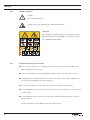
1245
1246
INSTRUCTION MANUAL
This instruction manual applies to machines
from the following serial numbers onwards:
# 6 500 124
296-12-19 199/002
Betriebsanleitung engl. 05.12
This Instruction Manual is valid for all models and subclasses listed in the
chapter "Specifications".
The adjustment manual for the machines can be downloaded free of
charge from the internet address
www.pfaff-industrial.com/pfaff/de/service/downloads
As an alternative to the internet download the adjustment manual can also be
ordered in book form under part no. 296-12-19 200/002.
The reprinting, copying or translation of PFAFF Instruction Manuals, whether in whole or
in part, is only permitted with our previous authorization and with written reference to the
source.
PFAFF Industriesysteme
und Maschinen AG
Hans-Geiger-Str. 12 - IG Nord
D-67661 Kaiserslautern
Index
Contents ..................................................................................Page
1
1.01
1.02
1.03
1.04
1.05
1.05.01
1.05.02
1.06
Safety .................................................................................................................................... 5
Directives ............................................................................................................................... 5
General notes on safety ......................................................................................................... 5
Safety symbols ...................................................................................................................... 6
Important points for the user ................................................................................................. 6
Operating and specialist personnel ........................................................................................ 7
Operating personnel .............................................................................................................. 7
Specialist personnel ............................................................................................................... 7
Danger warnings .................................................................................................................... 8
2
Proper use............................................................................................................................. 9
3
3.01
3.03
3.04
Specifications ..................................................................................................................... 10
4
Disposal of Machine .......................................................................................................... 12
5
5.01
5.02
5.03
5.04
Transportation, packing and storage ................................................................................ 13
Storage ................................................................................................................................ 13
6
Explanation of symbols ..................................................................................................... 14
7
7.01
7.02
7.03
7.04
7.05
Controls .............................................................................................................................. 15
8
8.01
8.01.01
8.01.02
8.01.03
8.01.04
8.01.05
PFAFF 1245, PFAFF 1246 ..................................................................................................... 10
Max. number of stitches/min-1 for the PFAFF 1245 ............................................................ 11
Max. number of stitches/min-1 for the PFAFF 1246 ............................................................ 11
Transportation to customer‘s premises ............................................................................... 13
Transportation inside the customer‘s premises ................................................................... 13
Disposal of packing materials .............................................................................................. 13
On/off switch ....................................................................................................................... 15
Pedals .................................................................................................................................. 15
Lever for lifting the presser foot .......................................................................................... 16
Feed regulator / reverse sewing ......................................................................................... 16
Adjustment nut for the top-feed stroke ............................................................................... 17
Installation and commissioning ....................................................................................... 18
Installation............................................................................................................................ 18
Adjusting the table-top height .............................................................................................. 18
Table top cutout ................................................................................................................... 19
Mounting the table top ........................................................................................................ 20
Mounting the upper V-belt guard ......................................................................................... 21
Mounting the bottom V-belt guard ....................................................................................... 21
3
Index
Contents ..................................................................................Page
8.01.06
8.01.07
8.02
8.03
8.04
9
9.01
9.02
9.03
9.04
9.05
9.06
10
10.01
10.02
10.03
10.04
10.05
10.06
11
4
Fitting the tilt lock................................................................................................................. 22
Fitting the reel stand ............................................................................................................ 22
Connecting the plug-in connections and earth cables ......................................................... 23
Commissioning .................................................................................................................... 24
Switching the machine on/off .............................................................................................. 24
Setting up ........................................................................................................................... 25
Inserting the needle ............................................................................................................ 25
Winding the bobbin thread, regulating the winder tension.................................................. 26
Removing/Threading the bobbin case .................................................................................. 27
Threading the bobbin thread and regulating the bobbin thread tension .............................. 27
Threading needle thread/adjusting needle thread tension on the PFAFF 1245 .............................28
Threading needle thread/adjusting needle thread tension on the PFAFF 1246 .............................29
Care and maintenance ....................................................................................................... 30
Servicing and maintenance intervals ................................................................................... 30
Cleaning ............................................................................................................................... 30
General lubrication ............................................................................................................... 31
Lubricating the hook ............................................................................................................ 32
Lubricating the head ............................................................................................................ 32
Lubricating the top-feed drive excentric............................................................................... 33
Wearing parts ..................................................................................................................... 34
Safety
1
Safety
1.01
Directives
This machine is constructed in accordance with the European regulations contained in the
conformity and manufacturer’s declarations.
In addition to this Instruction Manual, also observe all generally accepted, statutory and
other regulations and legal requirements and all valid environmental protection regulations!
The regionally valid regulations of the social insurance society for occupational accidents or
other supervisory organizations are to be strictly adhered to!
1.02
General notes on safety
● This machine may only be operated by adequately trained operators and only after having
completely read and understood the Instruction Manual!
● All Notes on Safety and Instruction Manuals of the motor manufacturer are to be read before operating the machine!
● The danger and safety instructions on the machine itself are to be followed!
● This machine may only be used for the purpose for which it is intended and may not be
operated without its safety devices. All safety regulations relevant to its operation are to
be adhered to.
● When exchanging sewing tools (e.g. needle, roller presser, needle plate and bobbin),
when threading the machine, when leaving the machine unattended and during maintenance work, the machine is to be separated from the power supply by switching off the
On/Off switch or by removing the plug from the mains!
● Everyday maintenance work is only to be carried out by appropriately trained personnel!
● Repairs and special maintenance work may only be carried out by qualified service staff
or appropriately trained personnel!
● Work on electrical equipment may only be carried out by appropriately trained personnel!
● Work is not permitted on parts and equipment which are connected to the power supply!
The only exceptions to this rule are found in the regulations EN 50110.
● Modifications and alterations to the machine may only be carried out under observance
of all the relevant safety regulations!
● Only spare parts which have been approved by us are to be used for repairs! We expressly point out that any replacement parts or accessories which are not supplied by us have
not been tested and approved by us. The installation and/or use of any such products can
lead to negative changes in the structural characteristics of the machine. We are not liable
for any damage which may be caused by non-original parts.
5
Safety
1.03
Safety symbols
Danger!
Points to be observed..
Danger of injury for operating and specialist personnel!
Caution
Do not operate without finger guard and safety devices.
Before threading, changing bobbin and needle, cleaning
etc. switch off main switch.
I
1.04
Important points for the user
● This Instruction Manual is an integral part of the machine and must be available to the
operating personnel at all times.
● The Instruction Manual must be read before operating the machine for the first time.
● The operating and specialist personnel is to be instructed as to the safety equipment of
the machine and regarding safe work methods.
● It is the duty of the user to only operate the machine in perfect running order.
● It is the obligation of the user to ensure that none of the safety mechanisms are removed
or deactivated.
● It is the obligation of the user to ensure that only authorized persons operate and work
on the machine.
Further information can be obtained from your PFAFF agent.
6
Safety
1.05
Operating and specialist personnel
1.05.01
Operating personnel
Operating personnel are persons responsible for the equipping, operating and cleaning of
the machine as well as for taking care of problems arising in the sewing area.
The operating personnel is required to observe the following points and must:
● always observe the Notes on Safety in the Instruction Manual!
● never use any working methods which could adversely affect the safety of the machine!
● not wear loose-fitting clothing or jewelery such as chains or rings!
● also ensure that only authorized persons have access to the potentially dangerous area
around the machine!
● always immediately report to the person responsible any changes in the machine which
may limit its safety!
1.05.02
Specialist personnel
Specialist personnel are persons with a specialist education in the fields of electrics, electronics and mechanics. They are responsible for the lubrication, maintenance, repair and adjustment of the machine.
The specialist personnel is obliged to observe the following points and must:
● always observe the Notes on Safety in the Instruction Manual!
● switch off the On/Off switch before carrying out adjustments or repairs, and ensure that
it cannot be switched on again unintentionally!
● wait until the luminous diode on the control box is no longer blinking or on before beginning adjustment or repair work.
● never work on parts which are still connected to the power supply! Exceptions are explained in the regulations EN 50110.
● replace the protective coverings and close the electrical control box afer all repairs or
maintenance work!
7
Safety
1.06
Danger warnings
A working area of 1 m must be kept free both in front of and behind the machine, so that easy access is possible at all times.
Never put your hands or fingers in the sewing area during sewing!
Danger of injury by the needle!
While setting or adjusting the machine do not leave any objects on the table nor
in the needle plate area! Objects may be trapped or flung out of the machine!
4
5
3
7
Fig. 1 - 01
1
2
Only operate the machine with covers 1 and 2 closed!
Danger of injury from the rotating hook!
Do not run the machine without finger guard 3!
Danger of injury by up and down movement of needle!
Do not run the machine without take-up lever guard 4!
Danger of injury by moving take-up lever!
Do not run the machine without belt guards 5 and 6!
Danger of injury by rotating v-belt!
Do not operate the machine without tilt lock 7!
Danger of crushing between sewing head and table!
8
6
Proper use
2
Proper use
PFAFF 1245
The PFAFF 1245 is a single needle, flatbed sewing machine with bottom, top and needle
feeds as well as a large vertical hook for sewing lockstitch seams. The machine is designed
for commercial use (industry).
PFAFF 1246
The Pfaff 1246 is a two-needle, flat bed sewing machine with bottom, top and needle feed
as well as vertical sewing hook for lockstitch seams. The machine is intended for commercial
(industrial) use only.
Any and all uses of this machine which have not been approved of by the
manufacturer are considered to be inappropriate! The manufacturer cannot be
held liable for any damage caused by the inappropriate use of the machine!
The appropriate use of the machine includes the observance of all operational,
adjustment, maintenance and repair measures required by the manufacturer!
9
Specifications
3
Specifications
3.01
PFAFF 1245, PFAFF 1246 ◆
Stitch type: .........................................................................................................301 (lockstitch))
Needle system: ............................................................................................................. 134 - 35
Needle sizes in 1/100 mm:
Version CN: .................................................................................................................. 110 - 140
Version CN: ................................................................ For processing medium-heavy materials
Max. thread size max. ( Synthetiks ):
Version CN: ......................................................................................................................... 20/3
Max. stitch length:
Version CN: ....................................................................................................................6,0 mm
Version CN 8: .................................................................................................................8,0 mm
Handwheel eff. dia.: .......................................................................................................80 mm
Dimensions of machine:
Length 1245 / 1246: ............................................................................... approx. 530 / 570 mm
Width: ............................................................................................................. approx. 177 mm
Height: ............................................................................................................ approx. 410 mm
Clearance width: ..........................................................................................................265 mm
Clearance height: ......................................................................................................... 115 mm
Fabric clearance (presser foot raised): ...........................................................................14 mm
Net weight (machine head): .................................................................................approx. 40 kg
Motor data: ................................................................................. see motor specification plate
Noise data:
Emission sound level at the workplace at appropriate speed
(Noise measurement in accordance with DIN 45 635-48-A-1, ISO 11204, ISO 3744, ISO 4871)
PFAFF 1245 at a speed of 2300 spm.: ...............................................................LpA = 82 dB(A)
PFAFF 1246 at a speed of 2200 spm.: ...............................................................LpA = 82 dB(A)
◆
▲
■
10
Subject to alterations
synthetic, or other sizes of comparable thread types
KpA = 2,5 dB
Specifications
3.03
3.04
Max. number of stitches/min-1 for the PFAFF 1245
Top feed lift
Max. number of
stitches/min-1 for
stitch lengths up to 6 mm
Max. number of
stitches/min-1 for stitch
lengths from 6 mm to 8 mm
less than 3,5 mm
2800
2600
from 3,5 to 5,5 mm
2500
2500
from 5,5 to 7,0 mm
2000
2000
Max. number of stitches/min-1 for the PFAFF 1246
Top feed lift
Max. number of
stitches/min-1
for stitch lengths
up to 6 mm and
needle gauge of up
to 10 mm
Max. number of
stitches/min-1
for stitch lengths
up to 6 mm and
needle gauge of
more than 10 mm
Max. number of
stitches/min-1
for stitch lengths
from 6 mm to
8 mm and
needle gauge of
up to 10 mm
Max. number of
stitches/min-1
for stitch lengths
up to 6 mm to
8 mm and
needle gauge of
more than
10 mm
less than
3,5 mm
2700
2500
2500
2300
from 3,5
to
5,5 mm
2400
2200
2400
2100
from 5,5
to
7,0 mm
1900
1700
1900
1600
11
Disposal of Machine
4
Disposal of Machine
● Proper disposal of the machine is the responsibility of the customer.
● The materials used for the machine are steel, aluminium, brass and various plastic
materials. The electrical equipment comprises plastic materials and copper.
● The machine is to be disposed of according to the locally valid pollution control regula-tions; if necessary, a specialist ist to be commissioned.
Care must be taken that parts soiled with lubricants are disposed of separately
according to the locally valid pollution control regulations!
12
Transportation, packing and storage
5
Transportation, packing and storage
5.01
Transportation to customer‘s premises
The machines are delivered completely packed.
5.02
Transportation inside the customer‘s premises
The manufacturer cannot be made liable for transportation inside the customer‘s premises
nor to other operating locations. It must be ensured that the machines are only transported
in an upright position.
5.03
Disposal of packing materials
The packing materials of this machine comprise paper, cardboard and VCE fibre. Proper disposal of the packing material is the responsibility of the customer.
5.04
Storage
If the machine is not in use, it can be stored as it is for a period of up to six months, but It
should be protected against dust and moisture.
If the machine is stored for longer periods, the individual parts, especially the surfaces of
moving parts, must be protected against corrosion, e.g. by a film of oil.
13
Explanation of symbols
6
Explanation of symbols
In this instruction manual, work to be carried out or important information is accentuated by
symbols. These symbols have the following meanings:
Note, information
Cleaning, care
Lubrication
Maintenance, repairs, adjustment, service work
(only to be carried out by technical staff)
14
Controls
7
Controls
7.01
On/off switch
● The power supply to the machine is switched on or off by turning switch 1.
The illustrated on/off switch is
fitted to machines with Quick
motors. If other motors are
used, a different switch may be
fitted.
1
Fig. 7 - 01
7.02
Pedals
● With the on/off switch on
0
= Machine stop
+1 = Sew
+2 = Raise presserfoot
+2
0
+1
Fig. 7 - 02
15
Controls
7.03
Lever for lifting the presser foot
● The sewing foot can be lifted by raising
lever 1.
1
Fig. 7 - 03
7.04
Feed regulator / reverse sewing
● Adjust the stitch length by turning the
knurled nut 1 accordingly.
Reverse sewing
● Press knurled nut 1 upwards as far as
possible (position "R"
1
Fig. 7 - 04
16
Controls
7.05
Adjustment nut for the top-feed stroke
Switch the machine off!
Danger due to unintentional
starting of the machine!
1
● Open cover 1 on the back of the machine, loosen screw 2 and move as required.
2
Fig. 7 - 05
17
Installation and commissioning
8
Installation and commissioning
The machine must only be mounted and commissioned by qualified personnel!
All relevant safety regulations are to be observed!
If the machine is delivered without a table, it must be ensured that the frame
and the table top which you intend to use can hold the weight of the machine
and the motor. It must be ensured that the supporting structure is sufficiently
sturdy, including during all sewing operations.
8.01
Installation
The site where the machine is installed must be provided with suitable connections for the
electric current, see Chapter 3 Specifications.
It must also be ensured that the standing surface of the machine site is firm and horizontal,
and that sufficient lighting is provided.
The method of packaging used requires that the table top be lowered for transport. The following is a description of how to adjust the height of the table top.
8.01.01
Adjusting the table-top height
1
1
2
Fig. 8 - 01
● Loosen screws 1 and 2 and set the desired table-top height
● Tighten screws 1 well.
● Adjust the position of the pedal so that you can operate it comfortably and tighten screw 2.
18
Installation and commissioning
8.01.02
Table top cutout
PFAFF 1245
PFAFF 1246
19
View:
Underside table top
120
102,5
PFAFF 1246
PFAFF 1245
= Main switch
= Drillhole for sewing head support
= Drillhole for reel stand
= Stand position
102,5
186
100
70 ± 0,5 65
14
= Drillholes for fastening the motor
= Braeket for drawer
= Drillhole for Synchronizer
9
120
100
20
50
35
70
150
73
17
22
170
28
35
75
8.01.03
50
28
35
1060
Installation and commissioning
Mounting the table top (on machines with drive MJ-0-00-215-CE)
500
Installation and commissioning
8.01.04
Mounting the upper V-belt guard
If a large balance wheel is
used, the corner 1 of the belt
guard 2 must be broken out.
1
● Attach belt guard section 2.
● Attach belt guard section 3.
2
3
Fig. 8 - 04
8.01.05
Mounting the bottom V-belt guard
● Adjust bottom -V-belt guard 1 so that the
motor pulley and V-belt run freely.
Please note the instructions
in the operating manual of
the drive.
1
Fig. 8 - 05
21
Installation and commissioning
8.01.06
Fitting the tilt lock
Switch off the machine!
Danger of injury due to unintentional starting of the machine!
● Screw on tilt lock 1, provided in the accessories, using screw 2.
Do not operate the machine
without tilt lock 1!
Danger of crushing between
2
sewing head and table top!.
teil und Tischplatte!
1
Fig. 8 -06
8.01.07
Fitting the reel stand
● Fit the reel stand as shown in Fig. 8 - 07.
● Afterwards insert the stand in the hole in
the table top and secure it with nuts provided.
Fig. 8 - 07
22
Installation and commissioning
8.02
Connecting the plug-in connections and earth cables
1
Fig. 8 - 08
● Connect all plug connections as described in the operations manual of the drive
● The following ground cables must be attached in order to discharge static electricity.
● Attach ground cables for machine, main switch, control unit and motor to ground point 1.
23
Installation and commissioning
8.03
Commissioning
1
● Check the machine, particularly its
electrical wiring for any damage.
● Remove pin 1 of the oil reservoir 2
(Fig. 8 - 09). The pin serves only to
protect the machine from damage during
transport and must not be used when
sewing.
● Clean the machine thoroughly and oil it
(see chapter 10 Care and maintenance).
● Have skilled personnel check if the machine can be operated with the available
mains voltage.
2
Fig. 8 - 09
8.04
Switching the machine on/off
● Switch the machine on (see Chapter 7.01, On/off switch).
24
Do not operate the machine if
there is any discrepancy.
The machine may only be connected to an earthed socket!
Setting up
9
Setting up
All instructions and regulations in this instruction manual must be observed.
Special attention must be given to all safety regulations!
All setting-up work must only be done by personnel with the necessary training. For all setting-up work the machine must be isolated from its power supply
by turning off the on/off switch or removing the machine plug from the electric
power socket!
9.01
Inserting the needle
1
2
1
2
Fig. 9 - 01
Fig. 9 - 01a
Switch the machine off!
Danger due to unintentional starting of the machine!
Only use needles from the system intended for the machine, see Chapter 3
Specifications.
PFAFF 1245
● Set needle bar at top position and
loosen screw 1.
PFAFF 1246
● Set needle bar at top position and loosen
screws 1.
● Insert the needle as far as possible
(the long needle-groove must be
facing left).
● Push needles 2 fully in (the long groove
of the left needle must face to the right
and that of the right needle to the left).
● Tighten needle retaining screw 1.
● Tighten screws 1 again.
25
Setting up
9.02
Winding the bobbin thread, regulating the winder tension
4
6
1
3
2
5
Fig. 9 -02
● Place an empty bobbin 1 on winder spindle 1.
● Thread up as shown in Fig. 9-02 and wind the thread a few ttimes clockwise around
bobbin 1. Engage the bobbin winder by pressing spindle 2 and lever 3 simultaneously
The bobbin is wound during sewing.
● The tension of the thread wound onto bobbin 1 is set on knurled screw 4.
● The bobbin winder will stop when sufficient thread is wound onto bobbin 1.
If the thread is wound on unevenly:
● Loosen nut 5.
● Turn thread guide 6 as required.
● Tighten nut 5 again.
26
Setting up
9.03
Removing/Threading the bobbin case
Switch the machine off!
Danger due to unintentional
starting of the machine!
1
Removing the bobbin case:
● Open the bed slide.
● Raise latch 1 and remove bobbin
case 2.
Inserting the bobbin case.
● Insert bobbin case 2 so that it clicks into
place.
● Close latch 1 and close the bed slide.
2
Fig. 9 -03
Do not operate the machine when the hook compartment cover is open!
Danger of injury from moving parts!
9.04
Threading the bobbin thread and regulating the bobbin thread tension
Switch the machine off!
Danger due to unintentional
starting of the machine!
● Thread the bobbin as shown in Fig. 9-04.
● When the thread is pulled, the bobbin
must rotate as shown by the arrow.
● Regulate the bobbin thread tension on
srew 1.
Fig. 9 - 04
27
Setting up
9.05
Threading needle thread/adjusting needle thread tension on the PFAFF 1245
1
Fig. 9 - 05
Switch the machine off!
Danger due to unintentional starting of the machine!
● Thread the machine as shown in Fig. 9 - 05. Take note that the needle is threaded from
the left (see arrow).
● Adjust the needle thread tension by turning knuled screw 1.
28
Setting up
9.06
Threading needle thread/adjusting needle thread tension on the PFAFF 1246
2
1
Fig. 9 - 06
Switch the machine off!
Danger due to unintentional starting of the machine!
● Thread the machine as shown in Fig. 9 - 06. Care must be taken that the left-hand needle
is threaded from the right and the right-hand needle is threaded from the left.
● Adjust the needle thread tension by turning knurled screws 1.
29
Care and maintenance
10
Care and maintenance
10.01
Servicing and maintenance intervals
Clean the hook compartment ........................... daily, more often if in continuous operation
Check the hook oil-container .............................................................................once a week
Clean the hook ..................................................................................................once a week
General lubrication .......................................................................................... twice a week
Lubricate the front parts ................................................................................. twice a week
Lubricate the top-feed drive eccentric .................................................................... Annually
These maintenance intervals are calculated for the average running time of a
single shift operation. If the machine is operated more than this, shorter intervals are recommended.
10.02
Cleaning
Switch off the machine!
Danger of injury due to unintentional starting of the machine!
3
2
● Clean hook area with a brush daily, in
continuous operation several times daily.
● Clean the hook thoroughly once a week.
● Open post cover.
● Set needle bar at its highest position.
● Remove top of bobbin case together
with bobbin
● Unscrew and remove hook gib 1.
1
Fig. 10 - 02
● Turn balance wheel until point of bobbin
case 2 has entered into the groove of the
hook race by about 5 mm.
● In this position remove bobbin case 2.
● Clean hook race with petroleum spirit.
● When inserting the bobbin case, make sure that bobbin case position finger 3 enters the
slot in the needle plate.
● Screw on hook gib 1.
● Insert bobbin case and close post cover.
30
Care and maintenance
10.03
General lubrication
1
Fig. 10 - 03
Switch off the machine!
Danger of injury due to unintentional starting of the machine!
Only use oil with a medium viscosity of 22.0 mm²/s at 40° C and a density of
0.865 g/cm³ at 15°C!
● Lubricate all bearings marked in Fig. 10.03 twice a week (see arrows).
Open the bed slide to gain access to oiling point 1.
● Tilt the machine backwards.
● Lubricate all bearings marked in Fig. 10.03 twice a week (see arrows).
Set the machine upright with both hands!
Danger of crushing between sewing head and table!
We recommend PFAFF sewing-machine oil, part No. 280-1-120 144.
31
Care and maintenance
10.04
Lubricating the hook
2
Switch off the machine!
Danger of injury due to unintentional starting of the machine!
● Tilt the machine backwards.
● Fill oil reservoir 1 through hole 2 up till
the topmost marking.
Only use oil with a medium viscosity of 22.0 mm²/s at 40° C
and a density of 0.865 g/cm³ at
15°C!
1
We recommend PFAFF
sewing-machine oil, part
No. 280-1-120 144.
Fig. 10 - 04
Use both hands to set the sewing head upright!
Danger of crushing between the sewing head and the table top!
10.05
Lubricating the head
Switch off the machine!
Danger of injury due to unintentional starting of the machine!
● Unscrew the face plate.
● Lubricate all bearings and moving parts
marked in Fig. 10 - 05 twice a week.
● Screw the face plate back on.
Only use oil with a medium viscosity of 22.0 mm²/s at 40° C
and a density of 0.865 g/cm³ at
15°C!
We recommend PFAFF
sewing-machine oil, part
No. 280-1-120 144.
Fig. 10 - 05
32
Care and maintenance
10.06
Lubricating the top-feed drive excentric
Switch off the machine!
Danger of injury due to unintentional starting of the machine!
1
● Open cover 1 on the back of the machine.
● Grease nipple 2 at least once a year (use grease gun).
● Screw cover 1 back on.
2
Only use lithium base grease
with a dripping point of 185°C
and a worked penetration of
22-25 mm at 25°C.
We recommend Pfaff
sewingmachine grease Part
no. 280-1-120 247.
Fig. 10 - 05
33
Wearing parts
11
Wearing parts
This is a list of the most important wearing parts.
A detailed parts list for the complete machine is included with the accessories.
In case of loss, the parts list can be downloaded from the internet address
www.pfaff-industrial.com/pfaff/de/service/downloads As an alternative to
the internet download the parts lists can also be ordered in book form under
part no. 296-12-19 199.
91-000 085-15
91-100 366-15
91-100 422-15 (2x)
91-000 407-15 (2x)
11-108 093-15
91-173 664-15 (2x)
11-174 089-15
91-141 980-91
91-141 981-91
System 134 - 35
91-018 339-05
34
Wearing parts
99-137 151-45
91-171 049-05
91-171 042-05
95-774 464-25
91-700 996-15
PFAFF 1245; 1246
91-010 937-05 (PFAFF 1245) C
91-015 519-05 (PFAFF 1246) C
35
Hans-Geiger-Str. 12 - IG Nord
D-67661 Kaiserslautern
Phone:
Fax:
E-mail:
+49 - 6301 3205 - 0
+49 - 6301 3205 1386
[email protected]
Hotlines:
Technical service:
Application consultance:
Spare-parts hotline:
Printed in Germany
+49 - 175/2243-101
+49 - 175/2243-102
+49 - 175/2243-103
© PFAFF Industriesysteme und Maschinen AG 2009, PFAFF is the exclusive trademark of VSM Group AB.PFAFF Industriesysteme und Maschinen AG is an authorized licensee of the PFAFF trademark.
PFAFF Industriesysteme
und Maschinen AG