1
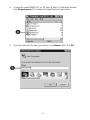
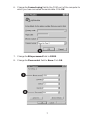
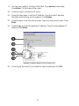
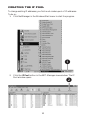
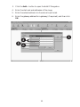
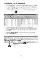
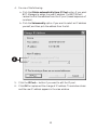
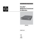
™
NET350
MULTIMEDIA TRANSMISSION VIA NETWORK
®
QUICK START
GUIDE
C2907M-QS (09/03)
BEFORE YOU BEGIN
Installation of PelcoNet NET350 requires support from your network
administrator. Contact your administrator to assist with STEP 2A –
Configuring PelcoNet Using HyperTerminal. Write down the following
information from your network administrator:
1.
A unique IP address for each NET350 unit
____.____.____.____.
2.
The subnet mask for each IP address
____.____.____.____.
3.
____.____.____.____.
____.____.____.____.
The default gateway for each address
____.____.____.____.
____.____.____.____.
2
STEP 1A
CONNECTING THE TRANSMITTER —
NET350T
1. Plug in the supplied power adapter to power-up the PelcoNet. Be sure
to use the correct power supply adapter (configure if needed).
2. Attach a camera to the Video In connector.
3. Connect a network cable to the Ethernet port.
4. (Optional) Connect the COM1: RS232/422/485 port with a serial cable
to any controllable devices (for example, Genex® multiplexer, System
9760®, Spectra® dome).
�
NET350 FRONT
Alarm I/O
Ethernet
Power
Compact Flash
I
O
L
T
�
�
NET350 BACK
75
Audio I/O
Video In
COM2:
RS232
COM1:
RS232/422/485
Power
RX+ RX-
RECEIVER OR SPECTRA
TX+
TX4800, 8, NONE, 1
3
�
STEP 1B
CONNECTING THE RECEIVER —
NET350R
NOTE: Skip this step if a receiver will not be used.
1. Plug in the supplied power adapter to power-up the PelcoNet. Be sure
to use the correct power supply adapter (configure if needed).
2. Attach a monitor to the Video Out connector.
3. Connect a network cable to the Ethernet port.
4. (Optional) Connect the COM1: RS232/422/485 port with a serial cable
to a keyboard (for example, KBD4000, CM9760-KBD, KBD300A).
�
NET350 FRONT
Alarm I/O
I
Ethernet
O
L
Power
T
�
�
NET350 BACK
KBD300A
75
Audio I/O
Video Out
COM2:
RS232
COM1:
RS232/422/485
12 VAC
Power
RX-
4
3
2
1
5
6
7
8
DIRECT
MODE
RX+
MONITOR
4800, 8, NONE, 1
STRAIGHT
CABLE
4
�
STEP 2A
CONFIGURING THE NET350 USING
HYPERTERMINAL
NOTE: If you do not want to configure PelcoNet using HyperTerminal or NETManager, refer to the PelcoNet NET350 manual for instructions on configuring
PelcoNet using a web browser.
1. Connect a null modem RS232 serial cable from your computer’s COM
port to the COM2: RS232 port on the NET350’s back panel.
�
75
Audio I/O
Video In
COM2:
RS232
COM1:
RS232/422/485
Power
2. Click the Start button on the desktop, and then select Programs from
the Start menu.
3. Highlight Accessories. Highlight Communications. Click
HyperTerminal.
�
�
5
4. If using Windows® 2000, NT, or XP, skip to Step 5. Otherwise, doubleclick Hypertrm.exe. This opens the HyperTerminal application.
�
5. Type the name for the new connection in the Name field. Click OK.
�
6
6. Change the Connect using field to the COM port of the computer to
which you have connected the serial cable. Click OK.
�
7. Change the Bits per second field to 19200.
8. Change the Flow control field to None. Click OK.
�
�
7
9. You are now ready to configure PelcoNet. Type service (lowercase).
Press Enter. This brings up the menu.
10. Press the i key to access the IP menu.
11. Press the i key again to set the IP address. Type the new IP address
PelcoNet will be using on the network. Press Enter.
12. Press the s key to set the subnet mask. Type the new subnet mask. Press
Enter.
13. Press the g key to set the gateway IP address. Type the new gateway IP
address. Press Enter.
�
��
��
��
��
14. Close HyperTerminal. If prompted to save the settings, click OK.
8
STEP 2B
CONFIGURING THE NET350 USING
NET-MANAGER
NOTE: If you do not want to configure PelcoNet using HyperTerminal or NETManager, refer to the PelcoNet NET350 manual (C2907M) for instructions on
configuring PelcoNet using a web browser.
INSTALLING NET-MANAGER
1. Insert the PelcoNet Resource CD in your PC’s CD drive. The PelcoNet
Installation and User Guide appears after a short interval.
2. Click NET350. A list of programs you can install is displayed.
3. Click Install Net-Manager. The NET-Manager Setup Welcome screen
appears.
4. Follow the on-screen installation instructions.
5. Click Finish when you are prompted to complete the installation.
NET-Manager is now installed.
6. Click Back and then click Exit to leave the installation program.
Remove the CD.
9
CREATING THE IP POOL
To change existing IP addresses, you first must create a pool of IP addresses.
To do so:
1. Click NetManager in the Windows Start menu to start the program.
�
2. Click the IP Pool button in the NET-Manager view window. The IP
Pool window opens.
�
10
3. Click the Add… button to open the Add IP Range box.
4. Enter the start and end addresses of the range.
5. Enter the subset address into the subnet input mask.
6. Enter the gateway address for a gateway (if required), and then click
OK.
�
�
�
�
11
CHANGING THE IP ADDRESS
1. Click the List button. A list of found PelcoNet units will be displayed
in the NET-Manager view window. (If NET-Manager is not already
started, click NetManager in the Windows Start menu and then click
the Start scanning… button in the dialog box to search the network.)
�
2. Move the mouse pointer onto the desired server, and then click the
right mouse button. You are now ready to configure PelcoNet. (Note:
an IP address must have been defined in an IP pool before it can be
changed.)
3. Select Change IP address… in the context menu. The Change IP
Address window opens.
�
�
12
4. Do one of the following:
a. Click the Obtain automatically from IP Pool option if you want
NET-Manager to assign the new IP address. The NET350 will
receive the first free address from the IP pool (lowest sequence of
numbers).
b. Click the Set manually option if you want to select an IP address
yourself, and then pick the address from the list.
�
5. Click the IP Pool… button if you want to edit the IP pool.
6. Click OK to implement the change of IP address. The window closes
and the new IP address appears in the view window.
13
STEP 3
FINAL CONNECTION SETTINGS
If you changed the transmitter and receiver IP addresses in STEP 2, then use the
new addresses to connect to the units. Also use the new addresses to make
changes to any settings. If no changes were made to the IP addresses in STEP 2,
use the default address for the transmitter (10.0.0.1) and the default address for
the receiver (10.0.0.2).
1. Install Internet Explorer 6.0 (if you have not already done so) from the
CD supplied with PelcoNet NET350 on to a computer connected to
the network.
2. Open Internet Explorer 6.0.
3. Type the receiver’s IP address in the address field, and then press Enter
to connect to the receiver.
4. Click the Setup icon.
5. Click Alarm Settings to bring up the Alarm Settings page.
�
�
14
6. Type the transmitter’s IP address in the Live video receiver IP address
box. Click Set.
7. Set Live video auto-connect to On. Click Set.
�
�
8. Installation is now complete. (Note, however, that you must install the
ActiveX® platform in order to view live video on the browser. Refer to
the NET350 manual for instructions.)
15
®
3500 Pelco Way • Clovis, CA 93612-5699 USA
North America and Canada
Tel (800) 289-9100 • FAX (800) 289-9150
International
Tel +1(559) 292-1981 • FAX +1(559) 348-1120
www.pelco.com
® Pelco, the Pelco logo, Spectra, Genex and System 9760 are registered trademarks of Pelco.
® Windows and ActiveX are registered trademarks of Microsoft Corporation.
™PelcoNet is a trademark of Pelco.
© Copyright 2003, Pelco. All rights reserved.