1
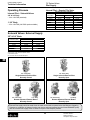
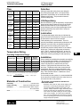
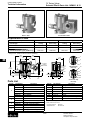
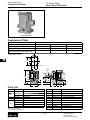
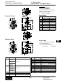
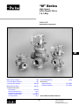
“N” Series High Speed Inline Poppet Valves 2 & 3-Way Section M www.parker.com/pneu/n M Basic Valve Functions............................................... M2 Time Delay Modules................................................ M16 “N” Series Basic Features......................................... M3 Dimensions Single Solenoid........................................... M17-M20 Remote Operated........................................ M21-M22 Common Part Numbers....................................... M4-M5 Model Number Index........................................... M6-M7 Technical Information Pilot Supply..................................................... M8-M9 Electrical Connections........................................ M10 Solenoid Characteristics..................................... M11 Solenoid & Parts Lists................................. M12-M14 Coil Information................................................... M15 BOLD ITEMS ARE MOST POPULAR. M1 Parker Hannifin Corporation Pneumatic Division Richland, Michigan www.parker.com/pneumatics Catalog 0600P-10/USA “N” Series Valves Inline Poppet Valve Basic Valve Functions Single Solenoid 3-Way, 2-Position NC (NNP) M Single Solenoid 3-Way, 2-Position NO (NP) CYL EXH IN CYL EXH IN Normal position – Pressure at inlet port marked “IN” blocked. Cylinder port connected to exhaust port (3-Way). Normal position – Pressure at inlet port marked “IN” open to cylinder. Exhaust port is blocked (3-Way). Energized position – Solenoid operator energized, pressurized “IN” port connects to cylinder port. Exhaust port is blocked (3-Way). Energized position – Solenoid operator energized. Pressure at inlet port marked "IN" is blocked. Cylinder open to exhaust (3-Way). ! ! CAUTION: These are poppet valves, Do Not restrict the inlet. CAUTION: These are poppet valves, Do Not restrict the inlet. Note: For 2-Way, Normally Closed, Exhaust Port is Plugged. Note: For 2-Way, Normally Open, Exhaust Port is Plugged. Single Remote Pilot 3-Way, 2-Position, NC (NNP) Single Remote Pilot 3-Way, 2-Position, NO (NP) CYL Remote Signal EXH IN CYL Remote Signal EXH IN Normal position – Pressure at inlet port marked “IN” blocked. Cylinder port connected to exhaust port (3-Way). Normal position – Pressure at inlet port marked “IN” open to cylinder. Exhaust port is blocked (3-Way). Operated position – With maintained air signal at pilot port, pressurized “IN” port connects to cylinder port. Exhaust port is blocked (3-Way). Operated position – With maintained air signal at pilot port, pressure at inlet port marked "IN" is blocked. Cylinder open to exhaust (3-Way). ! ! CAUTION: These are poppet valves, Do Not restrict the inlet. CAUTION: These are poppet valves, Do Not restrict the inlet. Note: For 2-Way, Normally Closed, Exhaust Port is Plugged. Note: For 2-Way, Normally Open, Exhaust Port is Plugged. For Information on Options that are no longer available and the Suggested Cross Reference or Kit Info, refer to www.parker.com/pneumatic/classicvalves & Catalog N Series-E/USA M2 Parker Hannifin Corporation Pneumatic Division Richland, Michigan www.parker.com/pneumatics Catalog 0600P-10/USA “N” Series Valves Inline Poppet Valve Basic Features “N” Series Specifications • 2-Way NC • 3-Way NO & NC • Selector Function Flow • 3/8" Body – 3.0 to 4.4 Cv • 3/4" Body – 9.0 to 11.0 Cv • 1-1/4" Body – 20.0 to 30.0 Cv Port Sizes • 3/8" Body – 3/8", 1/2" NPT • 3/4" Body – 1/2", 3/4", 1" NPT • 1-1/4" Body – 1", 1-1/4", 1-1/2" NPT • BSPP “G” Threads Available 3/8" Solenoid Pilot De-Energized Normally Closed M Operating Pressure • 30 to 250 PSI (0 to 1000 kPa) • Vacuum with External Pilot Features • Continuous Duty Rated Option • Non-Lube Service • Hi-Flow, Short Stroke Poppet • Indicator Lights Available Certification / Approval • Approved to be CE Marked (Standard L-Pilot & P-Pilot) • NEMA 4 Option • Hazardous Duty Option 1-1/4" Solenoid Pilot De-Energized Normally Open Pressure M3 Exhaust Parker Hannifin Corporation Pneumatic Division Richland, Michigan www.parker.com/pneumatics Catalog 0600P-10/USA Common Part Numbers “N” Series Valves Inline Poppet Valve – Solenoid Operated Single Solenoid Normally Closed Single Solenoid Normally Open 2-Way, 2-Position 3-Way, 2-Position 3-Way, 2-Position 3/8" & 3/4" Body Size 3/8" & 3/4" Body Size 2-Way 3-Way In/Cyl Normally Closed Normally Closed Ports 3/8" 3/4" Exh. Port 3/8" 3-Way Normally Open In/Cyl Ports Exh Port N375 39 045 53 3/8" 1/2" N375 49 045 53 1/2" 1/2" N375 59 045 53 1/2" 3/4" N315 39 045 53 N355 39 045 53 3/8" 1/2" N315 49 045 53 N355 49 045 53 1/2" 1/2" N315 59 045 53 N355 59 045 53 1/2" 3/4" N315 69 045 53 N355 69 045 53 3/4" 1" N375 69 045 53 3/4" 1" N315 79 045 53 N355 79 045 53 1" 1" N375 79 045 53 1" 1" 3/4" Locking Manual Override, Internal “P” Pilot 140 PSI, Standard Service, Junction Box w/ Light, 120VAC. Locking Manual Override, Internal “P” Pilot 140 PSI, Standard Service, Junction Box w/ Light, 120VAC. 1-1/4" Body Size 1-1/4" Body Size M 2-Way 3-Way In/Cyl Normally Closed Normally Closed Ports 1-1/4" Exh. Port 3-Way Normally Open 1-1/4" In/Cyl Ports Exh. Port N325 79 047 53 N365 79 047 53 1" 1-1/4" N385 79 047 53 1" 1-1/4" N325 89 047 53 N365 89 047 53 1-1/4" 1-1/2" N385 89 047 53 1-1/4" 1-1/2" N325 99 047 53 N365 99 047 53 1-1/2" 1-1/2" N385 99 047 53 1-1/2" 1-1/2" Locking Manual Override, Internal “P” Pilot 125 PSI, Standard Service, P-Pilot Junction Box w/ Light, 120VAC. Locking Manual Override, Internal “P” Pilot 125 PSI, Standard Service, P-Pilot Junction Box w/ Light, 120VAC. M4 Parker Hannifin Corporation Pneumatic Division Richland, Michigan www.parker.com/pneumatics Catalog 0600P-10/USA Common Part Numbers “N” Series Valves Inline Poppet Valve – Remote Pilot Operated Single Remote Pilot Normally Closed Single Remote Pilot Normally Open 2-Way, 2-Position 3-Way, 2-Position 3-Way, 2-Position 3/8" & 3/4" Body Size 3/8" & 3/4" Body Size 2-Way 3-Way In/Cyl Normally Closed Normally Closed Ports 3/8" 3/4" Exh. Port 3/8" 3-Way Normally Open In/Cyl Ports Exh. Port N374 31 091 3/8" 1/2" N374 41 091 1/2" 1/2" N374 51 091 1/2" 3/4" N314 31 091 N354 31 091 3/8" 1/2" N314 41 091 N354 41 091 1/2" 1/2" N314 51 091 N354 51 091 1/2" 3/4" N314 61 091 N354 61 091 3/4" 1" N374 61 091 3/4" 1" N314 71 091 N354 71 091 1" 1" N374 71 091 1" 1" 3/4" 1/4" NPT Remote Pilot Port with Internal Pilot Return. 1/4" NPT Remote Pilot Port with Internal Pilot Return. M 1-1/4" Body Size 1-1/4" Body Size 2-Way 3-Way In/Cyl Normally Closed Normally Closed Ports 1-1/4" Exh. Port 1-1/4" 3-Way Normally Open In/Cyl Ports Exh. Port N384 71 091 1" 1-1/4" N324 71 091 N364 71 091 N324 81 091 N364 81 091 1-1/4" 1-1/2" N384 81 091 1-1/4" 1-1/2" N324 91 091 N364 91 091 1-1/2" 1-1/2" N384 91 091 1-1/2" 1-1/2" 1" 1-1/4" 1/4" NPT Remote Pilot Port with Internal Pilot Return. 1/4" NPT Remote Pilot Port with Internal Pilot Return. M5 Parker Hannifin Corporation Pneumatic Division Richland, Michigan www.parker.com/pneumatics Catalog 0600P-10/USA “N” Series Valves Inline Poppet Valve – Solenoid Operated Model Number Index “N” Series 3/8", 3/4" & 1-1/4" Body Sizes - Solenoid ‘L’ Pilot N 315 3 9 0 45 53 — Valve Function - Solenoid Options 3/8" & 3/4" Body Blank 315 L 3-Way, Normally Closed 355 C Chrysler Wiring - Enclosure ‘J’ & ‘N’ 3-Way, Normally Open 375 F Ford Wiring - Enclosure ‘E’, ‘J’, & ‘N’ G GM wiring - Enclosure ‘J’ & ‘N’ 1-1/4" Body 2-Way, Normally Closed 325 3-Way, Normally Closed 365 3-Way, Normally Open 385 72" Leads - ‘51’ Voltage Code Only “L” Pilot Code Voltage Solenoid Enclosure Options Code AC AC DC 60hz 50hz Port Size / Thread Type 3/8" Body Size 3/8" Inlet & Cyl - 1/2" Exhaust - NPT 3 1/2" Inlet & Cyl - 1/2" Exhaust - NPT 4 1/2" Inlet & Cyl - 1/2" Exhaust - BSPP N 42 3/4" Body Size M None 2-Way, Normally Closed 1/2" Inlet & Cyl - 3/4" Exhaust - NPT 5 3/4" Inlet & Cyl - 1" Exhaust - NPT 6 3/4" Inlet & Cyl - 1" Exhaust - BSPP Q 1" Inlet & Cyl - 1" Exhaust - NPT 7 1-1/4" Body Size 1" Inlet & Cyl - 1 1/4"Exhaust - NPT 7 1-1/4" Inlet & Cyl – 1-1/2" Exhaust - NPT 8 1-1/4" Inlet & Cyl – 1-1/2" Exhaust - BSPP S* 1-1/2" Inlet & Cyl – 1-1/2" Exhaust - NPT 9 1-1/2" Inlet & Cyl – 1-1/2" Exhaust - BSPP T* 24 24 Standard Duty Cont. Duty 200 PSI (01, 45) (04, 48) (46) 6 5, 6 45 12 1, 5, 6 49 24 1, 2, 3, 5, 6, 8, 9, W 51 48 53 120 110 57 240 220 6 6, 8, 9 9 1 1, 2, 3, 5, 6, 8, 1, 6, 8, 9, N 9, E, N, W 8, 9, E 1, 3, W 61 120 5, 6 79 24 E, J E, J “L” Pilot Configuration 01* 04* * Not available with Valve Function 325. Note: BSPP is to the ISO 228 Standard, and requires an R-BSPT male fitting. External Pilot, Std Service, 140 PSI External Pilot, Cont Duty, 140 PSI 45 Internal Pilot, Std Service, 140 PSI 46 Internal Pilot, Std Service, 200 PSI 48 Internal Pilot, Cont Duty, 140 PSI * Not available with Valve Function 325, 365, and 385 (1-1/4" Body). Solenoid Enclosure Basic Pilot 1 Basic Pilot NLMO 2 Basic Pilot LMO 3 Junction Box NLMO 5 Junction Box LMO 6 Junction Box NLMO w/ Light 8 Junction Box LMO w/ Light 9 Basic Pilot Ext. LMO W JIC NLMO w/Light - 3-Pin Automotive E JIC NLMO w/ Light - 4-Pin M12 J JIC NLMO w/ Light - 5-Pin Automotive N Solenoid Type 0 Standard 5* Hazardous Duty 8* NEMA 4 Solenoid * Available with Solenoid Enclosure 2 & 3, ‘L’ Pilot Configuration 04 & 48, and Voltage 49 & 53 ONLY. BOLD OPTIONS ARE MOST POPULAR. M6 Parker Hannifin Corporation Pneumatic Division Richland, Michigan www.parker.com/pneumatics E, J Catalog 0600P-10/USA “N” Series Valves Solenoid & Remote Pilot Operated Valve Model Number Index “N” Series 1-1/4" Body Sizes - Solenoid Hi-Flow ‘P’ Pilot N 365 8 9 0 47 53 “P” Pilot Code Valve Function - Solenoid 1-1/4" Body 2-Way, Normally Closed 325 3-Way, Normally Closed 365 3-Way, Normally Open 385 Voltage Code AC AC DC 60hz 50hz 49 24 53 120 110 Enclosure Options Standard Duty 5, 6 5, 6, 8, 9 Port Size / Thread Type “P” Pilot Configuration 1-1/4" Body Size 1" Inlet & Cyl - 1 1/4"Exhaust - NPT 7 02 External Pilot, Std Service, 125 PSI 1-1/4" Inlet & Cyl – 1-1/2" Exhaust - NPT 8 47 Internal Pilot, Std Service, 125 PSI 1-1/4" Inlet & Cyl – 1-1/2" Exhaust - BSPP S 1-1/2" Inlet & Cyl – 1-1/2" Exhaust - NPT 9 1-1/2" Inlet & Cyl – 1-1/2" Exhaust - BSPP T Solenoid Type 0 Note: BSPP is to the ISO 228 Standard, and requires an R-BSPT male fitting. Standard Solenoid Enclosure Junction Box NLMO 5 Junction Box LMO 6 Junction Box NLMO w/ Light 8 Junction Box LMO w/ Light 9 M “N” Series 3/8", 3/4" & 1-1/4" Body Sizes - Remote Pilot N 314 3 1 91 Port Size / Thread Type Valve Function - Solenoid Pilot Configuration 3/8" Body Size 3/8" & 3/4" Body 2-Way, Normally Closed 314 3/8" Inlet & Cyl - 1/2" Exhaust - NPT 3 3-Way, Normally Closed 354 1/2" Inlet & Cyl - 1/2" Exhaust - NPT 4 3-Way, Normally Open 374 1/2" Inlet & Cyl - 1/2" Exhaust - BSPP N 2-Way, Normally Closed 324 1/2" Inlet & Cyl - 3/4" Exhaust - NPT 5 3-Way, Normally Closed 364 1/2" Inlet & Cyl - 3/4" Exhaust - BSPP P 3-Way, Normally Open 384 3/4" Inlet & Cyl - 1" Exhaust - NPT 6 3/4" Inlet & Cyl - 1" Exhaust - BSPP Q 1" Inlet & Cyl - 1" Exhaust - NPT 7 089 External Pilot Return 091 Internal Pilot Return 3/4" Body Size 1-1/4" Body 1-1/4" Body Size 1" Inlet & Cyl - 1 1/4"Exhaust - NPT 7 1-1/4" Inlet & Cyl – 1-1/2" Exhaust - NPT 8 1-1/4" Inlet & Cyl – 1-1/2" Exhaust - BSPP S* 1-1/2" Inlet & Cyl – 1-1/2" Exhaust - NPT 9 1-1/2" Inlet & Cyl – 1-1/2" Exhaust - BSPP T* * Not available with Valve Function 325. Note: BSPP is to the ISO 228 Standard, and requires an R-BSPT male fitting. BOLD OPTIONS ARE MOST POPULAR. M7 Parker Hannifin Corporation Pneumatic Division Richland, Michigan www.parker.com/pneumatics Catalog 0600P-10/USA Technical Information “N” Series Valves Pilot Supply Operating Pressure Internal Pilot – Remote Pilot Valve Internal Pilot – Solenoid Valves Air Pressure Thru Valve 25 PSI 50 PSI 75 PSI 100 PSI 150 PSI 200 PSI 250 PSI 3/8" & 3/4" Body • 20 to 140 PSIG (standard) 1-1/4" Body • 25 to 140 PSIG (200 PSIG option available) Operating Pressure Limitations Remote Pilot Pressure (PSI) 3/8" Basic 3/4" Basic 1-1/4" Basic 30-250 30-250 30-250 50-250 50-250 50-250 70-250 75-250 70-250 95-250 95-250 90-250 140-250 145-250 130-250 175-250 185-250 175-250 215-250 230-250 205-250 Solenoid Valves: External Supply 3/8" & 3/4" Basic Air Pressure Thru Valve (PSI) 25 PSI 50 PSI 75 PSI 100 PSI 150 PSI 250 PSI External Pilot Pressure Required (PSI)* 3/8" Basic 3/4" Basic 35-200 35-200 45-200 40-200 55-200 50-200 65-200 65-200 80-200 80-200 110-200 110-200 Vacuum up to 1" HG, less than a perfect vacuum. * With 200 PSI option. Do not exceed 140 PSI with standard pilots. M 3/8" & 3/4" Body 3/8" & 3/4" Body Single Solenoid External Pilot Normally Closed Single Solenoid External Pilot Normally Open 3/8" & 3/4" Body 1-1/4" Body 3/8" & 3/4" Body Remote Operated External Return Normally Closed 1-1/4" Body Remote Operated External Return Normally Open External Pilot supply should be used when the main valve needs to operate below the Minimum Operating Pressure or at Vacuum. A Selector function can also be achieved (pressurizing the IN and EXHAUST ports) with an External Pilot Supply. Refer to charts for required external pilot pressure. M8 Parker Hannifin Corporation Pneumatic Division Richland, Michigan www.parker.com/pneumatics Catalog 0600P-10/USA Technical Information “N” Series Valves Technical Data Flow Selection Although reasonable safety factors are designed into each speed poppet valve, it is important that application requirements do not exceed the rated limitation of the valve. This precaution insures a sufficient safety factor. Basic Valve Size Inlet Port Size Exhaust Port Size 3/8" 3-Way Normally Closed 3/8" Pipe 1/2" Pipe 3.6 4.2 1/2" Pipe 1/2" Pipe 3.8 4.3 3/8" 3-Way Normally Open 3/8" Pipe 1/2" Pipe 3.6 4.1 Life Expectancy 1/2" Pipe 1/2" Pipe 3.9 4.5 3/4" 3-Way Normally Closed 1/2" Pipe 3/4" Pipe 8.2 9.2 3/4" Pipe 1" Pipe 9.3 10.8 3/4" 3-Way Normally Open 1/2" Pipe 3/4" Pipe 7.7 6.6 Normal multimillion cycle life expectancy of high speed poppet series valves is based on the use of properly filtered and lubricated air at room temperature. In actual laboratory tests, the high speed poppet valves provide maintenance-free service life in excess of 20,000,000 cycles. 3/4" Pipe 1" Pipe 9.6 11.4 Lubrication 1-1/4" 3-Way Normally Closed 1" Pipe 1-1/4" Pipe 19.5 23.5 1-1/4" Pipe 1-1/2" Pipe 23.3 26.9 The high speed poppet valves are pre-lubricated to permit use with non-lubricated air. However, air should be lubricated to assure maximum seal life. 1-1/2" Pipe 1-1/2" Pipe 23.3 26.9 1" Pipe 1-1/4" Pipe 20.4 24.8 1-1/4" Pipe 1-1/2" Pipe 25.0 29.1 1-1/2" Pipe 1-1/2" Pipe 26.7 29.9 1-1/4" 3-Way Normally Open Cv Inlet Cv Cylinder to Cylinder to Exhaust F442 lubricating oil is recommended. This oil is specially formulated to provide peak performance and maximum service life from air-operated equipment. Other good air line lubricating oils may be used provided they atomize readily and are of the medium aniline type. Aniline point range must be between 180°F - 220°F. Viscosity SUS @ 100°F of 140-170. High aniline oils will shrink seals; low aniline oils will swell seals, reducing operating life and expectancy. Temperature Rating Operating Temperature Range: Operator Type Duty Cycle* Maximium Ambient Temperature Minimum Ambient Temperature Standard Service Intermittent 0°F (-18°C) 125°F (52°C) Solenoid Continuous 0°F (-18°C) 100°F (38°C) Special Service Intermittent 0°F (-18°C) 125°F (52°C) Continuous 0°F (-18°C) 125°F (52°C) Not Applicable 0°F (-18°C) 200°F (93°C Solenoid Remote Pilot Installation Valves should be installed with reasonable accessibility for service whenever possible. Care should be taken to hold piping length to a minimum and to protect valves from exposure to extreme heat, dirt and moisture. Piping should be clean and clear of dirt and chips. Threads should be the correct size and undamaged. Pipe joint compound should be used sparingly and only on pipe threads, never in the valve body. Care should be taken in installation to avoid undue strain on valve. * Applications with pilot valves energized for ten (10) minutes or longer with a duty cycle greater than 70% are considered to be continuously energized. Duty cycle = Time energized × 100% = % Duty Cycle Time energized + time off For the small port size options, it is recommended that an air reservoir is located close to the valve inlet as to not starve the valve of air pressure. Materials of Construction ! CAUTION: DO NOT RESTRICT THE INLET TO POPPET VALVES Restriction of the inlet can starve the air supply to the pilot section of internally piloted poppet valves and result in slow shifting or failure of the valve to shift properly. Always connect the supply line directly to the inlet of the valve using the full pipe size of the valve inlet. Never use a quick coupling to connect a poppet valve to the air supply. On valves with a small inlet port, use of an upstream surge tank may be required at lower operating pressures to insure an adequate air supply and proper operation. Valve Body......................................................Cast Aluminum Poppet Assembly.................... Aluminum and Stainless Steel Pilot Valve......................Zinc, Stainless Steel, Brass, Copper, Zinc Plated Steel Seals...............................................................................Nitrile M9 Parker Hannifin Corporation Pneumatic Division Richland, Michigan www.parker.com/pneumatics M Catalog 0600P-10/USA “N” Series Valves Electrical Connections Technical Information Automotive Connections • 3-Pin & 5-Pin “Mini” (7/8 UNF Thread) • 4-Pin “Micro” (M12 Thread) Solenoid Configurations “E”, “J”, “N” Wiring Connections Chrysler Connection 4-Pin Male/Single Solenoid 5-Pin Male/Single Solenoid (Encl. Option J, Wiring Option C) (Encl. Option N, Wiring Option C) 5-PIN MINI (TOP COVER) 4-PIN MICRO (TOP COVER) 1 5 2 4 (-) Common (-) Common (+) Signal (+) Signal GRN SOLENOID COIL NOT USED 3 NOT USED 3 NOT USED M 4 2 GRN SOLENOID COIL 1 Ford Connection 3-Pin Male/Single Solenoid 4-Pin Male/Single Solenoid 5-Pin Male/Single Solenoid (Encl. Option E, Wiring Option F) (Encl. Option J, Wiring Option F) (Encl. Option N, Wiring Option F) 4-PIN MICRO (TOP COVER) 3 1 5 2 4 3 SOLENOID COIL (+) Signal (-) Common (-) Common (-) Common (+) Signal (+) Signal NOT USED 4 2 GRN SOLENOID COIL 1 NOT USED NOT USED GRN SOLENOID COIL 3 NOT USED 1 2 5-PIN MINI (TOP COVER) GM Connection 4-Pin Male/Single Solenoid 5-Pin Male/Single Solenoid (Encl. Option J, Wiring Option G) (Encl. Option N, Wiring Option G) 5-PIN MINI (TOP COVER) 1 4 3 SOLENOID COIL (-) Common (-) Common (+) Signal (+) Signal M10 5 2 NOT USED 3 GRN 4 2 NOT USED SOLENOID COIL 1 NOT USED NOT USED 4-PIN MICRO (TOP COVER) Parker Hannifin Corporation Pneumatic Division Richland, Michigan www.parker.com/pneumatics Catalog 0600P-10/USA Technical Information “N” Series Valves Solenoid Characteristics Solenoid Characteristics Chart Continuous Duty Pilots Voltage Range +10/-15% of Nominal Continuous duty pilots are designed for applications where cycling is infrequent and the pilot is to be energized for indefinite periods of time . . . hours, days or weeks. Typical uses include fail-safe or emergency shutdown circuits where the pilot is to be energized and the valve open as long as the main control is “live” in order to shut off air to equipment in the event of power failure. The Continuous duty pilot operates satisfactorily in ambient temperatures up to 125°F, even when continuously energized and without the benefit of the cooling air which normally flows through the pilot during frequent cycling. Under certain conditions, satisfactory operation may be obtained at ambient temperatures above 125°F. CONSULT FACTORY. Incorporating the performance-proven design features of the standard L-Pilot, the continuous duty pilot utilizes a bullet-shaped stem on the upper end of the plunger. This bullet-shaped stem, seating in a high-temperature rubber o-ring, provides both a bubble-tight seal and Continuous Duty positive release. Pilot 3/8" & 3/4" Basic – L-Pilot Voltage/ Cycles Amps Inrush Amps Holding Resistance Ohms Watts Insulation Class 120/60VAC .29 .18 122 12 B 110/50VAC .21 .14 122 12 B 240/60VAC .18 .12 610 12 B 24/60VAC 1.6 1.0 4.5 9.5 B 24/50VAC 1.2 .75 6.4 9.5 B 6VDC – 1.4 4.5 7.6 B 12VDC – .66 17.7 9 B 24VDC – .32 71 9 B 48VDC – .22 216 11 B Voltage/ Cycles Amps Inrush Amps Holding Resistance Ohms Watts Insulation Class 120/60VAC .46 .25 35 18.5 B 110/50VAC .36 .19 48 12 B 230/60VAC .26 .15 125 19.5 B 220/50VAC .20 .11 191 15 B 24/60VAC 2.3 1.4 1.3 20 B 24/50VAC 1.6 .9 2.1 12 B 12VDC – .7 17 8 B 24VDC – .33 68 8 B 48VDC – .16 275 7.5 B 1-1/4" Basic – P-Pilot M NOTE:Continuous duty type service is for applications where pilot valve is energized more than ten (10) minutes. Hazardous Duty Solenoid Listing Valves with solenoid operators designed for hazardous locations are UL & CSA Approved as follows: National Electric Code Ambient Conditions NEMA Classification Class I Div. 1 Group C Ethyl, Ether, Etc. Gases & Vapors VII (7) Class I Div. 1 Group D Gasoline, Etc. Gases & Vapors VII (7) Class I Div. 2 Group B Butadiene, Etc., Liquid, Fluid or Vapor Normally Contained, or Atmosphere Ventilated VII (7) Class II Div. 1 Group E Metal Dust IX (9) Class II Div. 1 Group F Coal, Coke, Carbon Black Dust IX (9) Class II Div. 1 Group G Flour, Starch, Grain Dust IX (9) See Article 500 – Hazardous (Classified) Locations, National Electric Code. M11 Parker Hannifin Corporation Pneumatic Division Richland, Michigan www.parker.com/pneumatics Catalog 0600P-10/USA “N” Series Valves Solenoid Pilot & Parts List - NEMA 1 & 12 Technical Information Basic L-Pilot Junction Box L-Pilot Replacement Pilots Description Standard L-Pilot Override Type Continuous Duty L-Pilot Locking Non-Locking Locking Non-Locking Basic with Override K065 3035** K065 2035** K085 3025** K085 2025** JIC with Junction Box & Override K065 6035** K065 5035** K085 6025** K085 5025** JIC Pilot with Junction Box & Override & Indicator Lights (120VAC Only) K065 9035** K065 8035** K085 9025** K085 8025** ** Voltage Code - (Reference Model Index for Availability) 2.62 66.5mm 1.28 32.5mm M 2.81 71.4mm 1.81 46.0mm 6 1.50 38.1mm 1/2 N.P.T. Conduit Connection 10 3.05 77.5mm 11 13 8 4 12 24 1.62 41.3mm .81 20.6mm 18 8 Continuous Duty Pilot Only Parts List Item No. 4 5 6 8 10* 11* Part Number K593 025 K593 035 K593 003 K593 010 K593 014 K593 041 H142 13 K423 006 K423 010 K343 002 K343 001 H142 01 K41RB72011 H249 69 11 .69 17.5mm 1.81 DIA. 46.0mm 14 16 Item No. Description Coil 120V 60Hz / 110V 50Hz Coil 240V 60Hz / 220V 50Hz Coil 6VDC / 24V 60Hz Coil 12VDC Coil 24VDC Coil 120VDC Seal Top Seat Top Seat (Continuous Duty) Plunger (STD. Service) Plunger (Continuous Duty) Seal O-Ring (STD. Service) O-Ring (Continuous Duty) 12 13 14* 16* 18* 20* 22 24 Part Number K272 004 K152 003 K183 047 K183 001 H134 73 H134 13 H191 02 K183 108 Description Plunger Guide Override Assembly Cover Gasket Gasket O-Ring O-Ring 120 AC Only – Indicator Light Gasket Coil leads are 19" long. *Parts included in Service Kit. Continuous Duty Kit K352 366 Kit K352 166 Standard Service M12 20 6 5 .53 13.5mm 1.47 37.3mm Standard Duty Pilot Only Parker Hannifin Corporation Pneumatic Division Richland, Michigan www.parker.com/pneumatics Catalog 0600P-10/USA “N” Series Valves Solenoid Pilot & Parts List - NEMA 4, 7 & 9 Technical Information Hazardous Duty L-Pilot NEMA 4 L-Pilot Replacement Pilots Description Continuous Duty L-Pilot Hazardous Duty L-Pilot - UL & CSA K045 1025** K255 1025** NEMA 4 L-Pilot Override Type Locking Non-Locking Hazardous Duty with Override K045 3025** K045 2025** NEMA 4 with Override K255 3025** K255 2025** ** Voltage Code - 49 & 53 1/2 NPT Conduit Connection 6 2.87 72.9mm 10 11 17 7 4 12 5 .67 .43 17.0mm 11.4mm NEMA 4 Rated Pilot Only 3.33 84.6mm 10 1.58 40.1mm 7 .76 19.3mm .48 12.2mm 13 1.62 41.1mm 18 4 3.34 84.8mm Continuous Duty Pilot Only Parts List Item No. 4* 5* 6* 7* 10 11 Part Number K343 002 K343 001 K142 13 K41RB72009 K41RB72008 K41RB72011 H249 69 K423 001 K423 002 K593 025 K593 035 K593 003 K593 010 K593 014 K593 041 Description Plunger (STD. Service) Plunger (Continuous Duty) Seal O-Ring O-Ring (STD. Service) O-Ring (STD. Service) O-Ring (Continuous Duty) Top Seat Top Seat (Continuous Duty) Coil 120V 60Hz / 110V 50Hz Coil 240V 60Hz / 220V 50Hz Coil 6VDC / 24V 60Hz Coil 12VDC Coil 24VDC Coil 120VDC Item No. 12 13* 17* 18* Part Number K152 003 H134 73 H137 16 K183 001 Description Override Assembly O-Ring Gasket (NEMA 4 Rated Pilot Only) Gasket Coil leads are 19" long. *Parts included in Service Kit. Continuous Duty Kit K352 366 Kit K352 166 Standard Service M13 Parker Hannifin Corporation Pneumatic Division Richland, Michigan www.parker.com/pneumatics M Catalog 0600P-10/USA “N” Series Valves Heavy Duty P-Pilot Valve Technical Information Heavy Duty P-Pilot Replacement Pilots Description Standard P-Pilot Override Type Basic with Override JIC with Junction Box & Override JIC Pilot with Junction Box & Override & Indicator Lights (120VAC Only) No Override K135 1045** N/A Non-Locking N/A K135 5045** Locking N/A K135 6045** N/A K135 804553 K135 904553 ** Voltage Code - 49 & 53 M 2.25 57.2mm .26 6.6mm Dia. 4 Holes 1.62 41.1mm 1/2 N.P.T. Conduit Connection 14 1 12 2 10 8 9 3 3.76 95.5mm 4 5 11 7 6 Port 3 1.91 48.5mm Port 2 Port 1 .73 18.5 mm .55 14.0mm .94 23.9mm .47 11.9mm 2.25 57.2mm 1.81 46.0mm 1.78 45.2mm 13 Parts List Item No. 1 2 3 4 5* Description Item No. Cover Assy Body, Man. Mtd. (1/8" Bottom Seal) Body, Man. Mtd. (3/16" Bottom Seal) Magnet Bar Sleeve Sub Assy Coil (115V 60Hz) Coil (230V 60Hz) Coil 24VDC Coil 115VDC 6 Part Number K062 005 K112 045 K112 046 K013 001 K272 002 K593 108 K593 112 K593 097 K593 107 •7 8 •9 • 10 • 11 12 • 13 * Coil leads are 19" long. • Parts included in Seal Kit K352 064. M14 Part Number K473 010 K473 011 K343 042 K423 020 K423 022 H134 36 H142 02 H142 15 K322 004 K183 012 Description Spring N.O. Valve Spring N.C. Valve Plunger Top Seat (1/8" Orifice) Top Seat (3/16" Orifice) Seal Seal Seal Junction Box Kit Gasket Parker Hannifin Corporation Pneumatic Division Richland, Michigan www.parker.com/pneumatics Catalog 0600P-10/USA “N” Series Valves Coil Information Technical Information Coils for L-Pilot Operated Valves Voltage Coil Voltage Code ** 60Hz 50Hz DC 19" Leads 72" Leads 40 12 — — K593007 — 41,42 24 — 6 K593003 — 45* — — 12 K593010 — 49* — — 24 (Standard) K593014 — 79 — — 24 (Arc Suppressed) K593271 — 51* — — 48 — K593185 53* 120 110 — K593025 — 57* 240 240 — K593035 — 60 240 220 — K593035 — 61 — — 120 K593041 — * Indicates voltages approved for solenoid operators designed for use in hazardous locations. Coils for P-Pilot Operated Valves N Voltage Coil Voltage Code ** 60Hz 50Hz DC 19" Leads 72" Leads 42 24 — — K593099 — 43 — 24 — K593098 — 45 — — 12 K593094 — 49 — — 24 K593097 — 51 — — 48 — K593254 53 115 — — K593108 — 58 — 230 — K593111 — ** Voltage Code M15 Parker Hannifin Corporation Pneumatic Division Richland, Michigan www.parker.com/pneumatics M Catalog 0600P-10/USA “N” Series Valves Inline Poppet Valves - 3/8" & 3/4" Time Delay Modules Time Delay Modules Provide: • Delay of valve action upon application of control signal, removal of control signal or both application and removal of control signal. • Delay intervals from 0-6, 5-12 or 10-30 seconds . . . up to several minutes with the addition of a small external reservoir. • Repeatability within 10%, using clean filtered air. • Change of function without disassembly . . . with line pressure on the valve. .66 17mm 1.31 33mm Function Time delay to be used with external pressure return valve only. Time delay modules provide precise, consistent delay of valve shift. They eliminate the need for electrical timers and relays and simplify circuitry. M .26 Dia. 2 Holes 7mm 1.00 25mm 2.00 51mm Delay interval is controlled by an externally adjustable metering screw. Change of function is accomplished by loosening two lock screws, turning the slotted selector plate to the desired function and re-tightening the lock screws. By adding a small external reservoir, delay interval can be extended up to several minutes. Pilot Valve or Remote Adapter Cap Time Delay Module 1.25 32mm .58 15mm Main Valve Setting Selector for Desired Function To Main Valve To Pilot For valves which are solenoid pilot operated, or valves being controlled by normally open remote pilot, match the pointer marker “Elect” with the desired function indicator line. 1. For valves which are being controlled by normally closed pilot, match the pointer marked “Air” with the desired function indicator line. Time Delay Module 1. Time Delay After Application of Signal to Solenoid. (Elect. Pointer) 2. Time Delay After Removal of Signal From Solenoid. How to Order Kits Kits are suitable for both solenoid and remote operated valves. Kits include module, gaskets, screws, and installation instructions. Delay Interval Module Kit Number 0-6 Seconds K705 1001 5-12 Seconds K705 1002 10-30 Seconds K705 1003 M16 3. Time Delay After Application and Removal of Signal to Solenoid. 2. 3. Parker Hannifin Corporation Pneumatic Division Richland, Michigan www.parker.com/pneumatics Catalog 0600P-10/USA “N” Series Valves Internal Pilot - 3/8" & 3/4" Basic Body Dimensions - Single Solenoid A B Exhaust Pressure A D Top view indicates flow through 3-Way valve with coil de-energized. C D NOTE: For normal valve operation, override must be in “out” position. F E Dimensions On 2-Way Valve This Port Is Plugged Normally Closed G Key 1/2 NPT Conduit Connection 13 12 11* 2 3* 4* 5 CYL. A B C D H100-60 H175-12 K183-001* H100-59 H175-12 R P H 1 E IN 7* 6 14 8 9 10 EXH J F G H J K L M N P Q R K N M L Travel A B A D C D A E Normally Open 13 12 11* 2 3* 4* 5 CYL. 1/2 NPT Conduit Connection 3/8" Basic Valve with continuous duty L-Pilots.....................K352 276 3/4" Basic Valve with standard service L-Pilots.................K352 077 J Q 3/4" Basic Valve with continuous duty L-Pilots.....................K352 277 K 8 9 10A 3/8" Basic Valve with standard service L-Pilots.................K352 076 H EXH IN 6 1A 7* Include all parts normally required for in-service maintenance: H100-60 H175-12 K183-001* H100-59 H 175-12 R P 3/4" Body Inch mm 2.13 54 1.94 49 1.34 34 .56 14 3/8-16UNC 9/16" deep 2.25 57 1.50 38 7.14 181 3.75 95 2.44 62 .16 4 .50 13 1.78 45 8.58 218 3.09 84 8.83 224 Service Kits On 2-Way Valve This Port Is Plugged G 3/8" Body Inch mm 1.56 40 1.50 38 1.81 46 .56 14 3/8-16UNC 7/16" deep 1.75 44 1.50 38 5.92 150 3.19 81 1.88 47 .11 3 .50 13 1.44 37 7.36 196 2.31 59 7.92 201 M L Travel Key 3/8" Valve — 1 3/8" Tap K053 022 1/2" Tap K053 023 — 1A 2 3* 4* 3/8" Tap K053 025 1/2" Tap K053 026 K212 001 H136 48 H145 10 3/4" Valve 1/2" Tap K053 075 3/4" Tap K053 076 1" Tap K053 220 3/4" Tap K053 077 3/4" Tap K053 078 1" Tap K053 218 K212 002 H137 28 H136 76 Description Key 5 6 7* 8 9 10 10A 11* 12 13 14* Body (N.C.) Body (N.O.) Upper Piston Assy Seal U-Cup (3/8), O-Ring (3/4) 3/8" Valve K493 002 K202 001 H145 09 H178 11 H063 26 K103 035 K092 020 K183 049 K473 014 K563 015 K41RB72121 3/4" Valve K493 009 K202 002 H136 76 H178 13 H063 32 K103 053 K092 034 K183 057 K473 015 K563 017 K41RB72221 Description Stem Lower Piston Assy. U-Cup (3/8), O-Ring (3/4) Washer (2) Stop Nut (2) Bottom Cap (N.C.) Bottom Cap Assy. (N.O.) Gasket Spring Adapter O-Ring * Parts included in seal kit M17 Parker Hannifin Corporation Pneumatic Division Richland, Michigan www.parker.com/pneumatics M Catalog 0600P-10/USA “N” Series Valves External Pilot - 3/8" & 3/4" Basic Body Dimensions - Single Solenoid A Exhaust Pressure B A D Top view indicates flow through 3-Way valve with coil de-energized. C D NOTE: For normal valve operation, override must be in “out” position. F E Dimensions Normally Closed On 2-Way Valve This Port Is Plugged Key G 1/2 NPT Conduit Connection 1/4 NPT Pilot Supply Connection 13 12 11* 2 3* 4* 5 CYL. P E H 1 F G H J K N P Q R R IN 7* 6 14 8 9 10 A B C D H100-60 H175-12 K183-001* H100-59 H175-12 EXH J K N A B A D C D 3/8" Body Inch mm 1.56 40 1.50 38 1.81 46 .56 14 3/8-16UNC 7/16" deep 1.75 44 1.50 38 6.42 163 3.19 81 1.88 47 1.44 37 7.86 200 2.31 59 4.34 110 3/4" Body Inch mm 2.13 54 1.94 49 1.34 34 .56 14 3/8-16UNC 9/16" deep 2.25 57 1.50 38 7.45 189 3.75 95 2.44 62 1.78 45 8.89 226 3.09 84 5.38 137 A E M Normally Open Service Kits On 2-Way Valve This Port Is Plugged Include all parts normally required for in-service maintenance: G 1/2 NPT Conduit Connection 1/4 NPT Pilot Supply Connection 13 12 11* 2 3* 4* 5 CYL. IN 6 Key Q 3/8" Valve — 1 3/8" Tap K053 019 1/2" Tap K053 157 — 1A 2 3* 4* 3/8" Tap K053 018 1/2" Tap K053 064 K212 001 H136 48 K41RB72211 3/4" Valve 1/2" Tap K053 067 3/4" Tap K053 069 1" Tap K053 221 3/4" Tap K053 065 3/4" Tap K053 070 1" Tap K053 219 K212 002 H137 28 H136 76 3/4" Basic Valve with standard service L-Pilots.................K352 077 H R 8 9 10A 3/8" Basic Valve with continuous duty L-Pilots.....................K352 276 P EXH 1A 7* 3/8" Basic Valve with standard service L-Pilots.................K352 076 H100-60 H175-12 K183-001* H100-59 H 175-12 Description Key 5 6 7* 8 9 10 10A 11 12* 13 14* Body (N.C.) Body (N.O.) Upper Piston Assy Seal O-Ring 3/4" Basic Valve with continuous duty L-Pilots.....................K352 277 J K 3/8" Valve K493 002 K202 001 K41RB72210 H178 11 H063 26 K103 035 K092 020 K473 014 K183 049 K563 016 K41RB72121 3/4" Valve K493 009 K202 002 H136 76 H178 13 H063 32 K103 053 K092 034 K473 015 K183 057 K563 021 K41RB72221 Description Stem Lower Piston Assy. O-Ring Washer (2) Stop Nut (2) Bottom Cap (N.C.) Bottom Cap Assy. (N.O.) Spring Gasket Adapter O-Ring * Parts included in seal kit M18 Parker Hannifin Corporation Pneumatic Division Richland, Michigan www.parker.com/pneumatics Catalog 0600P-10/USA “N” Series Valves Internal Pilot - 1-1/4" Basic Body Dimensions - Single Solenoid A Exhaust Pressure B F Top view indicates flow through 3-Way valve with coil de-energized. C D NOTE: For normal valve operation, override must be in “out” position. D F E Normally Closed Dimensions On 2-Way Valve This Port Is Plugged G Key 1/2 Npt Conduit Connection H100-60 H175-12 K183-012* H100-59 H175-12 11* 13 3* 4* 12 2 5 CYL. 7* 9 10 R P H IN 1 EXH 6 8 J K N M H J K L M N P Q R 1-14" Body Inch 9.30 5.34 3.44 .25 .50 2.31 11.14 4.56 11.48 mm 236 136 87 6 13 59 283 116 292 L Travel A B F D C D F E Normally Open On 2-Way Valve This Port Is Plugged Service Kits G 1/2 Npt Conduit Connection H100-60 H175-12 K183-012* H100-59 H175-12 11* 13 3* 4* 12 9 5 CYL. R P EXH J Q 6 1-1/4" Basic Valve with standard service P-Pilot..............K352 078 H 2 IN 1A 14* 10A Includ e all parts normally required for in-service maintenance: K 8 9 M L Travel Key 1 1A 2 3* 4* 1-1/4" Valve 1" Tap K053 111 1-1/4" Tap K053 112 1-1/2" Tap K053 113 1" Tap K053 114 1-1/4" Tap K053 115 1-1/2" Tap K053 116 K313 029 H137 52 H137 28 Description Key 5 6 7* 8 9 10 10A 11* 12 13 14* Body (N.C.) Body (N.O.) Upper Piston Assy O-Ring Seal 1-1/4" Valve K493 016 K313 028 H137 28 H178 17 H063 38 K092 046 K103 061 K183 058 K473 016 K012 003 K41RB72143 Description Stem Lower Piston Seal Washer Stop Nut Bottom Cap (N.C.) Bottom Cap (N.O.) Gasket Spring Adapter O-Ring * Parts included in seal kit M19 Parker Hannifin Corporation Pneumatic Division Richland, Michigan www.parker.com/pneumatics M Catalog 0600P-10/USA “N” Series Valves Continuous Duty Pilot - 1-1/4" Basic Body Dimensions - Single Solenoid A Exhaust Pressure B F Top view indicates flow through 3-Way valve with coil de-energized. C D D NOTE: For normal valve operation, override must be in “out” position. F E G 11* 13 3* 4* Dimensions On 2-Way Valve This Port Is Plugged Normally Closed 12 2 Key Inch mm H100-60 H175-12 K183-001* H100-59 H175-12 A 3.00 76 B 2.25 57 C 1.34 34 D 1.19 P H 5 CYL. IN 1 7* 9 10 EXH 6 8 E J N B F D C D F E Normally Open 12 9 P 1A 1 1A 2 3* 4* G 1.50 38 H 9.02 229 80 J 5.34 136 K 3.44 87 N 2.31 59 P 10.45 265 Q 4.56 116 1-1/4" Basic Valve with continuous duty L-Pilot....................K352 080 H J Q 6 14* 10A Key EXH 2 IN 5 CYL. 3.13 Include all parts normally required for in-service maintenance: 1/2 NPT Conduit Connection H100-60 H175-12 K183-001* H100-59 H175-12 11* F Service Kits On 2-Way Valve This Port Is Plugged G 13 3* 4* 30 1/2-13 UNC 3/4 Deep K A M 1-1/4" Body 1/2 NPT Conduit Connection K 8 1-1/4" Valve 1" Tap K053 111 1-1/4" Tap K053 112 1-1/2" Tap K053 113 1" Tap K053 114 1-1/4" Tap K053 115 1-1/2" Tap K053 116 K313 029 H137 52 H137 28 Description Key 5 6 7* 8 9 10 10A 11* 12 13 14* Body (N.C.) Body (N.O.) Upper Piston Assy O-Ring Seal 1-1/4" Valve K493 016 K313 028 H137 28 H178 17 H063 38 K092 046 K103 061 K183 058 K473 016 K012 003 K41RB72143 Description Stem Lower Piston Seal Washer Stop Nut Bottom Cap (N.C.) Bottom Cap (N.O.) Gasket Spring Adapter O-Ring * Parts included in seal kit M20 Parker Hannifin Corporation Pneumatic Division Richland, Michigan www.parker.com/pneumatics Catalog 0600P-10/USA “N” Series Valves Internal Return - 3/8", 3/4", 1-1/4" Basic Body Dimensions - Remote Operated A Exhaust Pressure B Top view indicates flow through 3-Way valve. G C D NOTE: For normal valve operation, override must be in “out” position. F E Dimensions On 2-Way Valve This Port Is Plugged Normally Closed 1/4 NPT 21 H100-59 H175-12 11* 2 3* 4* EXH 5 CYL. P N IN 6 1A 7* 10 H Q 8 9 12 H J K L M N P 3/8" Body Inch mm 3.19 81 1.88 48 .50 13 .11 3 1.44 37 4.22 107 4.78 121 3/4" Body Inch mm 3.75 95 2.44 62 .50 13 .16 4 1.78 45 5.31 135 5.56 141 1-1/4" Body Inch mm 5.34 136 3.44 87 .50 13 .25 6 2.66 67 7.19 183 7.53 191 Q 2.31 3.09 4.56 Key J L 59 78 116 K Travel A B G C D F Service Kits E Normally Open Include all parts normally required for in-service maintenance: On 2-Way Valve This Port Is Plugged 3/8" Basic Valve........................K352 073 1/4 NPT 21 3* 4* 11* 2 5 CYL. 1 7* 14 10A 3/4" Basic Valve........................K352 074 H100-59 H175-12 1-1/4" Basic Valve.....................K352 075 P N IN 6 EXH 8 9 12 H J M L K Travel Key 1 1A 2 3* 4* 3/8" Valve 3/4" Valve 1/2" Tap — K053 075 3/8" Tap 3/4" Tap K053 022 K053 076 1/2" Tap 1" Tap K053 023 K053 220 1/2" Tap — K053 077 3/8" Tap 3/4" Tap K053 025 K053 078 1/2" Tap 1" Tap K053 026 K053 218 K212 001 K212 002 H136 48 H137 28 H145 10 H136 76 1-1/4" Valve 1" Tap K053 111 1-1/4" Tap K053 112 1-1/2" Tap K053 113 1" Tap K053 114 1-1/4" Tap K053 115 1-1/2" Tap K053 116 K313 029 H137 52 H137 28 Description Body (N.O.) Body (N.C.) Key 5 3/8" Valve K493 002 3/4" Valve K493 009 1-1/4" Valve K493 016 6 K202 001 K202 002 K313 028 7* 8 9 H145 09 H178 11 H063 26 H136 76 H178 13 H063 32 H137 28 H178 17 H063 38 10 K092 020 K092 034 K103 061 10A K103 035 K103 053 K092 046 11* 12 14* 21 Upper Piston Assy Seal Seal K183 049 K183 057 K183 058 K473 014 K473 015 K473 016 K41RB72121 K41RB72221 K41RB72143 K123 018 K123 021 K123 024 Description Stem Lower Piston Assy. Seal Washer (2) Stop Nut (2) Bottom Cap (N.C.) Bottom Cap (N.O.) Gasket Spring O-Ring Cover * Parts included in seal kit M21 Parker Hannifin Corporation Pneumatic Division Richland, Michigan www.parker.com/pneumatics M Catalog 0600P-10/USA “N” Series Valves External Return - 3/8", 3/4", 1-1/4" Basic Body Dimensions - Remote Operated A B Exhaust Pressure Top view indicates flow through 3-Way valve. G D F C N P NOTE: For normal valve operation, override must be in “out” position. E Normally Closed 1/4 NPT 1/4 NPT Pressure Return 13 5 CYL. 1A 7* 10 Key A B C D H100-60 H175-12 K183-001* H100-59 H175-12 21 3* 4* Dimensions On 2-Way Valve This Port Is Plugged 11* 2 M EXH L IN 6 H K J 8 9 12 A B G D F 1-1/4" Body Inch mm 3.00 76 2.25 57 2.38 60 1.19 30 3/8–16UNC 3/8–16UNC 7/16" deep 9/16" deep 1/2–13UNC 3/4" deep F G H J K L M 1.75 1.56 3.19 1.88 2.31 4.34 5.31 3.13 3.13 5.34 3.44 4.56 7.31 7.88 Q N P 3/4" Body Inch mm 2.13 54 1.94 49 1.13 29 .56 14 E N C 3/8" Body Inch mm 1.56 40 1.50 38 1.13 29 .56 14 44 40 81 48 59 110 135 2.25 57 2.13 54 3.75 95 2.44 62 3.09 78 5.38 137 6.34 161 Left of center .53 1.44 13 37 1.00 1.78 25 45 79 79 136 87 116 186 200 On center 2.31 59 E M Service Kits On 2-Way Valve This Port Is Plugged Normally Open 1/4 NPT 13 5 CYL. 7* 14 10A Key 1 1A 2 3* 4* 11* 2 3/4" Basic Valve........................K352 056 1-1/4" Basic Valve.....................K352 083 M 1 L IN 6 EXH Q 8 9 12 3/8" Valve 3/4" Valve 1/4" Tap 1/2" Tap K053 011 K053 067 3/4" Tap — K053 069 1/2" Tap 1" Tap K053 157 K053 221 1/4" Tap 1/2" Tap K053 010 K053 065 3/4" Tap — K053 070 1/2" Tap 1" Tap K053 064 K053 219 K212 001 K212 002 H136 48 H137 28 H135 29 H136 76 3/8" Basic Valve........................K352 031 H100-60 H175-12 K183-001* H100-59 H175-12 21 3* 4* Include all parts normally required for in-service maintenance: 1/4 NPT Pressure Return 1-1/4" Valve 1" Tap K053 143 1-1/4" Tap K053 110 1-1/2" Tap K053 146 1" Tap K053 159 1-1/4" Tap K053 144 1-1/2" Tap K053 145 K313 029 H137 52 H137 28 H J Description Body (N.O.) Body (N.C.) Key 5 3/8" Valve K493 002 3/4" Valve K493 009 1-1/4" Valve K493 016 6 K202 001 K202 002 K313 028 7* 8 9 H135 19 H178 11 H063 26 H136 76 H178 13 H063 32 H137 28 H178 17 H063 38 10 K092 020 K092 034 K092 046 10A K103 035 K103 053 K103 061 11* 12 13 14* 21 Upper Piston Assy Seal Seal K183 049 K183 057 K183 058 K473 014 K473 015 K473 016 K563 016 K563 021 K563 027 K41RB72121 K41RB72221 K41RB72143 K323 027 K323 027 Not used Part Stem Lower Piston Assy. Seal Washer (2) Stop Nut (2) Bottom Cap Assy. (N.C.) Bottom Cap (N.O.) Gasket Spring Adapter O-Ring Cover * Parts included in seal kit M22 Parker Hannifin Corporation Pneumatic Division Richland, Michigan www.parker.com/pneumatics Catalog 0600P-10/USA Pneumatic Products Global Pneumatics, Warning, Offer of Sale This icon can be found next to products that are widely supported by Parker Pneumatics’ worldwide manufacturing and sales network. When you see this icon, you can be confident that this product is manufactured and / or stocked* worldwide for rapid delivery. In addition to local manufacturing or inventory, our sales network has been specifically trained on these products to provide our customers with the best possible service. Global Pneumatics Products not showing this icon are still sold and distributed worldwide. However, The Global Pneumatics icon represents products that customers can expect the best level of support. If you are a multi-national company, seek global sourcing or ship globally, depend on Parker Pneumatic for PREMIER CUSTOMER SERVICE. * Stocking levels vary by country ! WARNING FAILURE OR IMPROPER SELECTION OR IMPROPER USE OF THE PRODUCTS AND/OR SYSTEMS DESCRIBED HEREIN OR RELATED ITEMS CAN CAUSE DEATH, PERSONAL INJURY AND PROPERTY DAMAGE. This document and other information from Parker Hannifin Corporation, its subsidiaries and authorized distributors provide product and/or system options for further investigation by users having technical expertise. It is important that you analyze all aspects of your application including consequences of any failure, and review the information concerning the product or system in the current product catalog. Due to the variety of operating conditions and applications for these products or systems, the user, through its own analysis and testing, is solely responsible for making the final selection of the products and systems and assuring that all performance, safety and warning requirements of the application are met. The products described herein, including without limitation, product features, specifications, designs, availability and pricing, are subject to change by Parker Hannifin Corporation and its subsidiaries at any time without notice. Offer of Sale The items described in this document are hereby offered for sale by Parker Hannifin Corporation, its subsidiaries or its authorized distributors. This offer and its acceptance are governed by the provisions stated on the separate page of this document entitled “Offer of Sale”. © Copyright 2007-1997, Parker Hannifin Corporation. All Rights Reserved. Parker Hannifin Corporation Pneumatic Division Richland, Michigan www.parker.com/pneumatics Catalog 0600P-10/USA Safety Guide Pneumatic Products Warnings Safety Guide For Selecting And Using Pneumatic Division Products And Related Accessories ! WARNING: FAILURE OR IMPROPER SELECTION OR IMPROPER USE OF PNEUMATIC DIVISION PRODUCTS, ASSEMBLIES OR RELATED ITEMS (“PRODUCTS”) CAN CAUSE DEATH, PERSONAL INJURY, AND PROPERTY DAMAGE. POSSIBLE CONSEQUENCES OF FAILURE OR IMPROPER SELECTION OR IMPROPER USE OF THESE PRODUCTS INCLUDE BUT ARE NOT LIMITED TO: • Unintended or mistimed cycling or motion of machine members or failure to cycle • Work pieces or component parts being thrown off at high speeds. • Failure of a device to function properly for example, failure to clamp or unclamp an associated item or device. • Explosion • Suddenly moving or falling objects. • Release of toxic or otherwise injurious liquids or gasses. Before selecting or using any of these Products, it is important that you read and follow the instructions below. Y 1. GENERAL INSTRUCTIONS 1.1. Scope: This safety guide is designed to cover general guidelines on the installation, use, and maintenance of Pneumatic Division Valves, FRLs (Filters, Pressure Regulators, and Lubricators), Vacuum products and related accessory components. 1.2. Fail-Safe: Valves, FRLs, Vacuum products and their related components can and do fail without warning for many reasons. Design all systems and equipment in a fail-safe mode, so that failure of associated valves, FRLs or Vacuum products will not endanger persons or property. 1.3 Relevant International Standards: For a good guide to the application of a broad spectrum of pneumatic fluid power devices see: ISO 4414:1998, Pneumatic Fluid Power – General Rules Relating to Systems. See www.iso.org for ordering information. 1.4. Distribution: Provide a copy of this safety guide to each person that is responsible for selection, installation, or use of Valves, FRLs or Vacuum products. Do not select, or use Parker valves, FRLs or vacuum products without thoroughly reading and understanding this safety guide as well as the specific Parker publications for the products considered or selected. 1.5. User Responsibility: Due to the wide variety of operating conditions and applications for valves, FRLs, and vacuum products Parker and its distributors do not represent or warrant that any particular valve, FRL or vacuum product is suitable for any specific end use system. This safety guide does not analyze all technical parameters that must be considered in selecting a product. The user, through its own analysis and testing, is solely responsible for: • Making the final selection of the appropriate valve, FRL, Vacuum component, or accessory. • Assuring that all user’s performance, endurance, maintenance, safety, and warning requirements are met and that the application presents no health or safety hazards. • Complying with all existing warning labels and / or providing all appropriate health and safety warnings on the equipment on which the valves, FRLs or Vacuum products are used; and, • Assuring compliance with all applicable government and industry standards. 1.6. Safety Devices: Safety devices should not be removed, or defeated. 1.7. Warning Labels: Warning labels should not be removed, painted over or otherwise obscured. 1.8. Additional Questions: Call the appropriate Parker technical service department if you have any questions or require any additional information. See the Parker publication for the product being considered or used, or call 1-800-CPARKER, or go to www.parker.com, for telephone numbers of the appropriate technical service department. 2. PRODUCT SELECTION INSTRUCTIONS 2.1. Flow Rate: The flow rate requirements of a system are frequently the primary consideration when designing any pneumatic system. System components need to be able to provide adequate flow and pressure for the desired application. 2.2. Pressure Rating: Never exceed the rated pressure of a product. Consult product labeling, Pneumatic Division catalogs or the instruction sheets supplied for maximum pressure ratings. 2.3. Temperature Rating: Never exceed the temperature rating of a product. Excessive heat can shorten the life expectancy of a product and result in complete product failure. 2.4. Environment: Many environmental conditions can affect the integrity and suitability of a product for a given application. Pneumatic Division products are designed for use in general purpose industrial applications. If these products are to be used in unusual circumstances such as direct sunlight and/or corrosive or caustic environments, such use can shorten the useful life and lead to premature failure of a product. 2.5. Lubrication and Compressor Carryover: Some modern synthetic oils can and will attack nitrile seals. If there is any possibility of synthetic oils or greases migrating into the pneumatic components check for compatibility with the seal materials used. Consult the factory or product literature for materials of construction. 2.6. Polycarbonate Bowls and Sight Glasses: To avoid potential polycarbonate bowl failures: • Do not locate polycarbonate bowls or sight glasses in areas where they could be subject to direct sunlight, impact blow, or temperatures outside of the rated range. • Do not expose or clean polycarbonate bowls with detergents, chlorinated hydro-carbons, keytones, esters or certain alcohols. • Do not use polycarbonate bowls or sight glasses in air systems where compressors are lubricated with fire resistant fluids such as phosphate ester and di-ester lubricants. Y10 Parker Hannifin Corporation Pneumatic Division Richland, Michigan www.parker.com/pneumatics Catalog 0600P-10/USA Safety Guide Pneumatic Products Warnings 2.7. Chemical Compatibility: For more information on plastic component chemical compatibility see Pneumatic Division technical bulletins Tec-3, Tec-4, and Tec-5 2.8. Product Rupture: Product rupture can cause death, serious personal injury, and property damage. • Do not connect pressure regulators or other Pneumatic Division products to bottled gas cylinders. • Do not exceed the maximum primary pressure rating of any pressure regulator or any system component. • Consult product labeling or product literature for pressure rating limitations. 3. PRODUCT ASSEMBLY AND INSTALLATION INSTRUCTIONS 3.1. Component Inspection: Prior to assembly or installation a careful examination of the valves, FRLs or vacuum products must be performed. All components must be checked for correct style, size, and catalog number. DO NOT use any component that displays any signs of nonconformance. 3.2. Installation Instructions: Parker published Installation Instructions must be followed for installation of Parker valves, FRLs and vacuum components. These instructions are provided with every Parker valve or FRL sold, or by calling 1-800-CPARKER, or at www.parker.com. 3.3. Air Supply: The air supply or control medium supplied to Valves, FRLs and Vacuum components must be moisture-free if ambient temperature can drop below freezing 4. VALVE AND FRL MAINTENANCE AND REPLACEMENT INSTRUCTIONS 4.1. Maintenance: Even with proper selection and installation, valve, FRL and vacuum products service life may be significantly reduced without a continuing maintenance program. The severity of the application, risk potential from a component failure, and experience with any known failures in the application or in similar applications should determine the frequency of inspections and the servicing or replacement of Pneumatic Division products so that products are replaced before any failure occurs. A maintenance program must be established and followed by the user and, at minimum, must include instructions 4.2 through 4.10. 4.2. Installation and Service Instructions: Before attempting to service or replace any worn or damaged parts consult the appropriate Service Bulletin for the valve or FRL in question for the appropriate practices to service the unit in question. These Service and Installation Instructions are provided with every Parker valve and FRL sold, or are available by calling 1-800-CPARKER, or by accessing the Parker web site at www.parker.com. 4.3. Lockout / Tagout Procedures: Be sure to follow all required lockout and tagout procedures when servicing equipment. For more information see: OSHA Standard – 29 CFR, Part 1910.147, Appendix A, The Control of Hazardous Energy – (Lockout / Tagout) 4.4. Visual Inspection: Any of the following conditions requires immediate system shut down and replacement of worn or damaged components: • Air leakage: Look and listen to see if there are any signs of visual damage to any of the components in the system. Leakage is an indication of worn or damaged components. • Damaged or degraded components: Look to see if there are any visible signs of wear or component degradation. • Kinked, crushed, or damaged hoses. Kinked hoses can result in restricted air flow and lead to unpredictable system behavior. • Any observed improper system or component function: Immediately shut down the system and correct malfunction. • Excessive dirt build-up: Dirt and clutter can mask potentially hazardous situations. Caution: Leak detection solutions should be rinsed off after use. 4.5. Routine Maintenance Issues: • Remove excessive dirt, grime and clutter from work areas. • Make sure all required guards and shields are in place. 4.6. Functional Test: Before initiating automatic operation, operate the system manually to make sure all required functions operate properly and safely. 4.7. Service or Replacement Intervals: It is the user’s responsibility to establish appropriate service intervals. Valves, FRLs and vacuum products contain components that age, harden, wear, and otherwise deteriorate over time. Environmental conditions can significantly accelerate this process. Valves, FRLs and vacuum components need to be serviced or replaced on routine intervals. Service intervals need to be established based on: • Previous performance experiences. • Government and / or industrial standards. • When failures could result in unacceptable down time, equipment damage or personal injury risk. 4.8. Servicing or Replacing of any Worn or Damaged Parts: To avoid unpredictable system behavior that can cause death, personal injury and property damage: • Follow all government, state and local safety and servicing practices prior to service including but not limited to all OSHA Lockout Tagout procedures (OSHA Standard – 29 CFR, Part 1910.147, Appendix A, The Control of Hazardous Energy – Lockout / Tagout). • Disconnect electrical supply (when necessary) before installation, servicing, or conversion. • Disconnect air supply and depressurize all air lines connected to system and Pneumatic Division products before installation, service, or conversion. • Installation, servicing, and / or conversion of these products must be performed by knowledgeable personnel who understand how pneumatic products are to be applied. • After installation, servicing, or conversions air and electrical supplies (when necessary) should be connected and the product tested for proper function and leakage. If audible leakage is present, or if the product does not operate properly, do not put product or system into use. • Warnings and specifications on the product should not be covered or painted over. If masking is not possible, contact your local representative for replacement labels. 4.9. Putting Serviced System Back into Operation: Follow the guidelines above and all relevant Installation and Maintenance Instructions supplied with the valve FRL or vacuum component to insure proper function of the system. Y11 Parker Hannifin Corporation Pneumatic Division Richland, Michigan www.parker.com/pneumatics Y Catalog 0600P-10/USA Pneumatic Products Offer of Sale The items described in this document and other documents or descriptions provided by Parker Hannifin Corporation, its subsidiaries and its authorized distributors, are hereby offered for sale at prices to be established by Parker Hannifin Corporation, its subsidiaries and its authorized distributors. This offer and its acceptance by any customer (“Buyer”) shall be governed by all of the following Terms and Conditions. Buyer’s order for any such item, when communicated to Parker Hannifin Corporation, its subsidiaries or an authorized distributor (“Seller”) verbally or in writing, shall constitute acceptance of this offer. Y 1. Terms and Conditions of Sale: All descriptions, quotations, proposals, offers, acknowledgments, acceptances and sales of Seller’s products are subject to and shall be governed exclusively by the terms and conditions stated herein. Buyer’s acceptance of any offer to sell is limited to these terms and conditions. Any terms or conditions in addition to, or inconsistent with those stated herein, proposed by Buyer in any acceptance of an offer by Seller, are hereby objected to. No such additional, different or inconsistent terms and conditions shall become part of the contract between Buyer and Seller unless expressly accepted in writing by Seller. Seller’s acceptance of any offer to purchase by Buyer is expressly conditional upon Buyer’s assent to all the terms and conditions stated herein, including any terms in addition to, or inconsistent with those contained in Buyer’s offer. Acceptance of Seller’s products shall in all events constitute such assent. 2. Payment: Payment shall be made by Buyer net 30 days from the date of delivery of the items purchased hereunder. Amounts not timely paid shall bear interest at the maximum rate permitted by law for each month or portion thereof that the Buyer is late in making payment. Any claims by Buyer for omissions or shortages in a shipment shall be waived unless Seller receives notice thereof within 30 days after Buyer’s receipt of the shipment. 3. Delivery: Unless otherwise provided on the face hereof, delivery shall be made F.O.B. Seller’s plant. Regardless of the method of delivery, however, risk of loss shall pass to Buyer upon Seller’s delivery to a carrier. Any delivery dates shown are approximate only and Seller shall have no liability for any delays in delivery. 4. Warranty: Seller warrants that the items sold hereunder shall be free from defects in material or workmanship for a period of 18 months from date of shipment from Parker Hannifin Corporation. THIS WARRANTY COMPRISES THE SOLE AND ENTIRE WARRANTY PERTAINING TO ITEMS PROVIDED HEREUNDER. SELLER MAKES NO OTHER WARRANTY, GUARANTEE, OR REPRESENTATION OF ANY KIND WHATSOEVER. ALL OTHER WARRANTIES, INCLUDING BUT NOT LIMITED TO, MERCHANTABILITY AND FITNESS FOR PURPOSE, WHETHER EXPRESS, IMPLIED, OR ARISING BY OPERATION OF LAW, TRADE USAGE, OR COURSE OF DEALING ARE HEREBY DISCLAIMED. NOTWITHSTANDINGTHE FOREGOING,THERE ARE NOWARRANTIES WHATSOEVER ON ITEMS BUILT OR ACQUIRED WHOLLY OR PARTIALLY, TO BUYER’S DESIGN OR SPECIFICATIONS. 5. Limitation of Remedy: SELLER’S LIABILITY ARISING FROM OR IN ANY WAY CONNECTED WITH THE ITEMS SOLD OR THIS CONTRACT SHALL BE LIMITED EXCLUSIVELY TO REPAIR OR REPLACEMENT OF THE ITEMS SOLD OR REFUND OF THE PURCHASE PRICE PAID BY BUYER, AT SELLER’S SOLE OPTION. IN NO EVENT SHALL SELLER BE LIABLE FOR ANY INCIDENTAL, CONSEQUENTIAL OR SPECIAL DAMAGES OF ANY KIND OR NATURE WHATSOEVER, INCLUDING BUT NOT LIMITED TO LOST PROFITS ARISING FROM OR IN ANY WAY CONNECTED WITH THIS AGREEMENT OR ITEMS SOLD HEREUNDER, WHETHER ALLEGED TO ARISE FROM BREACH OF CONTRACT, EXPRESS OR IMPLIED WARRANTY, OR IN TORT, INCLUDING WITHOUT LIMITATION, NEGLIGENCE, FAILURE TO WARN OR STRICT LIABILITY. 6. Changes, Reschedules and Cancellations: Buyer may request to modify the designs or specifications for the items sold hereunder as well as the quantities and delivery dates thereof, or may request to cancel all or part of this order, however, no such requested modification or cancellation shall become part of the contract between Buyer and Seller unless accepted by Seller in a written amendment to this Agreement. Acceptance of any such requested modification or cancellation shall be at Seller’s discretion, and shall be upon such terms and conditions as Seller may require. 7. Special Tooling: A tooling charge may be imposed for any special tooling, including without limitations, dies, fixtures, molds and patterns, acquired to manufacture items sold pursuant to this contract. Such special tooling shall be and remain Seller’s property notwithstanding payment of any charges by Buyer. In no event will Buyer acquire any interest in apparatus belonging to Seller which is utilized in the manufacture of the items sold hereunder, even if such apparatus has been specially converted or adapted for such manufacture and notwithstanding any charges paid by Buyer. Unless otherwise agreed, Seller shall have the right to alter, discard or otherwise dispose of any special tooling or other property in its sole discretion at any time. 8. Buyer’s Property: Any designs, tools, patterns, materials, drawings, confidential information or equipment furnished by Buyer, or any other items which become Buyer’s property, may be considered obsolete and may be destroyed by Seller after two (2) consecutive years have elapsed without Buyer placing an order for the items which are manufactured using such property. Seller shall not be responsible for any loss or damage to such property while it is in Seller’s possession or control. 9. Taxes: Unless otherwise indicated on the face hereof, all prices and charges are exclusive of excise, sales, use, property, occupational or like taxes which may be imposed by any taxing authority upon the manufacture, sale or delivery of the items sold hereunder. If any such taxes must be paid by Seller or if Seller is liable for the collection of such tax, the amount thereof shall be in addition to the amounts for the items sold. Buyer agrees to pay all such taxes or to reimburse Seller therefore upon receipt of its invoice. If Buyer claims exemption from any sales, use or other tax imposed by any taxing authority, Buyer shall save Seller harmless from and against any such tax, together with any interest or penalties thereon which may be assessed if the items are held to be taxable. 10. Indemnity For Infringement of Intellectual Property Rights: Seller shall have no liability for infringement of any patents, trademarks, copyrights, trade dress, trade secrets or similar rights except as provided in this Part 10. Seller will defend and indemnify Buyer against allegations of infringement of U.S. patents, U.S. trademarks, copyrights, trade dress and trade secrets (hereinafter “Intellectual Property Rights”). Seller will defend at its expense and will pay the cost of any settlement or damages awarded in an action brought against Buyer based on an allegation that an item sold pursuant to this contract infringes the Intellectual Property Rights of a third party. Seller’s obligation to defend and indemnify Buyer is contingent on Buyer notifying Seller within ten (10) days after Buyer becomes aware of such allegations of infringement, and Seller having sole control over the defense of any allegations or actions including all negotiations for settlement or compromise. If an item sold hereunder is subject to a claim that it infringes the Intellectual Property Rights of a third party, Seller may, at its sole expense and option, procure for Buyer the right to continue using said item, replace or modify said item so as to make it noninfringing, or offer to accept return of said item and return the purchase price less a reasonable allowance for depreciation. Notwithstanding the foregoing, Seller shall have no liability for claims of infringement based on information provided by Buyer, or directed to items delivered hereunder for which the designs are specified in whole or part by Buyer, or infringements resulting from the modification, combination or use in a system of any item sold hereunder. The foregoing provisions of this Part 10 shall constitute Seller’s sole and exclusive liability and Buyer’s sole and exclusive remedy for infringement of Intellectual Property Rights. If a claim is based on information provided by Buyer or if the design for an item delivered hereunder is specified in whole or in part by Buyer, Buyer shall defend and indemnify Seller for all costs, expenses or judgements resulting from any claim that such item infringes any patent, trademark, copyright, trade dress, trade secret or any similar right. 11. Force Majeure: Seller does not assume the risk of and shall not be liable for delay or failure to perform any of Seller’s obligations by reason of circumstances beyond the reasonable control of Seller (hereinafter “Events of Force Majeure”). Events of Force Majeure shall include without limitation, accidents, acts of God, strikes or labor disputes, acts, laws, rules or regulations of any government or government agency, fires, floods, delays or failures in delivery of carriers or suppliers, shortages of materials and any other cause beyond Seller’s control. 12. Entire Agreement/Governing Law: The terms and conditions set forth herein, together with any amendments, modifications and any different terms or conditions expressly accepted by Seller in writing, shall constitute the entire Agreement concerning the items sold, and there are no oral or other representations or agreements which pertain thereto. This Agreement shall be governed in all respects by the law of the State of Ohio. No actions arising out of sale of the items sold hereunder or this Agreement may be brought by either party more than two (2) years after the cause of action accrues. Y12 Parker Hannifin Corporation Pneumatic Division Richland, Michigan www.parker.com/pneumatics