1
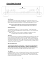
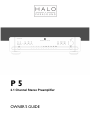
P5 2.1 Channel Stereo Preamplifier OWNER’S GUIDE Important Safety Instructions The lightning flash with the arrowhead symbol within an equilateral triangle is intended to alert the user to the presence of “dangerous voltage” inside the product that may constitute a risk of electric shock. The exclamation point within an equilateral triangle is intended to alert the user to the presence of important operating and maintenance instructions in the literature accompanying the product. TO REDUCE THE RISK OF ELECTRIC SHOCK, DO NOT REMOVE COVER. NO USER-SERVICEABLE PARTS INSIDE. REFER SERVICING TO QUALIFIED SERVICE PERSONNEL 1. Read Instructions — Read all the safety and operating instructions before operating this product. 2. Retain Instructions — Retain safety and operating instructions for future reference. 3. Heed Warnings — Adhere to all warnings on the product and in the operating instructions. 4. Follow Instructions — Follow all operating and use instructions. 5. Cleaning — Unplug this product from the wall outlet before cleaning. Use a damp cloth for cleaning. Clean the outside of the product only. 6. Attachments — Do not use attachments that are not recommended by the product manufacturer; they may be hazardous. 7. Water and Moisture — Do not use this product near water. 8. Accessories — Do not place this product on an unstable cart or stand. The product may fall, causing bodily injury and damage to the product. A product and cart combination should be moved with care. Quick stops, excessive force, and uneven surfaces may cause the product and cart to overturn. 9. Ventilation — Slots and openings in the cabinet are provided for ventilation to ensure reliable operation of the product and to protect it from overheating. These openings must not be blocked or covered. This product should not be placed in a built-in installation such as a bookcase or rack unless proper ventilation is provided. 10. Power Sources — Operate this product only from the type of power source indicated on the label. If you are not sure of the type of power supply to your home, consult your dealer or local power company. This product is equipped with a three-prong grounding plug. This plug will only fit into a grounding power outlet. If you are unable to insert the plug into the outlet, contact your electrician to replace your obsolete outlet. Do not defeat the safety purpose of the grounding plug. 11. Power Cord Protection — Power supply cords should be routed so that they are not likely to be walked on or pinched by items placed upon or against them. 12. Lightning — Unplug the unit from the wall outlet for added protection during a lightning storm and when it is left unattended and unused for long periods of time. This will prevent damage to the product due to lightning and power line surges. 13. Overloading — Do not overload wall outlets or extension cords. This can result in a fire or electric shock. 14. Inserting Objects into Unit — Never push objects of any kind into this product through any openings; they may touch dangerous voltage points or short out parts that could result in fire or electric shock. 15. Servicing — Do not attempt to repair or service this product yourself. Opening or removing covers may expose you to dangerous voltage and other hazards. Refer all servicing to qualified service personnel. 16. Damage Requiring Service — Unplug this product from the wall outlet and refer servicing to qualified service personnel under the following conditions: a) If the power-supply cord or plug is damaged. b) If liquid has been spilled into the product. c) If the product has been exposed to rain or water. d) If the product does not operate normally by following the operating instructions. e) If the product has been dropped or damaged in any way. f) If the product exhibits a distinct change in performance. 17. Replacement Parts — When replacement parts are required, be sure the service technician has used replacement parts specified by the manufacturer. Unauthorized substitutions may result in fire, electric shock, and other hazards. 18. Safety Check — Upon completion of any service or repairs to this product, ask the service technician to perform safety checks to determine that the product is in proper operating condition. 19. Wall or Ceiling Mounting — Mount the product to a wall or ceiling only as recommended. 20. Heat — The product should be situated away from heat sources such as radiators, heat registers, stoves, and other products (including amplifiers) that produce heat. 2 Table of Contents Introduction . . . . . . . . . . . . . . . . . . . . . . . . . . . . . . . . . . . . . . . . . . . . . . . . . Placement and Ventilation Guidelines . . . . . . . . . . . . . . . . . . . . . . . . . . . . . 5 . . . . . . . . . . . . . . . . . . . . . . . . . . . . . . . . . . . . . . . . . . . . 5 . . . . . . . . . . . . . . . . . . . . . . . . . . . . . . . . . . . . . . . . . . . . . . . 5 AC Mains Voltage . Rack Mounting Analog Audio Input Connections . . . . . . . . . . . . . . . . . . . . . . . . . . . . . . . . . 6 . . . . . . . . . . . . . . . . . . . . . . . . . . . . . . . . . . . . 8 . . . . . . . . . . . . . . . . . . . . . . . . . . . . . . . . . . . . . . . . . . . 9 Home Theater Bypass Input Digital Audio Inputs USB Computer Setup . . . . . . . . . . . . . . . . . . . . . . . . . . . . . . . . . . . . . . . . . . Audio Output Connections . Subwoofer Setup Turn On Options . 10 . . . . . . . . . . . . . . . . . . . . . . . . . . . . . . . . . . . . . 10 . . . . . . . . . . . . . . . . . . . . . . . . . . . . . . . . . . . . . . . . . . . . . 11 Main and Subwoofer Crossover Setup . . . . . . . . . . . . . . . . . . . . . . . . . . . . . 11 . . . . . . . . . . . . . . . . . . . . . . . . . . . . . . . . . . . . . . . . . . . . . 13 Other Rear Panel Connections . Front Panel Operation. . . . . . . . . . . . . . . . . . . . . . . . . . . . . . . . . . . 14 . . . . . . . . . . . . . . . . . . . . . . . . . . . . . . . . . . . . . . . . . 15 Remote Control Functions Problem and Remedies . . . . . . . . . . . . . . . . . . . . . . . . . . . . . . . . . . . . . . 17 . . . . . . . . . . . . . . . . . . . . . . . . . . . . . . . . . . . . . . . . 19 If You Require Assistance or Warranty Repair Specifications . 4 . . . . . . . . . . . . . . . . . . . . . . . 20 . . . . . . . . . . . . . . . . . . . . . . . . . . . . . . . . . . . . . . . . . . . . . . . 21 3 INTRODUCTION Thank You for Choosing Parasound Your new Parasound Halo P 5 is an advanced 2.1 channel stereo preamplifier that has been designed for the most advanced performance for serious two channel music listening and ease of integration with a surround sound system. The P 5 is built to the extremely strict quality and performance standards for which Parasound is renowned. We’re proud to offer you this exceptional audio component that will bring you many years of enjoyment and dependability. Because your new Halo Series P 5 Preamplifier performs at a higher level of sonic performance than you may have expected we encourage you to read this entire manual to maximize your enjoyment. We wish you many years of listening enjoyment. -The Parasound Staff Keeping Records for Future Reference Record the serial number located on the back panel or bottom of your P 5 in the space below. Also note your Parasound Dealer’s name and telephone number. Your purchase receipt/bill of sale is required to determine if your P 5 is eligible for Parasound warranty service. We recommend that you make an extra copy of your original purchase receipt/bill of sale and store it inside the P 5’s carton. Parasound P 5 Amplifier Serial #: ______________ (5 digit number below the bar code) Parasound Dealer: ___________________________________________________ Parasound Dealer Phone Number: ___________________ Date of Purchase: ______________________ Important Warranty information There is no Parasound warranty for this unit if it was not purchased from an Authorized Parasound Dealer. Investigate warranty coverage statements made by an unauthorized dealer very carefully, as you will need to depend entirely upon your dealer, and NOT upon Parasound. Unauthorized dealers lack the capability to make repairs or arrange for repairs of Parasound equipment. A list of Authorized Parasound Dealers and detailed warranty information is available at www.parasound.com or you can call 415-397-7100 between 9:00 am and 4 pm Pacific time. A missing or altered serial number could indicate that this unit was re-sold by an unauthorized dealer or is stolen merchandise. If this unit is missing its serial number or the serial number has been altered, you should return it to your dealer immediately for a full refund. 4 Unpacking Your P 5 & Placement Guidelines Unpacking Your P 5 Carefully remove your P 5 from its shipping carton and locate the enclosed accessories: • AC power cord • Two trigger wires, one with mono 3.5 mm mini plugs, one with a mono 2.5mm sub-mini plug and a mono 3.5mm mini plug • Remote Control with AAA batteries • USB A to USB B cable for music playback from a computer • Stereo cable with stereo 3.5mm mini plugs for using the front panel AUX input While you are unpacking your P 5, inspect it thoroughly for possible shipping damage and tell your Parasound dealer immediately if you find any evidence of shipping damage. This would be a good time to make a copy of your sales receipt to store with the P 5’s original packing. Note: Please save and store both the inner and outer cartons and, most especially, the foam packing inserts to protect the P 5 if you have to move it or ship it. You may wish to flatten the cardboard cartons to save room in storage after cutting the taped seams on the bottom flaps. Placement Guidelines The P 5 will be easier to use and will last longer if you follow these simple guidelines: • Use input and output cables that are long enough to leave some slack; that will enable you to pull the P 5 out of a cabinet to check or to change connections without inadvertently disconnecting cables. • Place your P 5 where you can route input and output signal cables as far as possible from any AC cords. • Where signal cables must cross AC cords they should do so only at a 90° right angle. Ventilation Requirements • Always position the P 5 horizontally. • The P 5 should never be stacked above a power amplifier. • The P 5 should not be placed in a completely enclosed cabinet. AC Mains Voltage The P 5 will operate on AC mains voltage of 100V-240V. There is no need for any fuse or wiring changes to switch between 115V and 230V operation. Rack Mounting your P 5 With its four feet removed, the P 5’s front panel height occupies two rack spaces: 3.5” or 88.2 mm. (A single standard rack space occupies 1.75” vertical space.) For mounting in a standard 19” equipment rack, you must use the Parasound HRA 2 rack mount kit (purchased separately). The HRA 2 kit includes four bolts and eight plastic washers with raised “shoulders.” Slide one washer onto each mounting bolt with its raised shoulder pointing toward the panel hole. Insert the bolt through the hole and slide the other washer on the bolt with its raised shoulder facing the rear side of the panel. The washers will sandwich the P 5 panel and the four mounting bolts to prevent metal-to-metal contact between the P 5 chassis, the equipment rack, and the other components mounted in the rack. Warning: Do not put the screws for the feet back into the bottom of the P 5 without the feet. Doing so could cause the screws to touch electrical components and cause a short circuit. 5 Analog Audio Input Connections Always disconnect your P 5's AC cord before making or changing any input, output or trigger wire connections. Inserting or removing an input or output cable while the P 5 is turned on can result in a blast of sound that could damage your loudspeakers. Make sure there is no strain or tension on any cables that could cause them to pull loose. Phono Input The P 5 is equipped with a high quality phono preamplifier. If you wish to connect a turntable, set the Load/Cartridge switch to MM (moving magnet) or MC (100 Ω or 47k Ω moving coil), depending on your cartridge type. Select MM if you are not sure which type of phono cartridge you have because MM cartridges are more common. If you use the MC setting with an MM cartridge the volume level will be very high and distorted. Only a turntable can be connected to the Phono input. Phono Load/Cartridge Switch The Phono input has a 3 position load/cartridge selector switch. Select the switch position that matches your turntable cartridge type. We recommend that you contact the cartridge manufacturer if you are unsure which setting is best for your equipment. You may also try all three settings and use the setting which sounds the best in your system and listening room. . MM is for moving magnet cartridges. It provides a 47k ohm load and the appropriate gain for all MM cartridges. This is the most common cartridge type. MC 100 Ω is for most moving coil cartridges. It provides the higher gain required for even very low output MC cartridges and a 100 ohm load that is ideal for the majority of MC cartridges. MC 47k Ω provides the appropriate gain for MC cartridges with an alternative 47k ohm load. You can try both the 100 Ω and 47k Ω settings to see which sounds best in your system. The MC 47k Ω setting is also the load Grado recommends for their MI (moving iron) cartridges. Note: If your turntable won’t reach adequate volume, or if it plays too loud, you have selected the incorrect cartridge type. Don’t forget to connect the ground wire from your turntable to the Phono GND (ground) terminal on the P 5. 6 Analog Audio Input Connections (Continued)… RCA line level Input Jacks (inputs 1-5) Source inputs 1–5 all have the same input sensitivity and input impedance and they are compatible with any typical analog line level source. Note: Input 5 is shared with the XLR balanced input, therefore the RCA and XLR jacks for input 5 should not be connected at the same time. XLR Balanced Input (input 5) Input 5 uses balanced XLR type jacks. Use this input to connect an analog source which has balanced outputs. A balanced line provides superior hum and noise cancellation, especially for long cable runs. Note: Input 5 is shared with the XLR balanced input, therefore the RCA and XLR jacks for input 5 should not be connected at the same time. Front Panel Aux Input For your convenience there is an input jack on the front panel for a portable MP3 player (or smart phone). Connect the included cable with 3.5mm stereo plugs between the portable player or smart phone’s headphone jack and the P 5’s Aux input jack. The Aux input has an additional gain stage that boosts the input signal by 12dB so that the volume level remains consistent when you select your other source components. For the best result set your portable player’s volume to at least 75% of its maximum level. Note: If you connect a component other than a portable MP3 player to the Aux Input jack, the volume level will probably be too high and possibly distorted. 7 Home Theater Bypass Input The Bypass input jacks are used to incorporate the P 5 into a surround sound system. This enables you to use the power amplifier (or two channels of a multi-channel amp) driving your Left and Right front speakers and subwoofer(s) with stereo sources connected to the P 5 and with your surround sound system. The Bypass input works by passing the incoming L, R and Sub channels directly through to the L, R and Sub output jacks. None of the P 5 circuits or controls has any effect on the bypassed signals. The P 5 is thus transparent to the Left, Right and Subwoofer(s) outputs from your surround sound processor or receiver and passes them on to your amplifier(s) and Subwoofer(s). Note: In order to use the P 5 Bypass function your surround sound receiver must have line level preamp output jacks. The P 5’s Bypass function is a direct connection between its L, R and Sub Bypass Input jacks and its Main and Sub output jacks. All controls are excluded from the bypass signal path. Adjusting the P 5 Volume will not change the volume level of the Bypass input The Bass and Treble Tone controls do not function; frequency response is flat, regardless of how these controls are adjusted. The Left/Right Balance control does not function; channel balance is equal, regardless of how this control is adjusted. The Main Outputs are full range, regardless of the crossover settings The Sub Outputs are full range, regardless of the crossover settings The exclusions above are intentional so your surround sound receiver (or processor)’s bass management menu settings and volume control) function normally when you are listening to surround sound with the Left, Right and Sub channels routed through the P 5. Please see the owner’s manual for your surround sound receiver or processor to set the proper speaker levels, distance and bass management. If you have already calibrated your surround sound system, there is no need to recalibrate your system after adding the P 5. Don’t forget that the volume control on the P 5 does not work when the Bypass Input is selected. Use the volume control on your surround sound AVR or processor. Connecting the Bypass Input Connect your surround sound receiver’s Left, Right & Sub(s) preamp output jacks to the P 5’s Left, Right & Sub(s) Bypass Input jacks. With a single subwoofer you can use either the Sub 1 or Sub 2 Input jacks. Note: Two Bypass Subwoofer Input jacks are included in case you have two subwoofers and your surround receiver includes two Subwoofer out jacks. Selecting the Bypass Input The Bypass Input can be selected by two different methods: P 2 is Already Turned On: When the P 5 is turned on you can select the Bypass input with the remote control or the front panel Input selector knob. P 2 is Turned Off: The Bypass input is automatically selected whenever the P 5 is turned off. This makes it easy to use your surround sound equipment even without turning the P 5 on. Note: Do not connect a source component such as a cd player, blu-ray player, tape deck or tuner directly to the bypass input. Since there is no volume control with this input the full voltage output of the source will go directly to the power amplifier. The sound level could be extremely high and could damage your speakers and hearing. 8 Digital Inputs (OPT, COAX, USB) The P 5’s built in DAC (Digital to Analog Converter) uses a high resolution 192kHz Burr-Brown DAC IC. Since the P 5’s DAC is superior to the DAC in most source components. They will sound better if you connect their digital output to the P 5 instead of using its conventional analog line output. Opt (Optical) The optical input is a high speed Toslink receiver with a 25MHz bandwidth. It accepts these standard sampling rates: 8 kHz, 11.025 kHz, 16 kHz, 32 kHz, 44.1 kHz, 48 kHz, 88.2 kHz, 96 kHz, 176.4 kHz and 192 kHz. It accepts 16 bit and 24 bit word lengths. Optical Cable Note: 176.4 kHz and 192 kHz sampling rates will only play reliably with a very short optical cable. Be careful when handling the optical cable. It has limited flexibility and it cannot be bent at a sharp angle without impairing its ability to transfer the digital signal from your source to the P 5. Coax (Coaxial) The Coax (also called S/PDIF) input connector is an RCA jack. The Coaxial input accepts these standard sampling rates: 8 kHz, 11.025 kHz, 16 kHz, 32 kHz, 44.1kHz, 48kHz, 88.2kHz, 96 kHz, 176 kHz & 192 kHz. It accepts 16 bit and 24 bit word lengths. USB The USB input is used to connect your P 5 to your PC or Mac computer. This allows high quality playback of any music that is stored on your computer and streaming music services accessed over the internet. The USB accepts sampling rates of 44.1 kHz, 48 kHz, 88.2 kHz and 96 kHz. It accepts 16 bit and 24 bit word lengths. The P 5 uses the USB 1.1 Audio standard which allows use of 15’ (5 m) USB cables without any performance penalty. USB Cable Note: Use a high quality USB cable for the best results. This is particularly important for cables that are more than 6' (2 m) long. Inexpensive, long USB cables are often unreliable and could cause drop outs. Using a Blu-ray or DVD Player's Digital Output If you use a Blu-ray, DVD player, Cable Box or Satellite Receiver’s digital output with the P 5 you must go to its setup menu and set the player’s digital audio output to Stereo PCM (2.0). The P 5 accepts only two-channel stereo PCM. It does not accept Dolby, DTS or DSD format signals. 9 USB - Computer Setup First, turn on your computer, then connect the USB cable (included in the P 5 carton) and then turn on the P 5. The first time you connect your P 5 to a computer it will automatically install the correct drivers. Next you will need to ensure that the P 5 is set as the computer’s default audio output device. Follow these instructions to assign the P 5 as the default audio device: For a Windows® PC - Right click on the loudspeaker icon in the bottom right of your screen (on the tool bar) - Select “Playback Devices” - When the “Sound” window pops up click on the “PARASOUND P 5” and then click “Set as Default” - Click “OK” to close the “Sound” window Note: If for some reason you cannot find the loudspeaker icon you will need to go to the sound options in the Control Panel and select the P 5 as the default playback device. For a Mac® with OS X - Go to the Apple Menu - Select “System Preferences” - Select “Sound” from the Hardware Menu - Select “PARASOUND P 5” in the Sounds Menu Playing Music From Your Computer Once initial setup is complete your P 5 will be ready for use with your PC or Mac. Press the USB button on the P 5’s remote control or rotate the P 5’s Input select knob until the blue indicator for USB is illuminated. Simply start playing any music on your computer and it will be sent to the P 5 via the USB cable. Any sound that you would normally hear through your computer speakers will be heard through the P 5 and your accompanying audio system. Note: For the highest quality sound playback we recommend leaving your computer’s volume control at 100%. Then use the volume control on your P 5 to set the listening level. Audio Output Connections Left and Right Main Output Jacks (Balanced and Unbalanced) The Main Output Jacks are the primary outputs that connect to the inputs on your power amplifier. Both RCA (unbalanced) and XLR (balanced) connections are provided. Subwoofer Outputs (Balanced and Unbalanced) The P 5 provides convenient, high quality connections for one or more subwoofers. All of the subwoofer outputs carry the same mono signal. This mono signal can be full range or crossed over depending on the setting of the Low Pass crossover. Record Out Jacks The Record Out jacks connect to your audio recorder’s record/input jacks. When you select an Input the signal from the corresponding source component is available at the Record Out jacks whenever the P 5 is turned on. It is a fixed level signal that is unaffected by volume, balance, tone settings, audio mute or crossover settings. Note: When you select the Bypass Input, there is no signal available at the Record Out jacks. The P 5 does not offer simultaneous monitoring of a recording while you are making it. 10 Subwoofer Setup There are two important steps in setting up your sub(s). These are crossover setup and level setup. Subwoofer Crossover Setup You will want to turn off the crossover built into your subwoofer since the P 5 has its own crossovers and leaving both crossovers on would result in double filtering. Most subwoofers have a switch to accomplish this. This switch is sometimes called “Bypass”, “Home Theater” or simply “Crossover Off.” If your subwoofer’s crossover cannot be switched off, set it to its highest frequency. Now follow the crossover setup section of this manual for the proper settings on the P 5. Subwoofer Level Setup To set the proper subwoofer level, first set the P 5’s front panel Sub Level control to the 12 o’clock (0 dB) position and then play a variety of music. Adjust the level control built into your subwoofer until the bass level sounds balanced. Now, whenever you want to fine tune your subwoofer level you can simply use the P 5's front panel Sub Level control instead of walking over to your sub, bending down and reaching behind it to adjust its level control. Main and Subwoofer Crossover Setup The P 5 is equipped with adjustable Low Pass and High Pass crossovers. Crossovers are filters that allow certain frequencies to pass while blocking other frequencies. A Low Pass filter permits low frequencies to pass and blocks high frequencies. A high pass filter permits only high frequencies to pass and blocks low frequencies. 80Hz is the best starting frequency for both the High and Low Pass crossovers if you are using a subwoofer and are not sure where to set the crossover frequency. If you are not using a subwoofer, set the Main Output Crossover switch to the Off position. Both XLR (balanced) and RCA (unbalanced) outputs are affected by the crossover settings. Low Pass Crossover (Subwoofer Outputs) The low pass crossover allows only low frequencies to be output at the P 5 Subwoofer output jacks and then played by your subwoofer(s). Note: If your subwoofer has a built-in crossover that cannot be switched off, set it to its highest frequency to minimize the negative effects on bass response from filtering in the P 5 and again in the subwoofer. High Pass Crossover (Left and Right Main Outputs) The High Pass crossover for the Left and Right Main outputs allows you to keep low frequencies from going to your main L and R speakers. This can be particularly useful if you are using small speakers (typically their woofers are 6.5” inches or smaller) and you have a subwoofer. The most common settings are between 50Hz and 80Hz. If you are not using a subwoofer you will get the best results by turning the High Pass crossover off or setting it to under 40Hz. If you want your L and R speakers to operate full range with no frequencies blocked set the High Pass crossover switch to its Off position. 11 Crossover Setup (Continued)… Crossover On/Off Switches: Sub Output Crossover Off Full Range signals will be sent to the sub. You will need to adjust the crossover frequency on the crossover that is built into your subwoofer. Sub Output Crossover On The highest frequency going to the Sub is determined by the setting of the Low Pass frequency knob. Main Output Crossover Off Full Range signals will be sent to the Left and Right speakers. Main Output Crossover On The lowest frequency going to the Left and Right speakers is determined by the setting of the High Pass frequency knob. Crossovers and the Bypass Input The High and Low Pass Crossovers are always off when the Bypass Input is selected. In this case the high and low pass filters are not active because you will want to use the bass management you already selected in your surround sound receiver’s setup menu. Where to start with Crossover settings If you don’t know where to set the High and Low Pass Crossovers, these settings are a good place to start. From here you can experiment until you find a combination that sounds best to you: No subwoofer Set the High Pass Crossover switch to Off The Low Pass Crossover will not be used so this setting does not matter When using one or more subwoofers and your Left and Right speakers' woofers are 6.5” or smaller Set the High Pass Crossover switch to On and the frequency knob to 80Hz Set the Low Pass Crossover switch to On and the frequency knob to 80Hz When using one or more subwoofers and your Left and Right speakers' woofers are larger than 6.5” Set the High Pass Crossover switch to On and the frequency knob to 50Hz Set the Low Pass Crossover switch to On and the frequency knob to 50Hz 12 Turn On Options For convenience, there are three ways the P 5 can be turned on and off: Manual - Press the On-Off button on the front panel or the On and Off buttons on the remote control. Automatic - When a 12V trigger voltage is applied to the 12V input jack. Automatic - Whenever the P 5’s AC power source is live. Note: When either automatic turn on option is selected the front panel On-Off button is disabled so that power on/off is determined solely by the triggering device or live AC power. Turn On Options Switch: Manual Position When the Turn On Options switch is in its Manual position, the Turn On Options automatic functions are disabled and the P 5 must be turned on and off manually by pressing the OnOff button on its front panel every time you wish to use your audio system. 12V Position (Automatic on/off) When the Turn On Options switch is set to its 12V position, the P 5 is turned on and off only with an external +9 V to + 12 V voltage from your preamp or AV Receiver. When the external voltage ceases the P 5 will turn off immediately. The 12V switch position disables the front panel On-Off button. AC Power Trigger The P 5 will turn on automatically when its AC power source is switched on. Note: When the Auto Turn On switch is set to 12V or AC the front panel On-Off button and remote control On and Off buttons are disabled. 3.5mm Mini Jack and 2.5mm Sub-mini Jacks Some models of Parasound power amplifiers and preamplifiers use 2.5mm “sub-mini” trigger jacks. To use the P 5 with these models we include a trigger wire with a 3.5mm plug at one end and a 2.5mm plug at the other end. 13 Other Rear Panel Connections IR Input Your P 5 is compatible with most popular infrared repeater systems for remote control operation from another room or when the P 5 is installed in a cabinet where its remote handset signals cannot reach its front panel remote control sensor. The External Remote Input connector is a standard 1/8” (3.5 mm) mono “mini” jack. The center conductor (plug tip) is for signal and the outer conductor (plug sleeve) is for ground. Your Authorized Parasound dealer or custom installer can recommend a compatible IR repeater system. IR Loop Output The loop output offers a convenient way to daisy chain an IR signal to another piece of equipment. Whatever IR control signal is present at the rear panel IR Input jack will also be present at the IR Loop Out jack. AC Power Cord The AC cord supplied with your P 5 is a high quality IEC type cord. If possible, plug your P 5 into the same AC outlet that your source components and power amplifier are plugged into. If different AC outlets are used for the P 5 and these other components the ground potential may be higher or lower between the outlets, resulting in audible hum. 14 Front Panel Controls On-Off Button A soft blue glow surrounds the On-Off button when the P 5 is turned off. Push the On-Off button once to turn on and the blue glow will get brighter. When the P 5 is turned on, the Input indicator and Mute button will illuminate blue. Push the On-Off button again to turn it off. Note: The front panel On-Off button and remote control On and Off buttons are disabled when the rear panel Turn On Options switch is set to 12V or AC. Headphone Output The headphone jack accepts a 1/8” (3.5 mm) stereo mini plug. The Left, Right and Sub outputs are muted when a headphone plug is inserted into this jack. The L and R Record out jacks are not muted. Note: Please note the volume level before unplugging your headphones to avoid unexpected high level sound that could damage your speakers. Aux Input For your convenience there is an input for a portable MP3 player (or smart phone) on the front panel. Connect the included cable with 3.5mm stereo plugs between the portable player or smart phone’s headphone jack and the P 5’s Aux input jack. The Aux input has an additional gain stage that boosts the input signal by 12dB so that the volume level will remain consistent as you listen to your other source components. For the best results set your portable player’s volume to at least 75% of its maximum. Bass and Treble Knobs These offer precision adjustment of tonal balance. You will find that very slight adjustments can add a degree of warmth, richness, clarity and “air.” However, greater adjustments may obscure musical detail, and even risk overloading your speakers. The Bass and Treble Controls are only active when the blue light surrounding the Tone button is illuminated. The Bass and Treble controls affect both the Main Outputs and the Subwoofer outputs. Tone Button By pressing this button, you can turn off the Bass and Treble tone controls, thereby completely bypassing the tone control circuitry. This will improve sonic purity by eliminating the small amount of noise and distortion inherent in tone control circuits. The tone controls can also be turned on and off from the remote control. 15 Front Panel Controls (Continued)… Input Knob Rotating the Input selector will cycle through all of the inputs. The front panel LED under each input will indicate when it is selected. Sub Level Knob The Sub Level control knob adjusts the subwoofer level. The sub level can be adjusted between -10 dB and +10 dB, relative to the L and R channels. When the control knob is in the 12 o’clock position the sub level boost is 0 dB. When you first set up your subwoofer you should set this control to 12 o’clock (0 dB) and then play some music. Adjust the level control built into your subwoofer until it sounds balanced. Now, whenever you want to fine tune your subwoofer level you can simply use the front panel Sub Level control instead walking over to your sub and bending over to adjust the level control on the subwoofer. Note: The Sub Level knob does not adjust the Sub level when the Bypass Input is selected. Balance Knob Adjusting left and right channel balance is helpful to compensate for speaker placement, room acoustics or if your power amplifier’s gain isn’t identical for both channels. Volume Knob Your P 5 uses a high quality Alps potentiometer to adjust the master volume level. The potentiometer is motorized for remote control use. Mute Button Pressing the Mute button once will mute the signal at all of the Out jacks except the Record Out. The Mute button will turn red while mute is engaged. Press the Mute button a second time to cancel mute. The Mute will be automatically canceled if you press the volume up or down buttons on the remote. Note: Mute is not canceled when you turn the front panel Volume knob. Refrain from moving the Volume knob when the P 5 is muted to avoid a loud surprise when it is unmuted. 16 Remote Control Functions The P 5 remote control has a maximum range of approximately 20 - 25 feet (6 - 7.5 meters). Use only AAA alkaline batteries in the handset and insert them according to the + and – polarity markings in the battery compartment. On and Off Buttons These separate buttons enable programming unambiguous “hard” off and on commands into a system controller or to create a macro sequence for a learningtype remote control. Note: The On and Off buttons are disabled when the rear panel Turn On Options switch is set to 12V or AC. Mute Button Pressing the Mute button once mutes the signal at all of the Out jacks except the Record Out. The Mute button on the front panel will illuminate red while mute is engaged. Press the Mute button a second time to cancel mute. Volume ▲ and ▼ Buttons These buttons control the rotation of the motorized Volume knob to increase and decrease listening volume levels. Tone On and Off Buttons By pressing the Tone On button you engage the tone control circuit with the boost or cut determined by the setting of the front panel Bass and Treble knobs. By pressing the Tone Off button you can turn off the Bass and Treble tone control circuit, thereby completely bypassing the tone control circuitry. This will improve sonic purity by eliminating the small amount of noise and distortion inherent in tone control circuits. The tone controls can also be turned on and off from the front panel. Note: The remote control cannot make Bass and Treble adjustments. Tone adjustments are only made with the Bass and Treble knobs on the P 5’s front panel. Source Input Buttons Press the input button of the source that you wish to hear. 17 Maintaining Your P 5 Your P 5 requires no periodic maintenance and has no user serviceable parts inside. To avoid risk of electric shock do not remove the top cover. To keep it clean use only a soft cloth moistened with a few drops of clear water or Windex. Never use any solvents or abrasives. The remote control handset batteries should be removed whenever it will be unused for an extended period. Remove the battery cover annually to inspect and remove leaking batteries. Ground Loops - Eliminating Hum and Buzz Audible hum and buzzing noises in a system are usually related to issues with the component grounds. Ground (sometimes called common) is a point of reference for voltages in virtually all audio and video components. Ground is supposed to remain at zero volts while the audio signal swings positive (voltage above ground) and negative (voltage below ground). If ground isn’t at zero, there can be an audible 60 Hz hum (or 50 Hz hum in regions with 50 Hz AC). The harmonics of these frequencies (120 Hz, 240 Hz, 480 Hz or 100 Hz, 200 Hz, 400 Hz) may add buzz in addition to the hum. The ideal of zero voltage ground for all the components in a system is practically impossible, because some resistance between the ground points of different components is inevitable. By keeping components close together with their power cords plugged into a common AC outlet or power strip, you’ll avoid the problems created by resistance in the house’s wiring. Hum and buzz is also caused when unwanted voltage flows through multiple component ground points called ground loops. Here are three tips to avoid ground loops: 1. Your Cable TV receiver box might require a Cable TV ground isolator. To determine if this is the case, unplug your incoming cable signal and see if the buzz/hum goes away. 2. Plug your subwoofer and amplifier(s) into the same outlet as the P 5. 3. When rack mounting, always use the insulated “shoulder” washers. These break the ground loops caused by metal-to-metal contact between the rack, the components, and their rackmount bolts. 18 Problems and Remedies Why is there no sound from the speakers? - Is the AC power live? You should see a faint red glow around the Power button even when the unit is turned off. - Check that input and output cables are secure at both ends. - Make sure your P 5 is switched to the correct input. - Make sure your power amplifier is powered on. The P 5 won’t turn on - Make sure the rear panel Turn On Options Switch is set to the Manual position. - Make sure the rear panel master power switch is turned on. -Make sure the unit is plugged into a live AC receptacle The P 5 won’t turn off - Make sure the rear panel Turn On Options Switch is set to the Manual position. I can hear a background hum from the speakers - Read the section on ground loops in this manual. - Move audio cables and AC cords away from each other (while power is off). - Try to route audio cables and AC cords perpendicular to each other (while power is off). - Make sure insulating shoulder washers are used if unit is rack mounted. - Insure that the power amps and the P 5 are plugged into the same AC outlet. - Try unplugging the incoming Cable TV line. If the noise goes away you need a cable TV ground isolator. - Try plugging your subwoofer into the same outlet as the P 5 and power amp. - The turntable ground wire must be attached to the GND terminal. The sound is distorted and weak - Make sure the gain of the power amp is not set too low. - Are you trying to use P 5 with a turntable? Make sure you have set the phono selector switch to the correct cartridge type. Is the turntable's tracking force adjusted correctly for its cartridge? - Make sure the stereo power amp’s stereo/mono switch is set to stereo. When I use the Bypass Input the sound is very loud and cannot be turned down. The Bypass input should never be connected directly to a source component (CD, DVD, Tape deck, etc.). It should only be used in conjunction with a surround sound receiver or controller. The volume control on the surround sound equipment should be used to adjust the volume level when the P 5 Bypass input is selected. What is the Bypass Input? The Bypass input jacks are used to incorporate the P 5 into a surround sound system. This enables you to use the power amplifier (or two channels of a multi-channel amp) driving your Left and Right front speakers and subwoofer(s) with stereo sources connected to the P 5 and with your surround sound system. 19 Are You Having Difficulty? Repair or Service Call your Parasound dealer first. If the dealer can’t help you with your problem we encourage you to call Parasound’s Technical Service Department at 415-397-7100, Monday - Friday, 8am - 4pm Pacific Time. We can suggest other diagnostic tests you can easily perform. If we determine that your P 5 should be returned to Parasound or an Authorized Parasound Warranty Center for inspection and possible servicing, we will provide the location of a warranty center near you or shipping instructions for the unit’s return to Parasound. Before You Return Any Unit to Parasound for Service Before you send your unit to Parasound, you will need to obtain a specific Return Authorization (RA) number and shipping instructions from Parasound’s Technical Department. The RA number must be clearly marked on the outer carton. Use the original factory packing materials and arrange adequate insurance to cover its value. You must include a copy of your purchase receipt, since this document establishes the validity of this unit’s warranty. Warranty repairs are only performed by Parasound or Parasound Authorized warranty centers when your purchase receipt is from a Parasound Authorized Dealer or Parasound Authorized Reseller. Shipments Will Be Refused by Parasound Under the Following Conditions: 1. Unit was sent without the Parasound-assigned RA number marked on the carton. 2. Unit was sent in an unsuitable shipping carton and packing inserts and is likely to have been damaged in transit. 3. Unit has inadequate packing materials and is likely to have been damaged in transit. Wrapping the P 5 with bubble wrap will not protect it during shipment. 4. Unit was shipped collect for shipping charges. We do not accept collect shipments. 5. Unit was shipped via the US Postal Service. 6. Unit was sent to an address other than the address instructed by our Technical Department. Warranty Repair Please read your accompanying Parasound Limited Warranty carefully to understand the applicable rights and limitations. This section provides instructions for obtaining repairs, both for units covered under the Parasound Limited Warranty and for units or situations which are outside the Warranty. The complete warranty can be found at www.parasound.com. Unit is not eligible for repair under the terms of the Parasound warranty if: 1. Unit was not purchased from a Parasound Authorized Dealer. 2. You do not have the original bill of sale or sales receipt from a Parasound Authorized Dealer. 3. You are not the original owner. The Parasound warranty is not transferable. 4. Unit’s serial number was removed, modified, or defaced. 5. Unit shows evidence of abuse and/or misuse. 6. Unit was modified in any way. 7. A prior repair was attempted by an unauthorized repair station. 20 Specifications Frequency Response 10 Hz - 100 kHz, +0/-3 dB Hi & Low Pass Crossover Slope 12 dB / Oct Total Harmonic Distortion < 0.01 % DC Trigger Requirements +9 Vdc to +12 Vdc, 2 mA Crosstalk > 70 dB at 20 kHz XLR Pin Identification 1 = Ground (Shield) 2 = Positive 3 = Negative (Return) Input Sensitivity 300 mv: 1 Volt Out Total Gain: 10 dB Maximum Output: 7 Volts Dimensions Width: 17-1/4” (437 mm) Depth: 13-3/4” (350 mm) Height, with feet: 4-1/8” (105 mm) Height, without feet: 3-1/2” (89 mm) Input Impedance Unbalanced: 24k Ω Balanced: 100k Ω per leg Net Weight 14 lb. (6.3 kg) Output Impedance Unbalanced: 100 Ω Balanced: 470 Ω per leg Shipping Weight 21 lb. (9.5 kg) S/N Ratio - Line Inputs 1- 5 > 108 dB, input shorted, IHF A-weighted > 88 dB, input shorted, unweighted Power Requirement Standby: 0.5 Watts Power On: 12 Watts 100-250 Volts, 50-60 Hz (Automatic) S/N Ratio - DAC Inputs > 108 dB, input shorted, IHF A-weighted > 90 dB, input shorted, unweighted S/N Ratio - Phono Inputs MM > 80 dB, input shorted, IHF A-weighted MM > 70 dB, input shorted, unweighted MC > 67 dB, input shorted, IHF A-weighted MC > 55 dB, input shorted, unweighted Specifications and features subject to change or improvement without notice. Copyright Parasound Product Inc., 2013 Rev. 1.1 www.parasound.com 21 Parasound Products, Inc. 2250 McKinnon Ave, San Francisco, CA 94124 415-397-7100 / Fax 415-397-0144 www.parasound.com 22