1
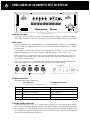
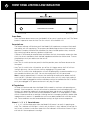
Protect 1 2 3 4 5 Hi Temp Power Model 5125 Five Channel Amplifier Five Channel Amplifier OWNER’S GUIDE IMPORTANT SAFETY INSTRUCTIONS The lightning flash with the arrowhead symbol within an equilateral triangle is intended to alert the user to the presence of “dangerous voltage” inside the product that may constitute a risk of electric shock. The exclamation point within an equilateral triangle is intended to alert the user to the presence of important operating and maintenance instructions in the literature accompanying the product. TO REDUCE THE RISK OF ELECTRIC SHOCK, DO NOT REMOVE COVER. NO USER-SERVICEABLE PARTS INSIDE. REFER SERVICING TO QUALIFIED SERVICE PERSONNEL 1. Read Instructions — Read all the safety and operating instructions before operating this product. 2. Retain Instructions — Retain safety and operating instructions for future reference. 3. Heed Warnings — Adhere to all warnings on the product and in the operating instructions. 4. Follow Instructions — Follow all operating and use instructions. 5. Cleaning — Unplug this product from the wall outlet before cleaning. Use a damp cloth for cleaning. Clean the outside of the product only. 6. Attachments — Do not use attachments that are not recommended by the product manufacturer; they may be hazardous. 7. Water and Moisture — Do not use this product near water. 8. Accessories — Do not place this product on an unstable cart or stand. The product may fall, causing bodily injury and damage to the product. A product and cart combination should be moved with care. Quick stops, excessive force, and uneven surfaces may cause the product and cart to overturn. 9. Ventilation — Slots and openings in the cabinet are provided for ventilation to ensure reliable operation of the product and to protect it from overheating. These openings must not be blocked or covered. This product should not be placed in a built-in installation such as a bookcase or rack unless proper ventilation is provided. 10. Power Sources — Operate this product only from the type of power source indicated on the label. If you are not sure of the type of power supply to your home, consult your dealer or local power company. This product is equipped with a three-prong grounding plug. This plug will only fit into a grounding power outlet. If you are unable to insert the plug into the outlet, contact your electrician to replace your obsolete outlet. Do not defeat the safety purpose of the grounding plug. 11. Power Cord Protection — Power supply cords should be routed so that they are not likely to be walked on or pinched by items placed upon or against them. 12. Lightning — Unplug the unit from the wall outlet for added protection during a lightning storm and when it is left unattended and unused for long periods of time. This will prevent damage to the product due to lightning and power line surges. 13. Overloading — Do not overload wall outlets or extension cords. This can result in a fire or electric shock. 14. Inserting Objects into Unit — Never push objects of any kind into this product through any openings; they may touch dangerous voltage points or short out parts that could result in fire or electric shock. 15. Servicing — Do not attempt to repair or service this product yourself. Opening or removing covers may expose you to dangerous voltage and other hazards. Refer all servicing to qualified service personnel. 16. Damage Requiring Service — Unplug this product from the wall outlet and refer servicing to qualified service personnel under the following conditions: a) If the power-supply cord or plug is damaged. b) If liquid has been spilled into the product. c) If the product has been exposed to rain or water. d) If the product does not operate normally by following the operating instructions. e) If the product has been dropped or damaged in any way. f) If the product exhibits a distinct change in performance. 17. Replacement Parts — When replacement parts are required, be sure the service technician has used replacement parts specified by the manufacturer. Unauthorized substitutions may result in fire, electric shock, and other hazards. 18. Safety Check — Upon completion of any service or repairs to this product, ask the service technician to perform safety checks to determine that the product is in proper operating condition. 19. Wall or Ceiling Mounting — Mount the product to a wall or ceiling only as recommended. 20. Heat — The product should be situated away from heat sources such as radiators, heat registers, stoves, and other products (including amplifiers) that produce heat. www.parasound.com TABLE OF CONTENTS Introduction . AC Voltage . 1 . . . . . . . . . . . . . . . . . . . . . . . . . . . . . . . . . . . . . . . . . . . . . . . . . . . 2 . . . . . . . . . . . . . . . . . . . . . . . . . . . . . . . . . . . . . . . . . . . . . . . . . . . . 3 Ventilation Requirements . Rack Mounting . . . . . . . . . . . . . . . . . . . . . . . . . . . . . . . . . . . . . . . . . . 3 . . . . . . . . . . . . . . . . . . . . . . . . . . . . . . . . . . . . . . . . . . . . . . . . . 3 Rear Panel Connections and Controls . . . . . . . . . . . . . . . . . . . . . . . . . . . . . . . . . . . 4 . . . . . . . . . . . . . . . . . . . . . . . . . . . . . . . . . . . . . 8 . . . . . . . . . . . . . . . . . . . . . . . . . . . . . . . . . . . . . . . 9 . . . . . . . . . . . . . . . . . . . . . . . . . . . . . . . . . . . . . . . . . . . 10 . . . . . . . . . . . . . . . . . . . . . . . . . . . . . . . . . . . . . . . . . . . . . . . . . 10 Front Panel Controls and Indicators. Typical Problems and Remedies. If You Require Assistance Warranty Repair Specifications . . . . . . . . . . . . . . . . . . . . . . . . . . . . . . . . . . . . . . . . . . . . . . . . . 11 2 INTRODUCTION Congratulations and thank you for your purchase of this precision Parasound audio component. The Parasound Model 5125 is the latest generation of popular and proven audio power amplifiers dating back to 1981. It has been designed for a wide variety of applications, establishing a new standard for audio performance, user-friendliness and utility in custom installations. The versatility of the Model 5125 allows many connection and configuration options, so please be sure to read this manual thoroughly before you begin installation. Unpacking Carefully unpack your Model 5125 and these accessories: • • • Detachable AC power cord Trigger wire with a 2.5 mm sub-mini plug at each end Trigger wire adapter for a 3.5mm mini jack Please inspect the unit now and contact your Parasound Dealer promptly if you see evidence of shipping damage. Save the carton and packing inserts in case you move or in the event you need to ship your amplifier for repair. Before you proceed, locate the serial number on the rear panel or underside of the unit and record it here for future reference: OWNERSHIP REFERENCE INFORMATION Parasound Serial Number: Date of Purchase: / / Name of Dealer: Dealer Street Address: Dealer Phone: ( ) - AC VOLTAGE, INSTALLATION AND RACK MOUNTING 115v - 230v AC Voltage 110-120V is the typical AC voltage in North America; most other countries supply 220-240V. The 5125 is internally wired for either 115V or 230V, according to where you purchased it and the voltage that is marked on its carton. If you plug a unit that is wired for 115V into a 230V outlet it can damage it. Note: Only a qualified repair technician should make AC voltage conversions. For your own safety, please do not attempt this yourself! Installation and Ventilation Requirements Install your Model 5125 away from heat sources such as heating ducts, radiators, or other heat producing components. Always position it horizontally. Observe the following ventilation guidelines when installing the Model 5125 in an equipment rack or any other enclosed space: You should never install the Model 5125 in an unventilated equipment cabinet or compartment because hot air will not exhaust adequately to prevent overheating. Air won’t often circulate adequately in a cabinet or enclosure whose front and back sides are open; pockets of intense heat can still develop around any heat-producing equipment. Therefore, a ventilation fan is highly recommended. Allow a few inches of empty space on each side and above the unit and try to avoid crowding or stacking the Model 5125 tightly between other components. A ventilation fan is also recommended where other equipment must be mounted close to the Model 5125. Do not place the unit on carpeting or any other material that could obstruct air flow into the ventilation holes in its chassis bottom. Rack Mounting The Model 5125 occupies three rack spaces in a standard 19” equipment rack. For rack mounting, you must use the Parasound RMK33 rack mounting kit (purchased separately). We recommend that you use the 8 insulated shoulder washers with the four mounting bolts which are included with the RMK33. This eliminates metal-to-metal contact between the Model 5125 chassis, the equipment rack, and the other components in the rack. Position these washers on both sides so they “sandwich” the front panel before the mounting bolts are screwed into the rack rail. 3 4 ÚÔÑÚ ÞÑŠ ÔR ŒT Š Š ÔŒÜÕT Š Û ÑŠ Ó ŒT Š ÜÚT RÛ Connection Precautions Disconnect the AC cord before making or changing any input, trigger, or speaker wire connections. Make sure there is no strain or tension on any wires that could cause them to pull loose. Audio In Jacks Connect the cables from your preamplifier or multi-room controller’s output jacks to the Model 5125’s channel 1-5 audio Input jacks. Gain is 29, fixed at THX Ultra2 Reference level, 1V input = 28.28V output. Use channels 1 and 2 for your left front (L) and right front (R) channels. This will assure correct operation of the auto turn on audio sensing, should you choose to use it. Here is why: • • When you listen to a stereo source your surround controller will have audio signals only at its left and right channel output jacks. The other channels won’t receive an audio signal for the Auto Turn On circuit to sense. Even if you always listen in a surround mode, the center and surround channel sound levels aren’t high enough, on a consistent basis, for the auto turn on audio sensing. 5.1 Channel Connections We recommend these connections: 5125 Input jack 5125 Speaker Terminal Connects to Surround Controller’s Output: Connects to: Channel 1 Left or L channel Left front speaker Channel 2 Right or R channel Right front speaker Channel 3 Center, or Ctr channel Center speaker Channel 4 RS or Right surround channel Right surround speaker Channel 5 LS or Left Surround channel Left surround speaker 7.1 Channel Speaker Connections If you plan to use your 5125 in a 7.1 system you will need to use a two channel power amplifier for the two additional speakers. You have two hookup options which depend on the quality of the separate two channel power amplifier. We recommend using the better amplifier for the left and right front speakers because their sonic contribution to your listening is more significant than the surround back channel speakers. REAR PANEL CONNECTIONS AND CONTROLS continued It also assures the best results when you’re listening to pure stereo. • If the 5125 is more powerful than the two channel amplifier, we recommend the preceding 5.1 channel connections for the 5125. Use the two channel amplifier for the surround back channels. For example, if your two channel amplifier is the Parasound Model 275 rated at 75 watts/ channel, use the 275 for the surround back channels and your 5125 for the other five channels. • If the two channel amplifier is of high quality, with at least the same power rating as the 5125, we recommend that you use the two channel amplifier for the front left and right channels, and the following connections for the 5125. For example, you might prefer a Parasound Model 2125 to drive your left and right speakers, and use your 5125 for the other five channels. Even with the same 125w/channel power rating, the 2125 has a performance edge over the 5125, with superior channel separation and lower channel-channel crosstalk. 5125 Input jack 5125 Speaker Terminal Connects to Surround Controller’s Output: Connects to: Channel 1 Center, or Ctr channel Center speaker Channel 2 RS or Right surround channel Right surround speaker Channel 3 RB or Right surround back channel Right back speaker Channel 4 LB or Left surround back channel Left back speaker Channel 5 LS or Left Surround channel Left surround speaker Note: If you elect this connection arrangement you will probably need to use the Auto Turn On 12V option because none of these channels supplies adequate levels for the 5125’s Audio sensing. Each – and + speaker terminal will accept bare speaker wire up to AWG 12, a wire terminated with a 1⁄4” spade lug, or with a single banana plug; dual banana plugs which are 3⁄4” (19mm) apart may be used for each speaker. If you use bare wires, remove only enough insulation, about 1⁄2” (12mm) for each exposed bare wire to insert through the small hole in the side of the binding post. Before inserting a bare wire, twist the strands tightly between your fingers to prevent strays that might touch the chassis or another terminal and cause a short circuit. If you have soldering experience you may want to “tin” the stripped bare wire with solder for a cleaner termination and to prevent the wire from oxidizing. Correct Speaker Polarity is Important As you connect the speaker wires, you can see that the insulation on one of the two wires in each pair has either printing or a raised ridge. The marking lets you know which wire you connected to the positive speaker terminal at its other end. Make sure the + wire you attach to each Model 5125 + speaker terminal is attached to the + terminal of the speaker for that channel. 5 6 REAR PANEL CONNECTIONS AND CONTROLS continued Automatic Turn On and Off Auto Turn On Switch For convenience, there are two ways the Model 5125 can be triggered to turn on automatically. • When a suitable voltage is applied to its 12V In (input) jack. • When an audio signal is present at the channels 1 and 2 audio Input jacks. When either automatic turn on is selected the Model 5125 front panel Power button is disabled so that on/off is determined solely by the triggering preamp or system controller. 12V Position When the Auto Turn On switch is set to its 12V position, the Model 5125 is turned on and off with an external +9 V to + 12 V voltage from your preamp or controller. When the external voltage ceases the Model 5125 will turn off immediately. The 12V switch position disables the front panel Power button. Man (Manual) Position When the Auto Turn On switch is in its MAN (manual) position, the auto turn on function is disabled and the Model 5125 must be turned on and off manually with the Power button on its front panel. Audio Position When the Auto Turn On switch is set to its Audio position, the Model 5125 will be turned on whenever an audio signal is present at its Input jacks for Channels 1 and 2. After the audio signals cease the Model 5125 remains on for about ten minutes. This prevents unintended turn-off during pauses in your music or movies. The Audio position of the Auto Turn On switch also disables the front panel Power button. Note: If the Model 5125 is driving only the surround, center, or rear channels you will achieve more consistent automatic turn on by using the 12V DC trigger. At the beginning of most films the surround levels are lower than the minimum level required by the Audio sensing circuit. 12V In Jack The Model 5125 12V input uses a 2.5mm sub-mini jack. To trigger the Model 5125, insert the plug at one end of the provided trigger wire into this jack and the other plug into the source component’s trigger output jack. Some components, including most Parasound Surround Controllers, may use a 3.5mm mini jack for trigger output, so we have also included a 3.5mm plug - 2.5mm adapter for your convenience. Note: If the controller’s trigger output is a + and - terminal, you can cut the 2.5mm plug off one end of the included trigger wire and attach the bare wires to these terminals. The lead with the white stripe on it corresponds to the plug’s tip and the unmarked lead corresponds to the sleeve of the plug. Note: If the trigger voltage source is DC, the trigger plug tip must be + (positive) and its sleeve – (negative). REAR PANEL CONNECTIONS AND CONTROLS continued 12V Out Jack The Trigger Out jack lets you loop or “daisy-chain” the incoming trigger voltage to an additional Model 5125 or other component. Note: The Model 5125 trigger circuit draws a negligible 15 mA from the controller. The total load on your controller’s trigger output(s) is the sum of the trigger current drawn by each of the components you’ve looped together. Controllers can typically supply 150 mA at their trigger outputs. Audio Trigger Sens (Sensitivity) Knob The Auto Turn On Audio Sensitivity knob adjusts the incoming audio level or the “threshold” required to turn on the Model 5125. Its 12 o’clock position will be suitable in most cases. To increase sensitivity for response to lower level audio signals, turn the knob counter-clockwise toward +.Turn the knob clockwise toward - to decrease its sensitivity. This will prevent spurious noise and switching transients in your system from false-triggering the Model 5125. Note: Plugging in the 5125’s AC cord for the first time will usually create an internal power surge that “false triggers” its Audio auto turn on, even if there’s no audio signal at its input jacks, and it will remain on for 10-15 minutes after you switch it off. This is normal. Ground Switch Ground is the normal position for this switch. If you hear background hum in the speakers connected to the Model 5125, try setting the Ground Lift Switch to its Lift position. The Ground Switch disconnects or “lifts” the audio circuit ground from the chassis ground. This often helps to eliminate audible hum that results from ground loops. Ground loops are multiple ground paths such as the metal-to-metal contact with the panels or chassis of other components combined with the ground connections of the audio cables or even the ground wires of the various AC cords. AC Power Connections and AC Grounding If possible, plug your Model 5125 into the same AC outlet that your accompanying audio components (especially the system controller) are plugged into. The ground potential between different AC outlets may be higher or lower, resulting in audible hum. 7 8 FRONT PANEL CONTROLS AND INDICATORS Protect 1 2 3 4 5 Hi Temp Power Power Button Press the Power button once to turn the Model 5125 on, press it again to turn it off. The Power button is inoperative when the Auto Turn On switch is set to Audio or 12V. Protect Indicator The Protect indicator will illuminate red if the Model 5125 experiences an external fault condition and the unit will stop playing. This prevents possible damage to the unit from continued operation. Examples of external fault conditions are short circuited speaker wires, excessive heat, and trying to drive too many speakers at high levels. If Protect is illuminated you need to locate and correct the fault; for example, remove the short circuit, let the unit cool down, check the load impedance and lower the volume level. To reset the protection circuit you need to turn the unit off. Turning it off: • Auto Turn On switch (on the rear panel) in the Man position: press the Power button on the front panel. • Auto Turn On switch in the 12V position: turn off the 12V trigger source; the 5125 will turn itself off right away. You can also turn it off by unplugging its AC power cord. • Auto Turn On switch in the Audio position: turn off the preamplifier, surround controller or system controller that drives your 5125. You can also unplug the 5125’s AC power cord. Note: It requires approximately 15 minutes after removing the audio source before the 5125 turns itself off. If you don’t want to wait and you have access to its AC cord, simply unplug it. Leave it off and/or unplugged for awhile to cool down and you’re confident the fault is corrected. If you unplugged its AC power cord to turn it off, plug it in again. Hi-Temp Indicator Hi-Temp will illuminate red when the Model 5125 exceeds its maximum safe operating temperature. If the heat persists, the unit will activate its protection circuit and stop playing. It will remain in this protection mode until the temperature drops and the unit is turned off to reset its protection circuit. Use the same turn-off procedure as above. If Hi-Temp appears, it’s likely the unit is been over-driven at too high a listening level or is attempting to drive a speaker load impedance that is too low. It’s probable the unit has not been provided with sufficient ventilation. These conditions must be corrected before turning it on again to resume operation. Channel 1 2 3 4 5 Status Indicators 1 2 3 4 5 will illuminate green when the Model 5125 power is on and it is operating normally. The 1 indicator will not light if a fault is only in channel 1; the 2 indicator will not light if a fault is only in channel 2, and so on. None of the five indicators will illuminate if there is a general fault or if the temperature is too high. PROBLEMS AND REMEDIES Maintaining Your Model 5125 Your Parasound Model 5125 power amplifier requires no periodic maintenance and functions at its best when providing you with many hours of enjoyment. It has no user-serviceable parts inside. To avoid the risk of electric shock, do not remove its top cover. The exterior can be cleaned with a soft cloth pre-moistened only with a few drops of water or glass cleaner. No sound • Check that AC is live. • Check that input cables and speaker wires are secure at both ends. • Make sure the surround controller is switched to the correct input. • Is the unit on? Check the setting of the Auto Turn On switch. • Doesn’t turn on with the Auto Turn On - Audio. Try the 12V trigger instead. • If using Auto turn on - audio, connect channels 1 and 2 to the L and R controller outputs • If using Auto turn on - audio, increase the sensitivity of the audio trigger. • Is the Hi-Temp or Protect (or both) illuminated? Check for excessive temperature, short-circuited speaker wires, low impedance speaker load, and inadequate ventilation to remove heat. Background Hum • Move the Ground switch to Lift. • Move audio cables and AC cords away from each other. • Try different routes for the audio cables and AC cords. • Make sure insulating shoulder washers are used if unit is rack mounted. • Try reversing the direction of each other component’s AC plug, one by one. Overheating • Remove any external sources of heat. • Increase ventilation around the Model 5125. 9 10 IF YOU REQUIRE ASSISTANCE Call your Parasound dealer first. If the dealer can’t help you with your problem we encourage you to call Parasound’s Technical Service Department, toll-free at 1-866-770-8324, Monday - Friday, 8am - 4pm Pacific time. We can suggest other diagnostic tests you can easily perform. If we determine that your Model 5125 should be returned to Parasound or an Authorized Parasound Warranty Center for inspection and possible servicing, we will provide the location of a warranty center near you or shipping instructions and a Return Authorization number for its return to Parasound. Before You Return Any Unit to Parasound for Service Before you send your unit to Parasound, you will need to obtain a specific Return Authorization (RA) number and shipping instructions from Parasound’s Technical Department. The RA number must be clearly marked on the outer carton. Use the original factory packing materials and arrange adequate insurance to cover its value. You must include a copy of your purchase receipt, since this document establishes the validity of this unit’s warranty. Warranty repairs are only performed by Parasound or Parasound Authorized warranty centers when your purchase receipt is from a Parasound Authorized Dealer or Parasound Authorized Reseller. Units Will Be Refused by Parasound Under the Following Conditions 1. Unit was sent without the Parasound-assigned RA number marked on the carton. 2. Unit was sent in an unsuitable shipping carton, likely to have been damaged in transit. 3. Unit has inadequate packing, unit likely to have been damaged in transit. 4. Unit was shipped collect for shipping charges. We do not accept collect shipments. 5. Unit was shipped via the US Postal Service. 6. Unit was sent to an address other than the address instructed by our Technical Department. Note: The shipping address is not the same as Parasound’s office address. Warranty Repair Read your accompanying Parasound Limited Warranty carefully to understand the applicable rights and limitations. This section provides instructions for obtaining repairs, both for units covered under the Parasound Limited Warranty and for units or situations which are outside the Warranty. Unit is not eligible for repair under the terms of the Parasound warranty if: 1. Unit was not purchased from a Parasound Authorized Dealer or Parasound Authorized Reseller. 2. You are not the original owner. The warranty is not transferable. 3. Unit’s serial number was removed, modified, or defaced. 4. Unit shows evidence of abuse and/or misuse. 5. Unit was modified in any way. 6. A prior repair was attempted by an unauthorized repair station. PARASOUND MODEL 5125 SPECIFICATIONS Continuous RMS Power Output 20 Hz – 20 kHz, Five Channels Driven Inter-Channel Crosstalk 85 dB, 1 kHz 125 watts x 5, 8 Ω 73 dB, 10 kHz 185 watts x 5, 4 Ω 67 dB, 20 kHz Current Capacity 35 amps peak per channel Frequency Response 20 Hz - 50 kHz, +0/-3 dB, 1 watt Dynamic Headroom 1.3 dB Total Harmonic Distortion 0.025% at full rated output 0.02% at average listening levels IM Distortion 0.05 % Transient IM Distortion Not measurable S/N Ratio 114 dB at rated output, IHF A-weighted 106 dB at rated output, unweighted 93 dB at 2.828 V output, IHF A-weighted 84 dB at 2.828 V output, unweighted Input Impedance 33 k Ω Damping Factor Over 150 at 20 Hz Auto Turn On – DC 9 – 12V, 15 mA Auto Turn On – Audio 1.2 mV – 12 V, adjustable 15 minute turn off delay AC Power Requirement 110 - 120 V / 220 -240 V, 50 - 60 Hz 3 watts standby; 1600 watts full output Dimensions 171⁄4” Wide 181⁄2” Deep with connectors 6” High with feet, 51⁄4” panel only 437 x 470 x 150mm, 132mm panel only Net Weight 48 lbs, 21.8 kg Rack Mount Accessory May be Purchased Separately RMK33 Input Sensitivity 1 V in for 28.28 V out, THX standard 1.6 V in for full rated output Before any home theatre component can be THX Ultra2 certified, it must pass a rigorous series of quality and performance tests. Only then can a product feature the THX Ultra2 logo, which is your guarantee that the Home Theatre products you purchase will give you superb performance for many years to come. THX Ultra2 requirements cover every aspect of the product including performance and operation. THX and Ultra2 are trademarks of THX Ltd. which may be registered in some jurisdictions. All rights reserved. Note: Specifications are subject to change or improvement without notice. 11 12 CONNECTION AND SETUP NOTES Notes: CONNECTION AND SETUP NOTES Notes: 13 We invite you to visit www.parasound.com for the most up-to-date information on your unit and to find out about other Parasound products. Learn why Parasound has been a quality and value favorite of magazine reviewers, sound professionals and listeners like you since we were founded in 1981. Parasound Products, Inc. 950 Battery Street, San Francisco, CA 94111 Customer Service 415-397-7100 / Technical Dept. 415-675-7272 / Fax 415-397-0144 www.parasound.com rev 0.91 ©2005 Parasound Products, Inc.