1
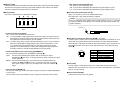
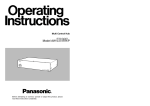
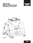
Live Switcher
Model No.
AW-SW350P
Live Switcher AW-SW350
POWER
WIPE PATTERN
TRANSITION TIME
ON
OFF
INCOM
WH1
WH2
WH3
SF0
SF1
SF2
YLW
CYN
GRN
MWR
INT
FRZ
MGT
RED
BLE
GEN-LOCK PHASE
SC
KEY AUTO
A
KEY
GAIN
CLIP
SOURCE
KEY AUTO
INV
LEVEL
H
AUTO TAKE
SETTING
SC FINE
IN5
COLOR
N
N/R
R
FMEM
FRZ
MIX
A
WIPE
5
1
2
3
4
FMEM
BLACK
COLOR
BAR
AUTO TAKE
B
B
Before attempting to connect, operate or adjust this product, please
read these instructions completely.
CAUTION
RISK OF ELECTRIC SHOCK
DO NOT OPEN
CAUTION: TO REDUCE THE RISK OF ELECTRIC SHOCK,
DO NOT REMOVE COVER (OR BACK).
NO USER SERVICEABLE PARTS INSIDE.
REFER TO SERVICING TO QUALIFIED SERVICE PERSONNEL.
The lightning flash with arrowhead symbol, within an equilateral triangle,
is intended to alert the user to the presence of uninsulated “dangerous
voltage” within the product’s enclosure that may be of sufficient
magnitude to constitute a risk of electric shock to persons.
The exclamation point within an equilateral triangle is intended to alert the
user to the presence of important operating and maintenance (service)
instructions in the literature accompanying the appliance.
FCC Note:
This device complies with Part 15 of the FCC Rules. To assure continued
compliance follow the attached installation instructions and do not make any
unauthorized modifications.
This equipment has been tested and found to comply with the limits for a class A
digital device, pursuant to Part 15 of the FCC Rules. These limits are designed to
provide reasonable protection against harmful interference when the equipment is
operated in a commercial environment. This equipment generates, uses, and can
radiate radio frequency energy and, if not installed and used in accordance with the
instruction manual, may cause harmful interference to radio communications.
Operation of this equipment in a residential area is likely to cause harmful
interference in which case the user will be required to correct the interference at his
own expense.
WARNING:
TO REDUCE THE RISK OF FIRE OR SHOCK HAZARD, DO NOT
EXPOSE THIS EQUIPMENT TO RAIN OR MOISTURE.
CAUTION:
TO REDUCE THE RISK OF FIRE OR SHOCK HAZARD AND ANNOYING
INTERFERENCE, USE THE RECOMMENDED ACCESSORIES ONLY.
CAUTION:
TO REDUCE THE RISK OF FIRE OR SHOCK HAZARD, REFER
CHANGE OF SWITCH SETTING INSIDE THE UNIT TO QUALIFIED
SERVICE PERSONNEL.
Note:
The rating plate (serial number plate is on the bottom of the unit.
The information marking of this product may be found on the bottom of the unit.
The serial number of this product may be found on the bottom of the unit.
You should note the serial number of this unit in the space provided and retain this book
as a permanent record of your purchase to aid identification in the event of theft.
Model No.
Serial No.
indicates safety information.
indicates safety information.
2
3
CONTENTS
WARNING/CAUTION FOR SAFETY
WARNING
WARNING/CAUTION FOR SAFETY ..................................................................................... 5
PREFACE .............................................................................................................................. 6
FEATURES ........................................................................................................................... 6
PRECAUTIONS ..................................................................................................................... 7
MAJOR OPERATING CONTROLS AND THEIR FUNCTIONS ............................................ 8
• Refer all servicing to qualified personnel
To reduce the risk of electric shock, don't remove cover or back, unless you are a
qualified personnel. Refer all mountings, connections, servicing to qualified service
personnel.
• No water or moisture inside
Do not let water or moisture into the product, or expose it to moisture, to prevent a fire and
electric shock.
■TOP (CONTROL PANEL) ........................................................................................ 8
■REAR PANEL ........................................................................................................ 15
IMAGE TRANSFER FUNCTION ......................................................................................... 20
■FUNCTIONS .......................................................................................................... 20
• If you see smoke or smell an odor from the product, if water or other foreign matter gets
inside, if it is damaged by dropping, or if you find anything wrong with it, immediately stop
using it.
• Do not disassemble or modify the product to prevent a fire and electric shock.
■SPECIFICATIONS ................................................................................................. 21
■INSTALLING THE DEVICE DRIVER ..................................................................... 22
■INSTALLING THE APPLICATION PROGRAM ..................................................... 25
■OPERATION METHOD ......................................................................................... 27
CONNECTIONS .................................................................................................................. 32
CAUTION
• Do not drop the product, do not expose it to strong shock, or do not step on it, to prevent
a fire and injuries.
■CONNECTION WITHOUT EXTERNAL SYNCHRONIZATION ............................. 32
■CONNECTION FOR EXTERNAL SYNCHRONIZATION ...................................... 33
■CONNECTION TO PERSONAL COMPUTER ...................................................... 34
■EXAMPLE FOR THE CONNECTION
WITH PAN/TILT HEADS AND CONTROL PANEL ............. 36
RACK MOUNTING .............................................................................................................. 38
• Do not install the product at a place full of moisture and dust, which may cause a fire and
electric shock.
• Do not mount the Live Switcher on a closed rack or bookshelf. (Otherwise, heat will build
up inside and may cause a fire.)
• Keep the ventilation port open to secure good flow of air.
■RACK MOUNTING ................................................................................................ 38
INFORMATION RELATED TO SYSTEM UPGRADES ...................................................... 39
SPECIFICATIONS/STANDARD ACCESSORIES .............................................................. 40
■SPECIFICATIONS ................................................................................................. 40
■STANDARD ACCESSORIES ................................................................................ 41
4
5
PREFACE
The AW-SW350 has five video inputs, wipe, mix and key synthesis functions despite its
compact dimensions. Since it has a built-in frame synchronizer, it accepts the input of
asynchronous signals. Moreover, it enables systems to be configured using the black burst
signals which it outputs, and it supports external synchronization (or genlock) to external sync
signals as well. Its image transfer function enables the images and text created using a
personal computer to be captured in the switcher through its USB port. The switcher can be
used in the field because it operates on an external power supply (12 V DC) while its tally
outputs and intercom inputs/outputs permit easy system configuration.
• Image Transfer, Soft Keys and Linear Keys
Inside the switcher AW-SW350 has a 1-frame frame memory so that the images created
using a personal computer can be captured in this memory through the USB port. There
are nine different patterns for wipe, and one of three softness levels can be set. Text can
also be synthesized smoothly by performing linear key operations.
• External Power Supply
The switcher can be used both indoors and outdoors because it operates on an external
power supply of 12 V DC.
(However, it is not built rainproof or dripproof. Do not expose the switcher to rains or
moisture.)
• Tally and Intercom Provided
Five tally outputs and five intercom inputs and outputs are available so that the switcher
can be directly apply to conventional systems. (The switcher has its own intercom on the
panel.)
FEATURES
• Five Inputs Despite Compactness
The switcher has five composite video signal inputs. (Automatic termination. Loopthrough
output provided) It also has an S-terminal (4-pin), and can thus handle YC signals. Input 5
can be switched to the internal frame memory or vice versa by means of a switch. Internal
black or color signal (9 patterns) can be selected.
• Three Program Outputs, Preview Outputs Available
Effect outputs including two composite video outputs (BNC connectors) and one YC
signal output (S-terminal, 4-pin) are available, so it is easy to build a system with
monitors, VCRs, etc. The AW-SW350 also features the Preview output to confirm the next
operation. (Look Ahead Preview)
• Frame Synchronizer System and Genlock System Supported
The switcher contains a high-performance 10-bit frame synchronizer: this means that
asynchronous signals can be directly input to the input camera or other such device
without having to initiate genlock. Its inputs are equipped with a frame synchronizer
function so that its images are do not freeze even when the frames are switched.
Alternatively, the frame synchronizer can be turned off, genlock can be applied to a
camera or other such device, and the unit can be used as a wideband switcher with
minimal deterioration in image quality (resolution of 800 lines).
• Genlock
The switcher enables genlocking to the reference sync signal of an external device.
Furthermore, by using its BB output, the system can be upgraded using the
synchronization of the switcher as a reference.
PRECAUTIONS
• Handle with Care.
Do not drop the switcher, or expose it to strong shock or vibration. This is important to
prevent trouble and accidents.
• Operating temperature range 32F to 104F
Avoid using it in a cold place below 32F or a hot place above 104F because low or high
temperature will adversely affect the parts inside.
• Switch power off before cables connection or disconnection.
Be sure to switch power off before connecting or disconnecting the cables.
• Use at a Place Not Humid, Not Dusty.
Avoid using the switcher at a humid, dusty place because the internal parts are subject to
damage by moisture and dust.
• Care
Switch power off and wipe the switcher with a dry cloth. If it is difficult to remove the dirt,
dip a cloth into a diluted solution of kitchen detergent, squeeze it hard, and wipe the
product carefully.
Note
• Do not use benzine, paint thinner, or other volatile liquids.
• When using a chemical duster, carefully read the caution notes on its use.
6
7
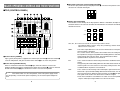
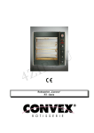
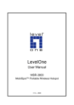
MAJOR OPERATING CONTROLS AND THEIR FUNCTIONS
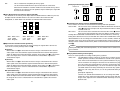
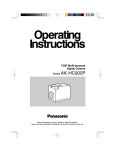
E Wipe Pattern Selection Switches [WIPE PATTERN]
To select a wipe pattern after pressing Wipe Switch y. One of the nine patterns can be
selected. The selected switch lights.
■TOP (CONTROL PANEL)
Live Switcher AW-SW350
POWER
WIPE PATTERN
TRANSITION TIME
ON
OFF
INCOM
WH1
WH2
WH3
SF0
SF1
SF2
YLW
CYN
GRN
MWR
INT
FRZ
AUTO TAKE
KEY AUTO
KEY
GAIN
MGT
RED
CLIP
BLE
SOURCE
GEN-LOCK PHASE
SC
SF0
SF1
SF2
MWR
INT
FRZ
INV
LEVEL
H
A
R Setting Switch [SETTING]
This functions as the shift key for the wipe patterns. While it is held down, the Wipe Pattern
Selection Switches can select the functions described below. The functions are indicated
with blue characters.
SETTING
SC FINE
KEY AUTO
IN5
COLOR
N
N/R
R
FMEM
FRZ
MIX
A
INV
WIPE
5
1
2
3
4
FMEM
BLACK
COLOR
BAR
AUTO TAKE
B
B
Q Power Indicator [POWER]
Lights (green) when power is supplied to DC Power Input Terminal L and Power Switch W
set to the ON position, and goes out when Power Switch W is set to the OFF position.
W Power Switch [POWER ON/OFF]
Power is switched on and Power Indicator Q lights when this switch is set to the ON
position, provided that power is supplied to DC Power Input Terminal L. Power is switched
off and Power Indicator Q goes out when the switch is set to the OFF position.
Caution
Even when the Power Switch is at the OFF position, some of the power supply circuits
are still operating. To turn off the power completely, set the external power adaptor to
OFF.
8
SF0, SF1, SF2: These are used to set the three wipe softness levels.
The minimum softness level is set by SF0 (a hard key), and the maximum
softness level is set by SF2.
MWR:
This makes it possible for the user to set the initial statuses of the panel
when the power is turned on.
First, set the statuses of the panel to be recorded. Once the setting has
been performed, keep pressing MWR while holding down the SETTING
switch until the nine switches go off. The recorded statuses will be
reproduced when the power is next turned on.
INT:
This is used to restore the initial settings which were established at the
factory.
Keep pressing INT while holding down the SETTING switch until the nine
switches go off. The same statuses as the factory setting statuses will be
established when the power is next turned on.
FRZ:
This is used to set the freezing of the Video Input 5 signal to ON or OFF.
When FRZ is pressed while holding down the SETTING switch, the Video
Input 5 signal is frozen. While the signal is frozen, the FRZ w LED lights.
This signal can be used as the source of the VIDEO IN 5 signal.
✽If the freeze function is used while the FS switch is in the OFF position,
only the Video Input 5 signal will be set to the FS ON status.
9
INV:
This is used to invert the polarity of the key signal.
Use the inversion mode when the input is black text on a white base.
When the INV function is used with VIDEO IN 5 selected for the key source
and with the FS switch in the OFF position, only the Video Input 5 signal will
be set to the FS ON status.
T Color Background Color Selector Switch [COLOR]
This functions as the shift key of the Wipe Pattern Selection Switches. While it is pressed,
the Wipe Pattern Selection Switches can select the color to be used for the color
background, as shown below. The functions are indicated with red characters.
WH1: White 100%
YLW: Yellow
MGT: Magenta
WH1
WH2
WH3
YLW
CYN
GRN
MGT
RED
BLE
WH2: White 90%
CYN: Cyan
RED: Red
WH3: White 80%
GRN: Green
BLE: Blue
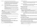
Y Wipe Direction Selection Switch [N/ N/R/ R]
To select one of the three directions in which to change the signals from A to B or vice
versa on the screen by moving Fader Lever i.
N (Normal):
When Fader Lever i is moved from A to B, the image is switched from the selected
A-bus signal to the selected B-bus signal in the direction of the black to white pattern
shown on Wipe Pattern Selection Switch. Similarly, when Fader Lever i is moved from
B to A, the image on the screen is switched from the selected B-bus signal to the
selected A-bus signal.
[Example] Selected wipe pattern
Fader lever
A
Normal (N)
Reverse (R)
Normal/Reverse (N/R)
A
B
B
A
A
B
B
A
A
B
A
B
B
A
B
U Transition Time Setting Controls [TRANSITION TIME]
These controls are used to set the transition time during auto fader operations.
AUTO TAKE: This is used to set the transition time of MIX or WIPE when the AUTO
TAKE u Switch has been pressed. Any transition time from 0 to about 10
seconds can be set.
KEY AUTO:
This is used to set the transition time when the KEY AUTO I Switch has
been pressed. Any transition time from 0 to about 5 seconds can be set.
Turning either control knob counterclockwise reduces the transition time; conversely,
turning them clockwise increases the transition time. When either control knob is turned
counterclockwise as far as it will go, the transition time is set to 0 seconds, and the cut
operation results. Even when external takes are performed using external switches, the
settings of these controls remain in force. (When a switch has been connected to EXT
TAKE H)
Caution
Before proceeding with auto fader operations, set the transition times in advance using
these controls.
N/R (Normal/Reverse):
When Fader Lever i is moved from A to B, the image is switched from the selected
A-bus signal to the selected B-bus signal in the direction of the black to white pattern
shown on Wipe Pattern Selection Switch. When Fader Lever i is moved from B to A,
the image on the screen is switched from the selected B-bus signal to the selected
A-bus signal.
I Key Synthesis Setting Controls [KEY]
These are used to perform the settings relating to key synthesis.
GAIN, CLIP:
The AW-SW350 features a linear key system for key synthesis to ensure
smooth synthesis, and these two controls are used to set the synthesis
levels when text and other data are to be synthesized with the key signals.
The CLIP control is for setting the reference level at which the key signals
are to be created, and signals above this level are synthesized. If noise is
present in the background images, set the CLIP level on the high side.
The GAIN control is for raising or lowering the level of the key signals.
Adjust it in such a way that the text, etc. can be synthesized cleanly and
clearly.
[Example of adjustment]
Turn the CLIP control counterclockwise as far as it will go and, while
viewing the screen, adjust the GAIN control to achieve clean and clear
images. Next, adjust the CLIP and GAIN controls alternately to set to the
optimum state.
10
11
R (Reverse):
When Fader Lever i is moved from A to B, the image is switched from the selected
A-bus signal to the selected B-bus signal in the direction of the white to black pattern
shown on Wipe Pattern Selection Switch. Similarly, when Fader Lever i is moved from
B to A, the image on the screen is switched from the selected B-bus signal to the
selected A-bus signal.
KEY AUTO:
SOURCE:
This switch is used to set the key synthesis to ON or OFF.
When it is pressed, it lights, and key synthesis is performed for the text, etc.
KEY AUTO U is used to set the transition time for the key synthesis. When
the switch is pressed again, it goes off, and the input signals used for the
key synthesis will be synthesized as they are with the base image but,
depending on the level of the input signals, it may not be possible to
achieve clean and clear images.
This selects whether to use the VIDEO IN 5 signal or image in the frame
memory as the source material for the key synthesis. In terms of the key
signals, use black base level signals, and provide a source with white
characters.
A source with color characters can also be synthesized with a black base
but, depending on the level of the character signals, it may not be possible
to achieve clean and clear images.
(By inverting the polarity of the key signals, images with a white base level
can also be synthesized. For details on key reversal, refer to SETTING R.)
Note
Follow the procedure below to keep the key synthesis on the PVW screen at the OFF
setting at all times.
1. Press both the SETTING Button R and COLOR Button T at the same time.
2. With the two buttons in step 1 held down, press the KEY AUTO Button.
The KEY AUTO Button lamp now lights.
To turn the key synthesis on the PVW screen back to the ON setting, repeat the same
steps. The KEY AUTO Button lamp will then go off.
O Intercom Jack [INCOM]
Connect an intercom headset to this terminal. Use the recommended headset (made by
Ashida Onkyo MT-12MFB-03).
P Intercom Volume [INCOM LEVEL]
To adjust the volume of the headset speaker connected to Intercom Jack O. Turning it
counterclockwise decreases the volume, and turning it clockwise increases it.
{ Genlock Phase Controls [GEN-LOCK PHASE]
Connect a signal generator or other such instrument to GLIN/BBOUT D, and use these
controls to adjust the phase when genlock is to be initiated. These controls need not be
adjusted when genlock is not going to be initiated.
H:
This is used to adjust the horizontal sync phase.
SC:
This is used to adjust the subcarrier phase coarsely.
SC FINE: This is used to adjust the subcarrier phase finely.
12
Adjusting the horizontal phase:
Monitor the waveforms of the genlock signal (black burst signal) and video
signal output using a dual-trace oscilloscope (or waveform monitor), and adjust
the H Control in such a way that the horizontal phase is aligned.
Adjusting the subcarrier phase:
Select the color bars of the switcher. Using the signal generator as a reference,
adjust the SC Control and SC FINE Control to align the color phase. A more
accurate adjustment can be achieved using a vectorscope.
} A-Bus Input Selection Switches
To select A-bus video signals. When a switch is pressed, it lights and indicates that the
corresponding signal is selected.
q B-Bus Input Selection Switches
These are used to select the B-bus video signals. When a switch is pressed, it lights to
indicate that the corresponding signal is selected.
Depending on the operation mode, the switches may light with full or half brightness.
Full brightness: When the selected input is being output to PGM OUT.
Half brightness: When the switch is selected but the selected input is not being output
to PGM OUT.
[Example] When the Fader Lever is at the A-bus side, the A-bus signals are output so that
the A-Bus Input Selection Switches will light with full birghtness, but the B-bus
signals are not output so that B-Bus Input Selection Switches will light with half
brightness.
w Freeze indicator [FRZ]
This LED lights to indicates that the VIDEO IN 5 signal is frozen. Bear in mind that since
the image remains frozen while it is lighted, the switcher output will not change even when
the input signal has changed.
e Input 5/FMEM Selector Switch [FMEM]
This is used to select the signal which has been input to VIDEO IN 5 or the internal frame
memory. When the switcher is used for the first time and the frame memory has been
selected, the factory setting screen is output. By transferring image data from a personal
computer to the frame memory, the images and text created by the user can be output. For
details, refer to the page on which image transfer is described.
r BLACK/COLOR/BAR Selector Switch [BLACK/COLOR/BAR]
This is used to select BLACK (black level signal), COLOR (color background) or BAR (color
bar). When COLOR is selected, one of nine colors can be selected. For details on how to
select the color, refer to the section on “T Color Background Color Selector Switch
[COLOR]”.
A 100% white signal is output at the factory setting.
13
t Mix Switch [MIX]
Press it to switch the signal selected with A-Bus Input Selection Switch } to the signal
selected with B-Bus Input Selection Switch q or vice versa by the mix effect. The switch
lights when MIX is selected.
y Wipe Switch [WIPE]
Press it to switch the signal selected with A-Bus Input Selection Switch } to the signal
selected with B-Bus Input Selection Switch q or vice versa by the wipe effect. The switch
lights when WIPE is selected.
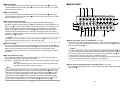
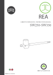
■REAR PANEL
BBOUT
GLIN
/BBOUT
PVW
OUT
PGM OUT
1
2
5
4
VIDEO
3
2
1
IN
u Auto Take Switch [AUTO TAKE]
This switch is used for automatically wiping or mixing instead of performing these
operations manually using the Fader Lever i. This switch becomes operational when the
Fader Lever i is set all the way toward the A or B side, and when it is pressed once, the
wipe or mix operation is performed automatically. The transition time for switching the
signals can be adjusted using the AUTO TAKE U control. While the signals are being
switched, the AUTO TAKE switch lights, and it goes off when the signals are switched
completely. During an auto take operation, no manual operations will be performed even if
the Fader Lever i is moved.
Caution
In using the Auto Take function, be sure to move Fader Lever i all the way to A or B.
Auto Take will not work unless the lever is fully moved to A or B.
i Fader Lever [A/B]
This lever is used to switch the signal selected with A-Bus Input Selection Switch } to the
signal selected with B-Bus Input Selection Switch q or vice versa by the wipe or mix effect.
When the lever is moved from A to B, the video signal is also switched from A to B
accordingly. Similarly, when the lever is moved from B to A, the video signal is switched
from B to A.
o Bus Tally Indicators [A], [B]
These indicate the output statuses of the A-bus and B-bus. The [A] or [B] LED lights to
indicate that A-bus or B-bus signals are being output.
[Examples] • [A] lights when the Fader Lever is at the A side since only the A-bus signals
are output.
• Both [A] and [B] light when the Fader Lever is between the A and B sides
since both A-bus and B-bus signals are output.
Note
Bus control based on the flip-flop system is enabled by changing the setting of the bus
selector switch [BUS A/B /F.F.]R which is one of the Setup Switches K. Under the flipflop system, the signals selected by the A-Bus Input Selection Switches } are always
selected as the program (PGM) video signals, and the signals selected by the B-Bus
Input Selection Switches q are always selected as the preview (PVW) video signals.
Furthermore, the PGM signals can be replaced with the PVW signals or vice versa by
means of bus switching using the AUTO TAKE Switch u and Fader Lever i.
14
75Ω
AUTO
TALLY & INCOM
5
4
3
2
1
OUT
DC 12V IN
SET UP
1 2 3 4
USB
EXT
TAKE
Y / C IN
PGM
Y/C
OUT
5
GND
4
3
2
1
p Video Signal Input Jacks 1 to 5 [VIDEO IN 1, 2, 3, 4, 5]
These jacks are to input composite video signals. (1 Vp-p, 75-ohm auto-terminated)
There are 5 input jacks corresponding to A-Bus Input Selection Switches } and B-Bus
Input Selection Switches q.
Caution
If a BNC coaxial cable is connected to Video Signal Loopthrough Output Jack [, the
75-ohm termination is automatically released. Do not connect a BNC coaxial cable to
any of these jacks in case of connecting YC signals to Y/C Signal Input Jack ]. Use
either composite signals or YC signals as video input signals.
Furthermore, when unstable video signals from a VHS format VCR, DVD player or other
device have been input, the frame synchronizer may malfunction.
[ Video Signal Loopthrough Output Jacks [VIDEO OUT 1, 2, 3, 4, 5]
These loopthrough output jacks are for the composite video signals input to Video Signal
Input Jacks p.
15
] Y/C Signal Input Jacks [Y/C IN 1, 2, 3, 4, 5]
Connect YC signals to these jacks in using them as video input signals.
Caution
Do not connect a BNC coaxial cable to Video Signal Input Jack p in case of connecting
YC signals to Y/C Signal Input Jack ]. Use either composite signals or YC signals as
video input signals.
4
2
3
1
Pin No.
1
2
3
4
Signal
Y GND
C GND
Y
C
A Video Output Connectors [PGM OUT 1, 2]
Two sets of composite signals (BNC) consisting of the switcher's main output together with
the wipe, mix, key or other effects added are output from these output jacks.
S Preview Output Connector [PVW OUT]
When the switcher is used for live applications, this connector enables the next operation to
be previewed. (LOOK AHEAD PREVIEW)
• While the Fader Lever is at the A-bus side and A-bus signals are output, the B-bus signals
are output to the PVW OUT Connector, and the images can be previewed.
• When the PGM OUT Connectors are in the key OFF status, the PVW OUT Connector is
set to the key ON status and the key synthesis status can be previewed.
The table below shows the correlation between the program output and preview output
statuses.
PGM OUT
PVW OUT
Bus selection
A-bus selected
B-bus selected
B-bus output
A-bus output
D Genlock Input/BB Output Connector [GLIN/BBOUT]
In compliance with the setting of the SETUP switch K, either the genlock input or BB
output is selected.
Genlock input: To apply genlock to the switcher, connect this signal to the signal generator
or other device.
BB output:
At this position, the BB sync signal is output to apply genlock to a camera or
other input device by synchronizing it to the switcher. In this case, the same
signal as BBOUT F is output.
F Black Burst Signal Output Connector [BBOUT]
Used to externally synchronize a input device connected to the Live Switcher. When
externally synchronizing two or more devices, distribute the black burst output to them
using a video distributor (VDA).
G Y/C Video Output Connector [PGM Y/C OUT]
This connector delivers the Y/C signal video output which has the same function as the
video output signal A.
Caution
Due to what is involved in the signal processing, the Y/C video output G has a phase
which is delayed by 1 line compared with the composite video output A.
H Auto Take External Input Jack [EXT TAKE]
Use it for external auto take by applying a contact input. The operation is the same as when
using Auto Take Switch u and Key Auto Switch I.
✽Use an M3.5 stereo single head plug for connection with this unit.
Connect the switches as shown below.
Key ON/OFF
Key ON
Key OFF
Key OFF
Key ON
AUTO TAKE
KEY AUTO
16
17
J USB port [USB]
Connect one end of the USB cable to this port and the other end to the personal computer
to transfer the image data created by the personal computer to this switcher. For details,
refer to the page on which image transfer is described.
K Setup switches
These are used to perform the following four settings.
ON
BBOUT
3-wire
type
A/B
OFF
GLIN
4-wire
type
F.F.
GLIN INCOM
/BBOUT
BUS
FS
QFrame Sync Switch [FS ON/FF]
This sets the frame synchronizer to ON or OFF.
ON: The asynchronous 5 input signal can be connected. A delay of up to one frame is
generated in the switcher output. Due to what is involved in the signal processing,
the signal band is narrower than at the OFF position.
OFF: The input signal source must be synchronized with the system. Use the switcher's
black burst signal output to apply genlock to the camera or other device. In this
case, perform the phase (horizontal phase, color phase) adjustments for the
genlock at the connected device. In this mode, analog processing is performed
internally, and there is virtually no deterioration in the image quality.
WGenlock input/Black burst output setting [GLIN/BBOUT]
This sets the input or output for the GLIN/BBOUT Connector D.
GLIN:
Set here when genlocking the switcher with an external sync signal.
GLIN/BBOUT D now serves as an input connector, and an external sync signal
can be connected.
BBOUT: Set here when configuring a system based on the synchronization to the
switcher. GLIN/BBOUT D now serves as an output connector, and a black
burst signal is output. In this case, the output is the same as the BBOUT F
signal.
EIntercom Switch [INCOM 3/4]
The 3-wire or 4-wire type can be selected by setting the switch to the position appropriate
to your system.
(Set the switch to the 3-wire position if you are using the WV-RC700A or WV-RC550.)
18
RBus Selector Switch [BUS A/B /F.F.]
This selects the bus switching system.
A/B: Set here when undertaking bus operations using the A/B bus system.
F.F.: Set here when undertaking bus operations using the flip-flop system.
L DC Power Input Terminal [DC 12V IN]
Apply 12-V DC power. (Use the AC adaptor AW-PS505.)
✽The AW-CA4T1 cable (sold separately) is required.
Caution
If you are using other power supply, make sure that it outputs 12 V DC, 2.5 A or more.
The plug has GND on the inside and +12 V outside. (Be careful of the positive and
negative polarities.)
Positive (+)
Negative (–)
:Tally/Intercom Connectors [TALLY & INCOM 1, 2, 3, 4, 5]
Use these jacks to connect the Live Switcher to the tally/intercom connectors on a camera
control unit, for example, WV-RC700A or WV-RC550, for tally control and intercom
communication. Tally control is based on open collector output. These connectors are
compatible with either the 3-wire or 4-wire type of intercoms, selectable with Setup
Switch K.
6
5
4
3
2
1
Pin No.
1
2
3
4
5
6
Signal
MIC+
MIC–/COMMON
PHONE+
PHONE–/COMMON
TALLY
GND
a Cord Clamp
Used to clamp the cable connected to the DC power input terminal to prevent its
disconnection. Once remove the screw, pass the cable, and retighten the screw till the
cable is securely clamped.
s Ground Terminal [GND]
Connect this to the system frame ground.
19
IMAGE TRANSFER FUNCTION
The AW-SW350 Live Switcher comes with a function for transferring images from the host
computer using the USB (Universal Serial Bus). The image data transferred from the host
computer can be used as the key input signals or main input signals of the AW-SW350.
When the image transfer function is to be used for the first time, the dedicated device driver
and application program must be installed in the host computer. They can be installed from
the CD-ROM that is supplied with the AW-SW350. For details on how to install them, refer to
“Installing the Device Driver” and “Installing the Application Program”.
■SPECIFICATIONS
In order for the host computer to run the USB image transfer program used with the
AW-SW350, it must satisfy the following system requirements.
Processor
Pentium III, 1 GHz or up recommended
RAM
128 MB or more
Free hard drive memory
50 MB or more
Operating system
Windows 98 Second Edition (SE), Windows Me,
Windows 2000, Windows XP
USB port
USB Version 1.1 or up
CD-ROM drive
Essential
■FUNCTIONS
The USB image transfer program used with the AW-SW350 contains the following
functions.
• Frame memory image transfer function (RAM)
• Flash memory image transfer function (ROM)
• Image cutout position designation function
• Image start position designation function
For more details on how to use these functions, refer to “Operation Method”.
20
Image files in two formats, the bitmap format (bmp) and JPEG format (jpg, jpeg), can be
used with the USB image transfer program for the AW-SW350. Also required separately
when using the image transfer function is the A-B type USB cable for connecting the host
computer with the AW-SW350.
Caution
More time is required to transfer the images if the performance of the personal
computer is low-level. The function will not work with versions of Windows that
are not recommended (Windows 3.1, Windows 95, Windows 98, Windows NT4.0).
Pentium is a registered trademark of Intel Corporation.
Windows, Windows 98, Windows Me, Windows 2000 and Windows XP are
registered trademarks of Microsoft Corporation.
21
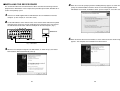
■INSTALLING THE DEVICE DRIVER
This section describes how to install the device driver used with the USB image transfer
program for the AW-SW350. In the example of the procedure given below, Windows XP is
used as the operating system.
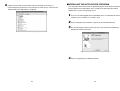
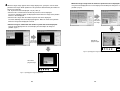
4 When the screen for specifying the driver loading directory appears as shown in Fig.3,
specify the \DRIVER folder of the drive where the CD-ROM supplied with the
AW-SW350 was inserted, and load the driver. (In this example, E: is the drive used.)
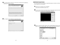
1 Insert the CD-ROM supplied with the AW-SW350 in the CD-ROM drive of the host
computer. (In this example, E: is the drive used.)
2 Set the AW-SW350's Power Switch to ON, check that the Power Indicator has lighted,
and connect one end of the A-B type USB cable to the USB port on the rear panel of
the AW-SW350 and the other end to the USB port on the host computer. (Fig.1)
BBOUT
GLIN
/BBOUT
PVW
OUT
PGM OUT
1
2
5
4
VIDEO
3
2
1
IN
4
3
2
Windows PC
75Ω
AUTO
TALLY & INCOM
5
1
Fig.3 Driver specification screen
OUT
DC 12V IN
SET UP
1 2 3 4
GND
USB
EXT
TAKE
Y / C IN
PGM
Y/C
OUT
5
4
3
2
1
5 When the device driver has been loaded, a screen similar to the one shown in Fig.4
AW-SW350 Rear
USB cable
appears. This completes the installation of the device driver.
Fig.1 Connections
3 When the host computer recognizes the AW-SW350, as shown in Fig.2, the Found
New Hardware Wizard automatically starts up.
Fig.4 Driver loading completion screen
Fig.2 Found New Hardware Wizard start screen
22
23
6 In order to confirm that the device driver has been installed successfully, it is
recommended that you open the Device manager as shown in Fig.5, and check that
“AW-SW USB Device:AW-SW350” is displayed.
■INSTALLING THE APPLICATION PROGRAM
This section describes how to install the application program used with the USB image
transfer program for the AW-SW350. In the example of the procedure given below,
Windows XP is used as the operating system.
1 Insert the CD-ROM supplied with the AW-SW350 in the CD-ROM drive of the host
computer. (In this example, E: is the drive used.)
2 Run the “Microsoft .Net Framework” setup file (E:\JPN\DOTNETFX.EXE).
3 The installer program shown in Fig.6 now starts. Proceed with the installation by
following the installer instructions.
Fig.5 Device manager screen
Fig.6 Microsoft .Net Framework installer start screen
4 Run the setup program (E:\JPN\SETUP.EXE).
24
25
5 The installer program shown in Fig.7 now starts. Proceed with the installation by
following the installer instructions.
■OPERATION METHOD
This section describes how to operate the application program used with the USB image
transfer program for the AW-SW350.
1 Connect the host computer to the AW-SW350.
(Check that the AW-SW350's power is on.)
2 The main screen shown in Fig.9 appears when the application program used with the
USB image transfer program for the AW-SW350 is started up.
Fig.7 Application program installer start screen
6 This completes the installation of the application program.
Fig.9 Application program main screen
3 When the “Open File” button is clicked, the file selection dialog box shown in Fig.10
appears. Select the image file (BMP, JPG or JPEG) to be transferred, and click “OK”.
Fig.8 Application program installation completion screen
Fig.10 File selection dialog box
26
27
4 When the target image appears in the image display area, specify the start or cutout
position of the image. Which position is to be specified is determined by the number of
pixels in the image file.
• No. of pixels that can be displayed: 720 (H) x 487 (V)
• When the file is smaller than the number of pixels that can be displayed:
The spaces around the image are displayed in black. Move the image to the position
where it is to be displayed.
• When the file is larger than the number of pixels that can be displayed:
The frame outlining what can be displayed appears. Move the frame to the position
where the image to be displayed is framed.
<When the image is larger than the number of pixels that can be displayed>
Drag the frame displayed in the screen display area and drop it to change the cutout
position. (Fig.12)
specify the
cutout position
of the image
<When the image is smaller than the number of pixels that can be displayed>
Drag the image displayed in the screen display area and drop it to change its
position. (Fig.11)
specify the
start position
of the image
AW-SW350
program output
Fig.12 Specifying the image cutout position
AW-SW350
program output
Fig.11 Specifying the image start position
28
29
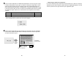
5 Click the “RAM” radio button or “RAM+ROM” radio button to select the type of memory
in which the data will be saved. (Fig.13) If “RAM” is selected, the image data is saved
only in the frame memory and so it cannot be used after the AW-SW350 power has
been turned off and back on again. If “RAM+ROM” is selected, the image data is saved
in the flash memory and so it can be used after the AW-SW350 power has been turned
off and back on again. However, the actual transfer takes longer than when “RAM” is
selected.
RAM
RAM+ROM
Status after power has been turned off and back on again
Transfer time
Transferred image data cannot be used
Approx. 10 sec.
Transferred image data can be used
Approx. 60 sec.
— When images could not be transferred —
If an error resulted or images could not be transferred because a cable was connected or
disconnected, turn off the switcher's power and exit the application program. Then turn the
switcher's power back on again and start up the application again.
✽The transfer times given in the above table are approximations only. The actual time
taken will depend on the performance of the host computer.
Fig.13 Memory selection
6 Click the “Write USB” button to start transferring the image data. After the completion
of the transfer, monitor the AW-SW350's PGM output and check that the image data
has been transferred. (Fig.14)
AW-SW350
program output
Click the
button
Fig.14 PGM check
30
31
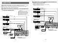
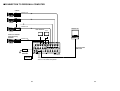
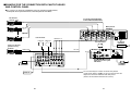
■CONNECTION FOR EXTERNAL SYNCHRONIZATION
(Frame Synchronizer OFF)
CONNECTIONS
●For installation and connection, be sure to ask the store where you purchased the product.
●Before making any connection, switch off all the components of the system.
●Carefully read the manuals for the individual devices connected to the Live Switcher.
●Use coaxial cable to connect video and genlock signals.
●Adjust the horizontal and color phases of the cameras.
(Read the manual for the camera.)
Camera
VIDEO OUT
■CONNECTION WITHOUT EXTERNAL SYNCHRONIZATION
(Frame Synchronizer ON)
E600
Convertible Camera AW —
Caution
When unstable video signals,
such as those from a VCR, are
being used for the input signals,
the internal frame synchronizer
may not operate correctly.
G/L IN
E600
Convertible Camera AW —
VIDEO OUT
Camera
VIDEO OUT
E600
Convertible Camera AW —
Color monitors
G/L IN
PVW OUT PGM OUT
E600
Convertible Camera AW —
Camera or character
generator for key
synthesis
E600
Convertible Camera AW —
E600
Convertible Camera AW —
VIDEO OUT
G/L IN
VIDEO OUT
BBOUT
GLIN
/BBOUT
OUTPUT
Color monitors
PVW
OUT
PGM OUT
2
1
5
4
VIDEO
3
2
1
IN
E600
Convertible Camera AW —
PVW OUT PGM OUT
5
INPUT
A
4
1
1
2
2
DC 12V IN
SET UP
1 2 3 4
2
1
USB
EXT
TAKE
Y / C IN
PGM
Y/C
OUT
THR SEP
75Ω
HI-Z
B
3
3
AC adaptor
AW-PS505
GND
5
4
3
2
1
AW-SW350
VIDEO OUT
Video distributor
WJ-300C
E600
Convertible Camera AW —
BBOUT
GLIN
/BBOUT
PVW
OUT
PGM OUT
2
1
5
4
VIDEO
3
2
QFS switch [OFF]
WGLIN/BBOUT switch [BBOUT]
VCR, etc.
1
IN
Signal
generator
✽When a signal
generator is used to
generate the
reference signals
for the system
3
OUT
OUTPUT A OUTPUT B
INPUT
Camera or character
generator for key
synthesis
75Ω
AUTO
TALLY & INCOM
75Ω
AUTO
TALLY & INCOM
5
4
3
2
1
OUT
DC 12V IN
SET UP
1 2 3 4
AC adaptor
AW-PS505
GND
USB
EXT
TAKE
Y / C IN
PGM
Y/C
OUT
5
4
3
2
1
AW-SW350
QFS switch [ON]
WGLIN/BBOUT switch [GLIN]
VCR, etc.
32
33
■CONNECTION TO PERSONAL COMPUTER
Camera
VIDEO OUT
E600
Convertible Camera AW —
E600
Convertible Camera AW —
VIDEO OUT
Windows PC
Color monitors
E600
Convertible Camera AW —
OUT
Camera or character
generator for key
synthesis
VIDEO OUT
E600
Convertible Camera AW —
BBOUT
GLIN
/BBOUT
PVW
OUT
PGM OUT
2
1
5
4
VIDEO
3
2
1
IN
75Ω
AUTO
TALLY & INCOM
5
4
3
2
1
OUT
DC 12V IN
SET UP
1 2 3 4
AC adaptor
AW-PS505
GND
USB
EXT
TAKE
Y / C IN
PGM
Y/C
OUT
5
4
3
2
Connected with
USB cable
1
AW-SW350
VCR, etc.
These switches operate whether the FS
switch is in the ON or OFF position.
34
35
■EXAMPLE FOR THE CONNECTION WITH PAN/TILT HEADS
AND CONTROL PANEL
●The cameras can be locally controlled by using the pan/tilt head AW-PH300A,
multi-hybrid control panel AW-RP505, and multi-port hub AW-HB505.
Pan/tilt head
cameras 1 to 4
To pan/tilt head AW-PH300A,
Camera AW-E300/E600/E800A
E600
Convertible Camera AW —
Multi-port hub
AW-HB505
E600
Convertible Camera AW —
TO C A M E R A PA M / T I LT H E A D
VIDEO
IN
VIDEO
IN
PAM/TILT
CONTROL OUT
G/L
OUT
S-VIDEO OUT
G/L
OUT
VIDEO OUT
Color monitors
PVW OUT PGM OUT
E600
Convertible Camera AW —
VIDEO
IN
PAM/TILT
CONTROL OUT
S-VIDEO OUT
G/L
OUT
VIDEO OUT
S-VIDEO OUT
VIDEO OUT
PGM OUT
1
2
5
4
VIDEO
3
CAMERA
CONTROL OUT
CAMERA
CONTROL OUT
3
2
1
DC12V
IN
SEE MANUAL
2
AC adaptor
AW-PS505
Preview monitor
G / L IN
PREVIEW MONITOR OUT
M U LT I
PORT
DC12V IN
HUB
AUX CONTROL IN
1
PA N / T I LT
CAMERA
CONTROL OUT CONTROL OUT
G/L OUT
PREVIEW IN
5
4
3
2
1
75Ω
AUTO
TALLY & INCOM
3
CAMERA
CONTROL IN
TALLY
2
IN
4
G/L
IN
VIDEO OUT
CAMERA
CONTROL OUT
4
TD
5
VIDEO OUT
CAMERA
CONTROL OUT
G/L IN
PVW
OUT
S-VIDEO OUT
G/L
OUT
5
G/L OUT
G/L IN
GLIN
/BBOUT
S-VIDEO OUT
G/L
OUT
PAM/TILT
CONTROL IN
PAM/TILT
CONTROL OUT
CAMERA
CONTROL OUT
VIDEO OUT 1-4
VIDEO OUT
BBOUT
VIDEO
IN
PAM/TILT
CONTROL OUT
VIDEO IN 1-4
E600
Convertible Camera AW —
Camera or character
generator for key
synthesis
TO C O N T R O L PA N E L
PREVIEW OUT
VIDEO
IN
PAM/TILT
CONTROL OUT
1
OUT
DC 12V IN
SET UP
1 2 3 4
AC adaptor
AW-PS505
GND
USB
EXT
TAKE
Multi-hybrid control panel
AW-RP505
Y / C IN
PGM
Y/C
OUT
5
4
3
2
AC adaptor
AW-PS301
1
AW-SW350
The FS switch may be in either the ON or OFF position.
If high picture quality is desired, set the FS switch to OFF and
adjust each camera for horizontal and color phases.
(Refer to the instruction manual for the camera.)
VCR, etc.
36
37
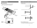
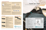
RACK MOUNTING
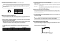
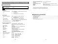
INFORMATION RELATED TO SYSTEM UPGRADES
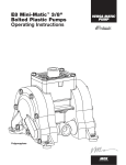
■RACK MOUNTING
(1) Switcher phases
1) Video signal output phase (frame synchronizer is OFF)
●Do not mount the Live Switcher on a closed rack or bookshelf.
(Otherwise, heat will build up inside and may cause a fire.)
●Keep the ventilation port open to secure good flow of air.
Video signal input phase
Video signal output phase
POWE
Approx. 50nS
R
ON
OF
F
SF
INC
OM
GE
H
N-LO
CK
SC
LEVE
L
WH
1
WIPE
0
WH
YL W
MW
R
SF
2
PH
AS
SC E
WH
SF
RED
FR
FIN
E
3
2
AUTO
GRN
Z
KEY
TIM
E
AUTO
INV
CO
1
LO
GA
IN
FR
Z
KE
Y
R
A
2
3
TR
AN
SIT
ION
TAK
E
BLE
SETT
ING
BB phase
PATT
ER
N
1
CYN
INT
MG
T
CL
IP
N/ N
R
R
SOUR
IN
5
Rack mounting parts
A
CE
KEY
FM
EM
4
AU
2) Video signal input phase (frame synchronizer is ON)
TO
5
B
FM
EM
MIX
BL
CO ACK
BA LOR
R
WI
PE
AU
TO
TAK
E
B
Input phase range
max. of 1 frame
BB phase
Connecting
plate
Mounting
screw
Mounting
screw
3) Genlock adjustment range
Approx.
1µS
Approx. 3µS
BB phase
Holes for
connecting plate
(Bottom)
(2) TALLY & INCOM connectors
Use a Mini DIN type 6-pin connector for tally and intercom connections.
(e.g.) TCP8060-01-520 manufactured by Hosiden Corporation
38
39
SPECIFICATIONS/STANDARD ACCESSORIES
■SPECIFICATIONS
Power supply:
Power consumption:
12 V DC (+10.8 ~ 16.0V)
16 W
indicates safety information.
Video Inputs
Composite video signal:
Y/C:
Video Outputs
Composite video output:
Y/C:
Preview output:
Black burst signal:
Signal loopthrough output:
VBS: 1.0 V[p-p]/75 Ω!5 (BNC connector, automatic
termination)
Y:
1.0 V[p-p]/75 Ω
C:
0.286 V[p-p]/75 Ω!5 (S connector)
VBS: 1.0 V[p-p]/75 Ω!2 (BNC connector)
Y:
1.0 V[p-p]/75 Ω!1
C:
0.286 V[p-p]/75 Ω!1 (S connector)
VBS: 1.0 V[p-p]/75 Ω!1 (BNC connector)
BBS: Sync: 0.286 V[p-p], C: 0.286 V[p-p] burst level/
75 Ω!1 (BNC connector)
1 each (BNC connector)
Operating temperature range:
Humidity:
Dimensions (W!H!D):
Weight:
Finish:
32˚F to 104˚F (0˚C to 40˚C)
30% to 90%
8-1/4”!3-7/16”!6-15/16” (210!86!176 mm)
Approx. 4.9 lb (2.2 kg)
AV ivory painting (Munsell 7.9Y6.8/0.8 or close to it)
Weight and dimensions indicated are approximate.
Specifications are subject to change without notice.
■STANDARD ACCESSORIES
Tally/intercom connector .............................................................................................. 5 pcs.
Rack mounting parts ..................................................................................................... 2 pcs.
Connecting plate ............................................................................................................ 1 pc.
Mounting screws ............................................................................................................ 1 set
Image transfer program setup CD .................................................................................. 1 pc.
Functions and Performance
Frame synchronizer:
10 bit quantization, 13.5MHz sampling
Mounted to each channel of VIDEO IN 1 to 5.
Wipe patterns:
9 patterns
Wipe directions:
3 directions (normal, reverse, normal/reverse)
Mix:
Cross fader
Auto take:
Wipe, Mix (time adjustable)
Key synthesis:
Self Key, Linear Key
Intercom:
1 to 5 (6-pin connector, 3/4 wire selectable),
Intercom jack (M6 jack)
Tally control:
1 to 5 (open collector output)
Color bar:
Internal (SMPTE, Black/Color selectable)
White and black signals:
Internal
Frequency response:
FS ON:
6.0MHz +1 dB, –3dB
FS OFF: 10.0MHz +1 dB, –3dB
S/N:
FS ON:
More than 58 dB
FS OFF: More than 65 dB
DG/DP:
FS ON:
±2°, ±2%
FS OFF: ±1.5°, ±1.5%
40
41
Memo
42
43
PANASONIC BROADCAST & TELEVISION SYSTEMS COMPANY
DIVISION OF MATSUSHITA ELECTRIC CORPORATION OF AMERICA
Executive Office:
3330 Cahuenga Blvd W., Los Angeles, CA 90068 (323) 436-3500
EASTERN ZONE:
One Panasonic Way 4E-7, Secaucus, NJ 07094 (201) 348-7621
Southeast Region:
1225 Northbrook Parkway, Ste 1-160, Suwanee, GA 30024 (770) 338-6835
Central Region:
1707 N Randall Road E1-C-1, Elgin, IL 60123 (847) 468-5200
WESTERN ZONE:
3330 Cahuenga Blvd W., Los Angeles, CA 90068 (323) 436-3500
Government Marketing Department:
52 West Gude Drive, Rockville, MD 20850 (301) 738-3840
Broadcast PARTS INFORMATION & ORDERING:
9:00 a.m.–5:00 p.m. (EST) (800) 334-4881/24 Hr. Fax (800) 334-4880
Emergency after hour parts orders (800) 334-4881
TECHNICAL SUPPORT:
Emergency 24 Hour Service (800) 222-0741
Panasonic Canada Inc.
5770 Ambler Drive, Mississauga, Ontario L4W 2T3 (905) 624-5010
Panasonic de Mexico S.A. de C.V.
Av angel Urraza Num. 1209 Col. de Valle 03100 Mexico, D.F. (52) 1 951 2127
Panasonic Sales Company
Division of Matsushita Electric of Puerto Rico Inc.
San Gabriel Industrial Park, 65th Infantry Ave., Km. 9.5, Carolina, Puerto Rico 00630 (787) 750-4300
Printed in Japan
VQT0D92
F0303S0 D
P