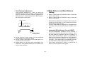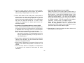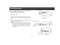
1
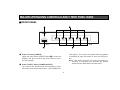
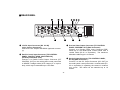
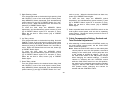
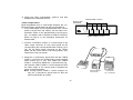
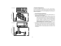
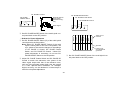
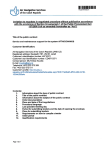
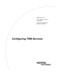
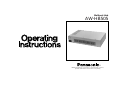
Multiport Hub AW-HB505 Before attempting to connect or operate this product, please read these instructions completely. CAUTION RISK OF ELECTRIC SHOCK DO NOT OPEN CAUTION: TO REDUCE THE RISK OF ELECTRIC SHOCK, DO NOT REMOVE COVER (OR BACK). NO USER SERVICEABLE PARTS INSIDE. REFER SERVICING TO QUALIFIED SERVICE PERSONNEL. For U.S.A Warning: This equipment generates and uses radio frequency energy and if not installed and used properly, i.e., in strict accordance with the instruction manual, may cause harmful interference to radio communications. It has been tested and found to comply with the limits for a Class A computing device pursuant to Subpart J of Part 15 of FCC Rules, which are designed to provide reasonable protection against such interference when operated in a commercial environment. For CANADA SA 1965 The lightning flash with arrowhead symbol, within an equilateral triangle, is intended to alert the user to the presence of uninsulated "dangerous voltage" within the product's enclosure that may be of sufficient magnitude to constitute a risk of electric shock to persons. The exclamation point within an equilateral triangle is intended to alert the user to the presence of important operating and maintenance (servicing) instructions in the literature accompanying the appliance. SA 1966 This digital apparatus does not exceed the Class A limits for radio noise emissions from digital apparatus set out in the Radio Interference Regulations of the Canadian Department of Communications. The serial number of this product may be found on the bottom of the unit. You should note the serial number of this unit in the space provided and retain this book as a permanent record of your purchase to aid identification in the event of theft. Model No. Serial No. WARNING: TO PREVENT FIRE OR ELECTRIC SHOCK HAZARD, DO NOT EXPOSE THIS APPLIANCE TO RAIN OR MOISTURE. CONTENTS FEATURES .................................................................................................................................................................................. 2 PRECAUTIONS ........................................................................................................................................................................... 3 MAJOR OPERATING CONTROLS AND THEIR FUNCTIONS ..................................................................................................... 4 ■ FRONT PANEL .................................................................................................................................................................... 4 ■ REAR PANEL ........................................................................................................................................................................ 6 INSTALLATION OF PAN/TILT HEAD ........................................................................................................................................... 8 CONNECTION ............................................................................................................................................................................. 11 OPERATION ................................................................................................................................................................................ 15 RACK MOUNTING ...................................................................................................................................................................... 23 SPECIFICATIONS ........................................................................................................................................................................ 24 ACCESORIES .............................................................................................................................................................................. 25 -1- FEATURES • The maximum cable length from the Multi-Hybrid Control Panel to the Multiport Hub is 10 meters. The maximum cable length between the Multiport Hub and the cameras and pan/tilt heads is 500 meters. • The Multiport Hub AW-HB505 is combined with the Multi-Hybrid Control Panel (AW-RP505) to control up to five Pan/tilt Heads (AW-PH300) and Color Video Cameras (AW-E560). When the Multiport Hub AWHB505 is connected to the Multi-Hybrid Control Panel with three coaxial cables (5C-2V) and a single 10BASE-T Straight cable (UTP category 5), and the Multiport Hub connected to each camera and pan/tilt head with three coaxial cables (5C-2V) and a single 10BASE-T Straight cable (UTP category 5), various kinds of control can be performed on the cameras and pan/tilt heads, and camera video signals and genlock signals can be sent and received. -2- PRECAUTIONS • Care Pull out the power cable plug, and wipe the control panel clean with a dry cloth. If it is extremely dirty, dip a cloth into a diluted solution of kitchen detergent, squeeze it hard, and wipe the product surfaces carefully. • Use only with AC Adaptor, Model AW-PS505. • Handle the control panel with care. Dropping the control panel or subjecting it to a strong shock can cause a failure or an accident. • Operating temperature range –10°C to +45°C Avoid using it in a cold place below –10°C or a hot place above +45°C because low or high temperature will adversely affect the parts inside. Note • Do not use benzine, paint thinner, or other volatile liquids. • When using a chemical duster, carefully read the caution notes on its use. • Switch power off before power cable connection or disconnection. Be sure to switch power off before connecting or disconnecting the power cable. • Avoid outdoor use. • Install the control panel more than 1 meter away from the monitors. -3- MAJOR OPERATING CONTROLS AND THEIR FUNCTIONS ■ FRONT PANEL 1 CABLE 2 3 COMP 4 5 POWER OFF ON Y C Y C Y C Y C Y C Multl q Power Indicator [POWER] Lights red when Power ON/OFF Switch w is in the ON position, and goes out when the same switch is set to the OFF position. Port Hub AW-H8505 cator lights.) The camera and pan/tilt head are partially switched off when this switch is set to the OFF position. Note: This switch must be set to the ON position in advance in controlling the cameras and pan/tilt heads from the Multi-Hybrid Control Panel. w Power ON/OFF Switch [POWER ON/OFF] The camera and pan/tilt head are switched on when this switch is set to the ON position. (The POWER indi-4- e Cable Compensation Luminance Control [CABLE COMP Y] Used to adjust the Y (luminance) signal level of video output signals as appropriate to the length of the cable between the pan/tilt head and the Multiport Hub. First, select a camera with the Control Switch on the MultiHybrid Control Panel, and set the Camera Control Switch to the ON position. Set the MODE Switch on the Multi-Hybrid Control Panel to BAR, then output color bar signals from the camera, and connect a waveform monitor or vectorscope, for example, to the video output. If the cable between the pan/tilt head and the Multiport Hub is longer than 300 meters, set the Cable Compensation Switch on the pan/tilt head to the ON position in advance. (For details, refer to the Operating Procedures at page 8 or the Operating Instructions for the Pan/tilt Head.) First, adjust the Y (luminance) signal level with one of [1] to [5] CABLE COMP Y Controls e that corresponds to the selected camera, then adjust the C (chrominance) signal level with CABLE COMP C Control r. Repeat these steps to adjust the video output of the Multiport Hub to the camera output level. After the adjustment, set the Camera Control Switch on the Multi-Hybrid Control Panel back to the OFF position. Note: Turning this control changes not only the Y signal level but also the entire video level. r Cable Compensation Chrominance Control [CABLE COMP C] Used to adjust the C (chrominance) signal level of video output signals as appropriate to the length of the cable between the pan/tilt head and the Multiport Hub. First, select a camera with the Control Switch on the Multi-Hybrid Control Panel, and set the Camera Control Switch to the ON position. Set the MODE Switch on the Multi-Hybrid Control Panel to [BAR], then output color bar signals from the camera, and connect a waveform monitor or vectorscope, for example, to the video output. If the cable between the pan/tilt head and the Multiport Hub is longer than 300 meters, set the Cable Compensation Switch on the pan/tilt head to the ON position in advance. (For details, refer to the Operating Procedures at page 8 or the Operating Instructions for the Pan/tilt Head.) First, adjust the Y (luminance) signal level with one of [1] to [5] CABLE COMP Y Controls e that corresponds to the selected camera, then adjust the C (chrominance) signal level with CABLE COMP C Control r. Repeat these steps to adjust the video output of the Multiport Hub to the camera output level. After the adjustment, set the Camera Control Switch on the Multi-Hybrid Control Panel back to the OFF position. -5- ■ REAR PANEL TO C A M E R A PA M / T I LT H E A D VIDEO IN VIDEO IN PAM/TILT CONTROL OUT G/L OUT PAM/TILT CONTROL OUT S-VIDEO OUT G/L OUT VIDEO OUT TO C O N T R O L PA N E L PREVIEW OUT VIDEO IN VIDEO IN PAM/TILT CONTROL OUT S-VIDEO OUT G/L OUT VIDEO OUT VIDEO IN PAM/TILT CONTROL OUT S-VIDEO OUT G/L OUT VIDEO OUT PAM/TILT CONTROL IN PAM/TILT CONTROL OUT S-VIDEO OUT G/L OUT VIDEO OUT S-VIDEO OUT G/L IN VIDEO OUT CAMERA CONTROL OUT CAMERA CONTROL OUT CAMERA CONTROL OUT CAMERA CONTROL OUT CAMERA CONTROL OUT 5 4 3 2 1 t 12V DC Input Connector [DC 12V IN] (4-pin Cannon Connector) Connect the AC Adaptor AW-PS505 (optional accessory). CAMERA CONTROL IN DC12V IN SEE MANUAL u Preview Video Output Connector [TO CONTROL PANEL, PREVIEW OUT] (BNC Connector) Connect it to Preview Video Input Connector [PREVIEW IN] on the Multi-Hybrid Control Panel with a coaxial cable (5C-2V or equivalent). The maximum allowable cable length is 10 meters. y Pan/tilt Control Input Connector [TO CONTROL PANEL, PAN/TILT HEAD, CONTOROL IN] (RJ-45 8-pin Modular Jack) Connect it to Pan/tilt Control Output Connector [P/T CONTROL OUT] on the multi hybrid control panel with a 10BASE-T straight cable (UTP category 5 or equivalent), which may be extended up to 10 meters. i Genlock Input Connector [TO CONTROL PANEL, G/L IN] (BNC Connector) Connect it to the G/L Onput Connector [G/L OUT] on the multi hybrid control panel with a coaxial cable (5C2V or equivalent) in operating the camera in external sync mode. The cable can be extended up to 10 meters. -6- o Camera Control Input Connector [TO CONTROL PANEL, CAMERA CONTROL IN] Connect it to Camera Control Input Connector [CAMERA CONTROL OUT] on the multi hybrid control panel with a coaxial straight cable (5C-2V or equivalent), which may be extended up to 10 meters. cable (5C-2V or equivalent). The maximum allowable cable length is 500 meters. !3 Camera Control Output Connector [TO CAMERA PAN/TILT HEAD, CAMERA CONTROL OUT] Connect one of [1] to [5] Camera Control Output Connectors to Camera Control Signal Input Connector [CAMERA CONTROL IN] on the corresponding camera and pan/tilt head with a coaxial cable (5C-2V or equivalent). The maximum allowable cable length is 500 meters. !0 Pan/tilt Control Output Connector [TO CAMERA PAN/TILT HEAD, PAN/TILT CONTOROL OUT] (RJ45 8-pin Modular Jack) Connect one of [1] to [5] Pan/tilt Control Output Connectors to Pan/tilt Control Input Connector [P/T CONTROL IN] on the corresponding camera and pan/tilt head with a 10BASE-T straight cable (UTP category 5 or equivalent). The maximum allowable cable length is 500 meters. !4 S-Video Output Connector [S-VIDEO OUT] (4-pin SConnector) The luminance (Y) and chrominance (C) signals of the corresponding camera are output from one of [1] to [5] S-Video Output Connectors. Connect it to a monitor or an S-VHS VCR for V-video input. !1 Video Input Connector [TO CAMERA PAN/TILT HEAD, VIDEO IN] (BNC Connector) Connect one of [1] to [5] Video Input Connectors to Video Output Connector Connector [VIDEO OUT] on the corresponding camera and pan/tilt head with a coaxial cable (5C-2V or equivalent). The maximum allowable cable length is 500 meters. !5 Video Output Connector [VIDEO OUT] (BNC Connector) The video signals of the corresponding camera adjusted by the cable compensation circuit and CABLE COMP Y and C Controls e and r in the corresponding pan/tilt head are output from one of [1] to [5] Video Output Connectors. Connect a monitor, special effect generator (SEG), or VCR, for example, to it with a coaxial cable for video input. !2 Genlock Output Connector [TO CAMERA PAN/TILT HEAD, G/L OUT] (BNC Connector) Connect one of [1] to [5] HEAD G/L OUT Connectors to Genlock Signal Input Connector [G/L IN] on the corresponding camera and pan/tilt head with a coaxial -7- INSTALLATION OF PAN/TILT HEAD • Install the pan/tilt head after carefully reading the Operating Instructions for Pan/tilt Head. Have a strong enough wire rod head and fasten it securely to a firm board, such as of the ceiling. • Have four hex bolts (M6 x 4) ready for mounting the pan/title head. Select bolts of a length appropriate to the material and structure of the mounting base and the overall weight applied to it. Fasten the bolts securely with plain washers, spring washers, and hex nuts. If the bolts are not securely tightened, the pan/tilt head might fall to cause injuries or accidents. In case of suspending the pan/tilt head, locally purchase a wire rod strong enough to hold the pan/tilt head, camera, and lenses, pass it through the wire hole opened in a firm board, such as of the ceiling, for example, and fasten it securely. Hole for wire rod to prevent the head from falling • The switches on the pan/tilt head have been preset before shipment from the factory on the assumption that the pan/tilt head would be suspended from the ceiling. If the pan/tilt head is mounted on a board, for example, be sure to shift the mounting direction switches on the pan/tilt head. Unless this is done, pan/tilt directions will be reversed and pan/head operation limiter data cannot be properly stored in the memory. For details on shifting these switches, refer to the Operating Instructions for Pan/tilt Head. -8- e Place the cover back on the pan/tilt head. * Be sure not to trap the wires. • Changing Switch Settings on Pan/tilt Head q Remove the cover from the pan/tilt head. * Be careful of the Tally Indicator wire. Tally Indicator DESKTOP SW 1 SW 2 SW 1 SW 2 SW 3 w Shift the mounting direction switches (SW1, SW2) on the pan/tilt head depending on whether the head is suspended from the ceiling or mounted on the floor. They are originally set for suspended installation. HANGING • If the pan/tilt head is connected to the control panel with a cable longer than 300 meters, set the cable compensation switch on the pan/tilt head to the ON position in advance. If the distance between the pan/tilt head and the control panel is shorter than 300 meters, keep the switch in the original position (OFF). For details on shifting the switch, refer to the figure below or the Operating Instructions for Pan/tilt Head. -9- • Shifting Cable Compensation Switch on Pan/tilt Head If the distance from the control panel to the pan/tilt head is longer than 300 meters, set the cable compensation switch to the ON position by observing the following procedure. q Remove the controller connection panel from the pan/tilt head. * Be careful of the wires. w Shift the cable compensation switch on the inner side of the controller connection panel of the pan/tilt head to the ON position. e Place the controller connection panel back on the pan/tilt head. ON OFF -10- CONNECTION • Before making any connection, switch off all the components of the system. • Use the Pan/tilt Head AW-PH300 and the Color Video Camera WV-E550 or AW-E560. (The color Video Camera WV-E550 cannot used.) To connect the pan/tilt head to the camera, the Camera Cable AW-CA20T15 (optional) is necessary. • Use the Control Panel AC Adaptor AW-PS301 (optional) and Pan/tilt Head AC Adaptor AW-PS300 (optional). • Locally purchase a DC cable with a nominal cross section of 1.25 mm2 or larger that meets the UL specifications, and connect the Pan/tilt Head AW-PH300 to the Pan/tilt Head AC Adaptor AW-PS300 with that cable. The maximum distance between the pan/tilt head and pan/tilt head AC adapter is 30 m. • Connect the AC Adapter AW-PS505 to the Multiport Hub AW-HB505. • Connect the AC Adaptor AW-PS301 to the Multi Hybrid Control Panel AW-RP505 and clamp the DC cable of the AC adapter to the cord clamp on the control panel. Cord Clamper DC Cord • Connect the Pan/tilt Head AW-PH300 to the Color Video Camera or WV-E560 with the Camera Cable AWCA20T15. Control Panel AC Adaptor AW-PS301 -11- • Connect the iris control cable of the motor-driven zoom lens to the camera and the remote (zoom/focus control) cable to the pan/tilt head. If the remote (zoom/focus control) cable of the motor-driven zoom lens is connected to the camera, the lens cannot be controlled. Remote (Zoom/Focus Control) Cable Iris Control Cable To Iris Connector PAGE ITEM (AWC) G/L IN UP DOWN (ABC) (BAR) IRIS VIDEO OUT ZOOM/FOCUS VBS/HD 75 ON VD VIDEO/RGB REMOTE OFF CONTROL CAUTION EXT DC IN SEE MANUAL To Lens Interface Connector -12- • Connect the multiport hub to the multi hybrid control panel with the three coaxial cables (video signal, G/L signal, camera control signal) and one 10BASE-T straight cable (pan/tilt head control signal). The maximum distance between the control panel and pan/tilt head is 10 meters for coaxial cables 5C-2V and 10BASE-T straight cable (UTP category 5 or equivalent). • Connect the multiport hub to the multi hybrid control panel with the three coaxial cables (video signal, G/L signal, camera control signal) and one 10BASE-T straight cable (pan/tilt head control signal). The maximum distance between the control panel and each pan/tilt head is 500 meters for coaxial cables 5C-2V and 10BASE-T straight cable (UTP category 5 or equivalent). • For further details on connecting the individual devices, refer to their operating instruction manuals. IRIS CONTROL To Servo Control Zoom Lens Color Video Camera AW-E560 Pan/tilt Head AW-PH300 ZOOM/FOCUS CONTROL PREVIEW VIDEO OUT UP DOWN PAGE ITEM (AWC) (ABC) (BAR) G/L IN IRIS G/L THROUGH OUT VIDEO OUT ZOOM/FOCUS VBS/HD 75 ON VD VIDEO/RGB REMOTE OFF CONTROL G/L IN CAUTION EXT DC IN SEE MANUAL PREVIEW MONITOR OUT G / L IN TD M U LT I PORT DC12V IN HUB AUX CONTROL IN TALLY Camera Cable AW-CA20T15 PA N / T I LT CAMERA CONTROL OUT CONTROL OUT G/L OUT VIDEO IN PAM/TILT CONTROL OUT G/L OUT 3 2 1 TO C O N T R O L PA N E L PREVIEW OUT VIDEO IN PAM/TILT CONTROL OUT S-VIDEO OUT VIDEO OUT 4 Multi Hybrid Control Panel AW-RP505 TO C A M E R A PA M / T I LT H E A D VIDEO IN G/L OUT 5 PREVIEW IN G/L OUT VIDEO IN VIDEO IN PAM/TILT CONTROL OUT S-VIDEO OUT VIDEO OUT S-VIDEO OUT G/L OUT G/L OUT S-VIDEO OUT G/L IN VIDEO OUT VIDEO OUT CAMERA CONTROL OUT CAMERA CONTROL OUT CAMERA CONTROL OUT CAMERA CONTROL OUT CAMERA CONTROL OUT 5 4 3 2 1 PAN/TILT CONTROL PAM/TILT CONTROL IN PAM/TILT CONTROL OUT PAM/TILT CONTROL OUT S-VIDEO OUT VIDEO OUT CAMERA CONTROL IN DC12V IN SEE MANUAL Multiport Hub AW-HB505 DC+15V CAMERA CONTROL GEN-LOCK VIDEO MIN 250W LAMP AC OUT MAX 500W AC IN OPTION SW OPTION SW CONTROL OUT CONTROL IN OP LAMP CONTROL C S DC 15V OUT + − Pan/tilt Head AC Adaptor AW-PS300 Connecting the Control Panel to Multiport Hub, Color video Camera (WV-E560), Pan/tilt Head (AW-PH300), and Pan/tilt Head AC Adapter (AW-PS300) -13- • Expample of System Connection POWER POWER ON PUSH PUSH ON OFF OFF Color Monitor WV-CM Color Monitor WV-CM 1470 1470 POWER PUSH ON OFF Color Monitor WV-CM 1470 POWER ON PUSH OFF Color Monitor WV-CM 1470 ZOOM/FOCUS CONTROL Color Video Camera AW-E560 Color Monitor (75Ω terminator) Camera Cable AW-CA20T15 PUSH Color Monitor WV-CM VIDEO PAN/TILT CONTROL Servo Control Zoom Lens POWER ON OFF CAMERA CONTROL 1470 S-VIDEO IRIS CONTROL 1 OFF VIDEO LAMP CONTROL Halogen Lamp 3 COMP 4 Multiport Hab AC Adabtor AW-PS505 5 ON Y C Y C Y C Y C Y C Multl Port Hub AW-H8505 Multiport Hub PAN/TILT AW-HB505 CONTROL PREVIEW VIDEO SEG, Switcher etc. OPTION SWITCH CONTROL CABLE 2 POWER G/L POWER FUSE(POWER) POWER OFF O I FUSE Unnecessary if no optional unit is connected. ON FUSE 3.15A SYSTEM TALLY DC-15V G/L Unnecessary if no halogen lamp is used. Preview Color Monitor (75Ω terminator) CAMERA CONTROL PREVIEW VIDEO Multi Hybrid Control Panel AW-RP505 GAIN O P E R AT E Pan/tilt Head AC Adaptor CONTACT AW-PS300 Option Unit ON HIGHT CAM CONT AT W MANU A SHUTTER ON BAR OFF CAM G/L PHASE ABC 9 0 ° 1 8 0 ° SC 0° 270° ON T. P E D B ELC 1. 2. 3. 4. OFF POWER ON TA L LY 2 2 H OFF SCENE FILE 1 / 100 OFF 1 1 PRESET 3 4 5 4 5 1 2 3 PUSH OFF Color Monitor WV-CM 4 DEF 5 WIP 1470 H/F ON ON ON OFF OFF OFF EXT ND OP ON ON ON OFF OFF OFF CONTROL 3 IRIS LEVEL LAMP A U TO ON MANU OFF SPEED Control Panel AC Adaptor AW-PS301 AWC AUTO/AIW AGC LOW MODE MID POWER M E M O RY 6 7 ZOOM 8 9 10 FOUCUS TELE FAR WIDE NEAR PA N / T I LT UP LEFT RIGHT DOWN Multi Hybrid Control panel AW-RP505 -14- Signal Generator G/L OPERATION 1. Power Preset position selection switch Up tilting limiter Set the power switches on the pan/tilt head AC adapter and the multiport hub AC adapter to the ON position, then set Power control Switch on the multi control panel to the ON position. Left panning limiter PRESET M E M O RY 1 2 3 4 5 6 7 8 9 10 2. Pan/tilt Limiter Setting for Pan/tilt Head If there are obstacles around the pan/tilt heads, set the limiters to limit the operating range (pan left and right ends, tilt up and down ends) of the pan/tilt head. Note: The switches on the pan/tilt head have been preset before shipment from the factory on the assumption that the pan/tilt head would be suspended from the ceiling. If the pan/tilt head is mounted on a board, for example, be sure to shift the mounting direction switches on the pan/tilt head. Unless this is done, pan/tilt directions will be reversed and pan/head operation limiter data cannot be properly stored in the memory. For details on shifting these switches, refer to INSTALLATION OF PAN/TILT HEAD at page 8 or the Operating Instructions for Pan/tilt Head. Preset memory switch Down titing limitor Lights on completion of setting Lights on completion of resetting Right panning limiter q Select a pan/tilt head with the CONTROL switch on the multi hybrid control panel. w Left Panning Limiter Turn the pan/tilt head to the desired left panning limit with PAN/TILT Lever of the multi hybrid control panel, keep MEMORY Switch depressed, and simultaneously press buttons [1] and [6] of PRESET Switch for 5 seconds or more. When the desired limit has been set, button [5] of PRESET Switch lights. To reset the limit, keep the MEMORY switch depressed, and simultaneously press buttons [1] and [6] of PRESET Switch again for 5 seconds or more. When the set limit is reset, button [10] of PRESET Switch lights. -15- e Right Panning Limiter Turn the pan/tilt head to the desired right panning limit with PAN/TILT Lever of the multi hybrid control panel, keep MEMORY Switch depressed, and simultaneously press buttons [4] and [9] of PRESET Switch for 5 seconds or more. When the desired limit has been set, button [5] of PRESET Switch lights. To reset the limit, keep the MEMORY Switch depressed, and simultaneously press buttons [4] and [9] of PRESET Switch again for 5 seconds or more. When the set limit is reset, button [10] of PRESET Switch lights. onds or more. When the desired limit has been set, button [5] of PRESET Switch lights. To reset the limit, keep the MEMORY switch depressed, and simultaneously press buttons [7] and [8] of PRESET Switch again for 5 seconds or more. When the set limit is reset, button [10] of PRESET Switch lights. y Select a pan/tilt head with the CONTROL switch on the multi hybrid control panel, and set the its operating range limiters. Repeat the same process for each of the other pan/tilt heads. r Up Tilting Limiter Turn the pan/tilt head to the desired up tilting limit with PAN/TILT Lever of the multi hybrid control panel, keep MEMORY Switch depressed, and simultaneously press buttons [2] and [3] of PRESET Switch for 5 seconds or more. When the desired limit has been set, button [5] of PRESET Switch lights. To reset the limit, keep the MEMORY switch depressed, and simultaneously press buttons [2] and [3] of PRESET Switch again for 5 seconds or more. When the set limit is reset, button [10] of PRESET Switch lights. 3. Cable Compensation Setting, Genlock and Total Pedestal Adjustment 1) After selecting a camera with the CONTROL switch on the multi hybrid control panel, set the CAM CONT switch to the ON position. Note: When the CAM CONT switch on the multi hybrid control panel is set to the ON position, the switch settings of the multi hybrid control panel are sent to the camera to update its settings. Do not set the CAM CONT switch to the ON position except when changing the camera settings. If another camera is selected with the CONTROL switch while the CAM CONT switch is in the ON position, the settings of the selected camera will be similarly changed. Set the CAM CONT switch back to the OFF position before changing one camera for another with the CONTROL switch. t Down Tilting Limiter Turn the pan/tilt head to the desired down tilting limit with PAN/TILT Lever of the multi hybrid control panel, keep MEMORY Switch depressed, and simultaneously press buttons [7] and [8] of PRESET Switch for 5 sec-16- 2) Adjust the cable compensation, genlock, and total pedestal of the selected camera. CABLE COMP Y Control Multiport Hub AW-HB505 • Cable Compensation Signal degradation due to cable length between the control panel and the pan/tilt head can be compensated for. q If the cable length from the pan/tilt head to the control panel is longer than 300 meters, set the cable compensation switch on the pan/tilt head to the ON position. For details, refer to INSTALLATION OF PAN/TILT HEAD at page 8 or the Operating Instructions for Pan/tilt Head. 1 CABLE 2 3 COMP 4 5 POWER OFF ON Y C Y C Y C Y C Y C Multl Port Hub AW-H8505 CABLE COMP C Control w Connect a waveform monitor or a vectorscope to the video output connector on the control panel for the corresponding the camera pan/tilt head number ([1] to [5]), set the video output connector on the control panel, set the mode switch to the BAR position, then observe the color bar signals. e Adjust the Y (luminance) signal level with the CABLE COMP Y control for the corresponding camera pan/tilt head number ([1] to [5]), then adjust the CABLE COMP Y control then adjust the C (chrominance) signal level with CABLE COMP C control. Repeat this until the video output of the control panel is adjusted as shown in the figure below. Note: Turning CABLE COMP Y control changes not only the Y (luminance) signal level but also the video signal levels as a whole. Waveform Monitor Vector Scope -17- Color Monitor (75Ω termination) Waveform Monitor IRE 100 90 80 70 60 50 40 30 20 10 0 -10 -20 -30 -40 BLUE • Genlock Adjustment RED MAGENTA GREEN CYAN GRAY YELLOW Color Monitor To use the camera in external sync mode, phase adjustment is necessary to match the phases with those of the other units and camera. No G/L adjustment is necessary in case of no genlock. 75% 100% +100+100 +89 +77 +77 +69 • Horizontal Phase Adjustment q Set G/L PHASE ON/OFF Switch of the multi hybrid control panel to the ON position. Note: When G/L PHASE ON/OFF Switch of the multi hybrid control panel is set to the ON position, the sync phase of the camera changes to the settings of G/L PHASE H Control, G/L PHASE Coarse Switch, and G/L PHASE SC Control. Unless G/L phase adjustment is necessary, do not set G/L PHASE ON/OFF Switch to the ON position. w Observe the waveforms of the G/L signal input (black burst signal ) and video signal output on a dual channel oscilloscope, and turn the G/L horizontal phase control to match the horizontal phase as shown in the next page. +72 +56 +48 +46 +36 +38 +28 +20 1V[p-p] +15 +12 +20 +7 -5 -16 -16 -20 -20 Color Monitor 75% Waveform Monitor 100% IRE 100 90 80 70 60 50 40 30 20 10 0 -10 -20 -30 -40 − Ι WHITE +Q BLACK +100 +27 +27 +7.5 +7.5 -13 -20 -13 +20 +20 -20 1V[p-p] -20 -18- G/L PHASE H Control G/L PHASE ON OFF 90° 180° 0° 270° SC G/L PHASE ON/OFF Switch External genlock input signal (black burst signal) G/L PHASE ON/OFF Switch G/L PHASE Coarse Switch G/L PHASE SC Control H G/L PHASE Video signal ON 90° 180° 0° 270° SC H Black Blue Color bar of camera Red Green Cyan • Subcarrier Phase Adjustment q Set G/L PHASE ON/OFF Switch (15) of the multi hybrid control panel to the ON position. Note: When G/L PHASE ON/OFF Switch of the multi hybrid control panel is set to the ON position, the sync phase of the camera changes to the settings of G/L PHASE H Control, G/L PHASE Coarse Switch, and G/L PHASE SC Control. Unless G/L phase adjustment is necessary, do not set G/L PHASE ON/OFF Switch to the ON position. Yellow White e Set G/L PHASE ON/OFF Switch of the multi hybrid control panel back to the OFF position. Magenta OFF Split line Color bar of special Effects generator e Set G/L PHASE ON/OFF Switch of the multi hybrid control panel back to the OFF position. w Adjust G/L PHASE Coarse Switch and G/L PHASE SC Control to match the subcarrier color phase of the video signal output with that of the reference tone, such as of the program output (split color bar output) of a Color Special Effect Generator, for example. Higher accuracy can be obtained if a vectorscope is used for color phase adjustment. -19- • Total Pedestal Adjustment 4. White Balance and Black Balance Setting Total pedestal adjustment is made to adjust the pedestals of two or more cameras. Using an oscilloscope or a waveform monitor, adjust the pedestals to 5 IRE (0.035 V) or 7.5 IRE (0.050 V) with T.PED Control of the multi hybrid control panel. 1) Select a camera with the CONTROL switch on the multi hybrid control panel. 2) Select a camera with the CONTROL switch on the multi hybrid control panel. T. PED Control T. P E D • White balance adjustment is necessary when using the camera for the first time, or if the camera has not been used for a long period of time. • Once the white balance is adjusted, no readjustment is necessary if the camera is used under the same conditions. CABLE COMP Y C • Automatic White Balance Control (AWC) The color temperature conditions for two channels A and B can be stored in the memory in advance. Once the white balance is adjusted, all that is needed is to select either AUTO/ATW A Switch or AUTO/ATW B Switch of the multi hybrid control panel. if the camera is used under the same conditions. No readjustment is necessary. If the white balance is readjusted, the existing white balance data is replaced with new data. q Press either AUTO/ATW A Switch or AUTO/ATW B switch of the multi hybrid control panel. 5 IRE (0.035V) or 7.5 IRE (0.050V) 3) Set the switches for gain, shutter, etc. as appropriate to the conditions of using the camera. 4) Set the camera control switch on the multi hybrid control panel to the OFF position. 5) Repeat Steps 1 to 4 to finish cable compensation, G/L adjustment, total pedestal adjustment, and switch setting for all the cameras. -20- • Automatic Black Balance Control (ABC) When ABC Switch of the multi hybrid control panel is pressed, the lens iris is automatically closed to set the black balance. Keep IRIS AUTO/MANU Switch of the multi hybrid control panel in the AUTO position when setting the black balance. The auto set LED flashes during black balance adjustment, and goes out when it is finished normally. The LED remains lit if the adjustment fails. In such a such, try to adjust it again. Black balance adjustment may fail in some cases where the total pedestal is too low. Adjust the total pedestal with T.PED Control of the multi hybrid control panel and adjust the black balance again. w Pick up a white object (a white wall or white handkerchief, for example) fully on the screen. Be careful to keep a shiny or bright object out of the screen. e When AWC Switch of the multi hybrid control panel is pressed, the auto Auto set Indicator flashes and the white balance is automatically adjusted. It goes out when it has been properly adjusted. If the adjustment fails, Auto set Indicator remains lit. In such a case, change the brightness, iris, object, light source, etc. and adjust it again. • Automatic Tracing White Balance Control (ATW) When AUTO/ATW-ATW Switch of the multi hybrid control panel is pressed, the white balance is automatically adjusted even if the light source or color temperature changes, thus reproducing a natural image. Note: The white balance may deviate if there is nothing white in the image. The white balance may not be fully adjusted depending on the light source or color temperature. 3) Repeat Steps 1) and 2) to adjust the white blance and black balance of all cameras. • Black balance adjustment is necessary when using the camera for the first time, or if the camera has not been used for a long period of time. • Black balance adjustment is necessary if there is a big change in the ambient temperature or at the turn of a season. • Once the black balance is adjusted, no readjustment is necessary if the camera is used under the same conditions. -21- 5. Camera and Pan/tilt Head Presetting 6. Various Switch Settings 1) Select a camera and pan/tilt head with the CONTROL switch on the multi hybrid control panel. Select a desired operating camera and pan/tilt head with the CONTROL switch on the multi hybrid control panel, then control the camera and pan/tilt headControl the camera and pan/tilt head using PRESET Switch, PAN/TILT Lever, ZOOM Lever, FOCUS Lever, IRIS AUTO/MANU Switch and other switches. 2) Pick up a desired object with the camera using PAN/TILT Lever ZOOM Lever and FOCUS Lever of the multi hybrid control panel. Select a white balance control mode using AUTO/ATW ATW Switch AUTO/ATW A Switch or AUTO/ATW B Switch. To store iris data in the memory, set IRIS AUTO/MANU Switch to the MANU position and turn the iris control. When IRIS AUTO/MANU Switch is in the AUTO position, iris data will not be stored in the memory. * In case of not changing the adjustment data and settings, it is not necessary to repeat the adjustment and setting procedures described in Sections 2 to 5. 3) Keep MEMORY Switch of the multi hybrid control panel depressed (MEMORY Switch lights and all the 10 buttons of PRESET Switch flash), press any of the buttons [1] to [10] of PRESET Switch as desired to store the data in the memory. Only that button of PRESET Switches where the data is stored lights. Note: If data is stored again in the same button of PRESET Switches of the multi hybrid control panel the preceding data is deleted. 4) Repeat Steps q and e to store the presettings of all the cameras and pan/tilt heads in the memory. -22- RACK MOUNTING Power switch To mount the multiport hub in a rack, use the supplied rack mounting brackets and screws (M4x10). q Press the power switch to turn power off. 5 COMP CABLE 4 3 2 1 Y Y C Y C C Y C Y C w Remove the 4 feet. e With the rack mounting brackets on both ends of the multiport hub, fasten them with the supplied screws (4 pcs.) r Mount the multiport hub in the rack and fasten it with the rack mounting screws (4 pcs.) Notes: • The rack mounting screws are optional. (Optional) • Keep the multiport hub away (at least its size) from other devices, or mount a cooling fan in the rack, so that the temperature inside the rack will not rise above 50°C. Remove them Rack mounting bracket 1 Y CABLE 2 C Y C Y 3 COMP 4 C Y 5 C Y C Mounting screws 1 Y CABLE 2 C Y C Y 3 COMP C 4 Y 5 C Y C Rack mounting screws (Optiona) -23- SPECIFICATIONS Source Voltage Power Consumption Video Input Genlock Input Camera Control Intput Pan/tilt Control Intput Video Output S-video Output Preview Video Output Genlock Output Camera Control Output Pan/tilt Control Output Switches Controls Pan/tilt Head Connecting Cable: Control Panel Connecting Cable: Maximum cable length: 12 V DC (4-pin cannon connector) 12V, 2A 1.0 V[p-p] composite/75Ω x 5 (BNC connector) 1.0 V[p-p] black burst/75Ω(BNC connector) Control signal (BNC connector) Control signal (RJ-45 8P modular jack) 1.0 V[p-p] composite/75Ω x 5 (BNC connector) Y: 0.714 V[p-p] (75 Ω) C: 0.286 V[p-p] burst level chrominance/75Ω x 5 (S-VIDEO connector) 1.0 V[p-p] composite/75Ω (BNC connector) 75Ω x 5 (BNC connector) Control signal x 5 (BNC connector) Control signal x 5 (RJ-45 8P modular jack) Power ON/OFF Switch CABLE COMP Y Control, CABLE COMP C Control x 4 (Coaxial Cable 3 pcs., 10BASE-T straight cable 1 pc.) (In case of using G/L function) pan/tilt head x 4 (Coaxial Cable: 3 pcs., 10BASE-T straight cable: 1 pc.) (In case of using G/L function) Control panel connecting cable :10 m (In case of using coaxial cables 5C-2V and 10BASE-T cable UTP category-5) Pan/tilt head connecting cable :500 m (In case of using coaxial cables 5C-2V and 10BASE-T cable UTP category-5) -24- Operating temperature Dimensions Weight Finish −10°C to +45°C (14°F to +113°F) 420 (W) x 88 (H) x 250 (D) mm [16-9/16" (W) x 3-7/16" (H) x9-13/16” (D)] 4 kg (8.8 lbs.) Cover: AV Ivory vinyl chloride steel Panel: AV Ivory painting Weight and dimensions indicated are approximate. Specifications are subject to change without notice. ACCESSORIES Rack mounting part ................................ 2 Mounting screws .................................... 4 -25- Broadcast & Television Systems Company Division of Matsushita Electric Corporation of America Executive Office: One Panasonic Way 2E-6, Secaucus, NJ 07094 Regional Offices: EASTERN ZONE: 43 Hartz Way, Secaucus, NJ 07094 (201) 348-7620 CENTRAL ZONE: 1707 North Randall Road, Elgin, IL 60123 (847) 468-5200 SOUTHERN ZONE: Atlanta Region: 1225 Northbrook Parkway, Suite 1-160, Suwanee, GA 30174 Panazip 11 (770) 338-6841, fax (770) 338-6741 Law Enforcement Video Products: 1225 Northbrook Parkway, Suite 1-160, Suwanee, GA 30174, Panazip 11 (770) 338-6844, fax (770) 338-6721 WESTERN ZONE: Los Angeles Region: 6550 Katella Ave. 17A-1, Cypress, CA 90630 (714) 373-7271 Government Marketing Department: 52 West Gude Drive, Rockville, MD 20850 (301) 738-3840 PANASONIC CANADA INC. 5770 Ambler Drive, Mississauga, Ontario, L4W 2T3 Canada (905) 624-5010 PANASONIC SALES COMPANY DIVISION OF MATSUSHITA ELECTRIC OF PUERTO RICO, INC. San Gabriel Industrial Park, 65th Infantry Ave. KM. 9.5 Carolina, Puerto Rico 00630 (809) 750-4300 N1197-0 7J1A108A Printed in Japan