1
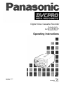
Digital Video Cassette Recorder
P
AJ-
Operating Instructions
Printed in Japan
VQT7626
S0698W
IMPORTANT
“Unauthorized
recording of
copyrighted
television programs, video tapes and other
materials may infringe the right of copyright
owners and be contrary to copyright laws.”
WARNING:
TO REDUCE THE RISK OF FIRE OR SHOCK
EXPOSE
THIS
HAZARD, DO
NOT
EQUIPMENT TO RAIN OR MOISTURE.
CAUTION: TO REDUCE THE RISK OF ELECTRIC SHOCK,
DO NOT REMOVE COVER (OR BACK).
NO USER SERVICEABLE PARTS INSIDE.
REFER TO SERVICING TO QUALIFIED SERVICE PERSONNEL.
CAUTION:
TO REDUCE THE RISK OF FIRE OR SHOCK
HAZARD AND ANNOYING INTERFERENCE,
USE THE RECOMMENDED ACCESSORIES
ONLY.
The lightning flash with arrowhead symbol,
within an equilateral triangle, is intended to
alert the user to the presence of uninsulated
“dangerous voltage” within the product’s
enclosure that may be of sufficient magnitude
to constitute a risk of electric shock to
persons.
FCC Note:
This device complies with Part 15 of the FCC Rules.
To assure continued compliance follow the attached
installation instructions and do not make any
unauthorized modifications.
The exclamation point within an equilateral
triangle is intended to alert the user to the
presence of important operating and
maintenance (service) instructions in the
literature accompanying the appliance.
This equipment has been tested and found to comply
with the limits for a class A digital device, pursuant to
Part 15 of the FCC Rules. These limits are designed
to provide reasonable protection against harmful
interference when the equipment is operated in a
commercial environment. This equipment generates,
uses, and can radiate radio frequency energy and, if
not installed and used in accordance with the
instruction manual, may cause harmful interference to
radio communications. Operation of this equipment in
a residential area is likely to cause harmful
interference in which case the user will be required to
correct the interference at his own expense.
CAUTION:
Do not install or place this unit in a bookcase,
built in cabinet or in another confined space
in order to keep well ventilated condition.
Ensure that curtains and any other materials
do not obstruct the ventilation condition to
prevent risk of electric shock or fire hazard
due to overheating.
Use this unit horizontally and do not place anything on
the top panel.
Cassette tape can be used only for one-side, one
direction recording. Two-way or two-track recordings
cannot be made.
Cassette tape can be used for either Color or Black &
White recording.
Do not attempt to disassemble the recorder.
There are no user serviceable parts inside.
If any liquid spills inside the recorder, have the
recorder examined for possible damage.
Refer any needed servicing to authorized service
personnel.
Do not insert fingers or any objects into the video
cassette holder.
Avoid operating or leaving the unit near strong
magnetic fields. Be especially careful of large audio
speakers.
Avoid operating or storing the unit in an excessively
hot, cold, or damp environment as this may result in
damage both to the recorder and to the tape.
Do not spray any cleaner or wax directly on the unit.
If the unit is not going to be used for a length of time,
protect it from dirt and dust.
Do not leave a cassette in the recorder when not in
use.
Do not block the ventilation slots of the unit.
2
Table of Contents
Introduction
5
Features
5
6
Controls and Their Functions
Front panel
6
Connector section
9
Tapes
11
Operation
12
Switching on the power and inserting the cassette
12
Stop mode
13
Recording
14
Pause/still recording (back-space assemble recording)
15
Playback
15
Cue and Review
16
Still-picture playback
16
Frame advance
16
Sound selection
16
Repeat playback
17
Time Code and User’s Bit
19
Time code
19
User’s bit
19
Setting the time code
20
Setting the user’s bit
20
Time code and user’s bit playback
21
Superimposed Display Screens
22
Set-up (Default Settings)
23
Set-up Menus
24
BASIC menu
24
OPERATION menu
25
INTERFACE menu
26
MEMORY MODE menu
27
TAPE PROTECT menu
27
TIME CODE menu
28
VIDEO menu
29
AUDIO menu
30
3
Table of Contents
30
RS-232C Interface
31
1. Hardware specifications
1) Interface specifications
31
2) Communication parameters
31
32
2. Software specifications
1) External interface specifications
32
2) Sending format (from personal computer to VTR)
32
3) Receiving format (from VTR to personal computer)
32
4) Command list
34
Error Messages
36
Video Head Cleaning
37
Condensation
37
Maintenance
37
Specifications
38
4
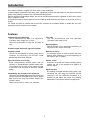
Introduction
The model AJ-D230H is a digital VTR which uses 1/4-inch wide tapes.
It features digital compression technology which significantly reduces the deterioration in the picture and sound
quality during dubbing compared with conventional analog systems.
With its compact and lightweight design, the unit can be carried around with the greatest of ease, and it is also
easy to install it in a rack.
An interactive format is used to perform the unit’s settings while monitoring the menus on the screen of the TV
monitor.
The model AJ-D230H is provided with an RS-232C connector as a standard feature to enable the unit to be
operated by remote control from a computer.
Features
Time code
This unit incorporates a time code generator
(TCG)/time code reader (TCR).
Compact size and light weight
The unit measures 8-7/16” wide, 5-1/4” high and 157/16”deep, and it weighs only 15.4 Ibs.
Grips are incorporated to make the unit easy to
carry.
2-channel digital audio with high sound quality
Repeat playback
Repeat playback can be performed continuously or
only once for any section of the tape.
Computer control
The unit can be operated by remote control from a
computer by connecting the RS-232C cable
between the unit and the computer.
Menu-driven set-up
An interactive system is used to perform the unit’s
settings while monitoring the menus appearing on
the screen of the TV monitor.
Up to 126 minutes of recording
Either news-gathering cassette tapes (max. 66
minutes) or general-purpose cassette tapes (max.
126 minutes) can be used. In both cases, the tape
is one-fourth of an inch wide to achieve a compact
design.
Remote control
Connection of the AG-A11 remote controller (option)
enables the unit to be operated at a distance of
about 5 meters.
Digital interface
By installing the digital interface board (option) and
connecting the unit using the DVCPRO terminal
(complying with the IEEE1394 standard), it is
possible to dub tapes with hardly any resulting
deterioration in the picture and sound quality at all.
Compatibility with consumer-use equipment
Consumer-use cassette tapes which have been shot
using a consumer-use digital camera can be played
back on this unit using the cassette adaptor (AJCS750P: option).
Please note that the LP mode is not supported.
5
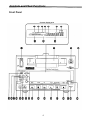
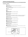
Controls and Their Functions
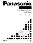
Front Panel
Counter display area
6
Controls and Their Functions
Front panel
POWER switch
When the ON side is pressed, the power is turned
on, and the counter display area lights.
Red: This lights when either the video or audio
signals
are
corrected or
playback
interpolated.
Cassette slot
A news gathering cassette, general-purpose
cassette or consumer-use cassette with an adaptor
is loaded through this slot. Consumer-use
cassettes can be played back only.
Level meter
This displays the audio signal levels.
The input audio signal levels are displayed during
recording and E-E selection; the output audio signal
levels are displayed during playback.
EJECT button
When this is pressed, the tape is unloaded, and
several seconds later the cassette is automatically
ejected.
When the counter display area shows the CTL
display, the display is now reset.
“Cassette loaded” display lamp
This lights when a cassette has been loaded into
the unit.
REC/REC INH lamp
This lights during recording.
REC:
REC INH: This lights when the cassette has been
set to the accidental erasure prevention
status.
It also lights when REC INHIBIT has
been set to ON on the setup menu.
In this status, recording is not possible.
REMOTE lamp
This lights when the LOCAL/MENU/REMOTE
switch has been set to the REMOTE position.
WIDE lamp
This lights in the 16:9 wide screen mode.
Counter display area
The TC and CTL counts, on-screen information and
messages appear in this area.
LOCAL/MENU/REMOTE switch
This is operated when menu settings are to be
performed or when the unit is to be controlled from
a remote location.
LOCAL:
For controlling the unit using the controls
on the unit’s operation panel.
MENU:
For setting the on-screen menu.
REMOTE: For controlling the unit with an RS-232C
or other external control unit.
INPUT SELECT switch
This is used to select the input signals.
LINE:
“Consumer-use cassette loaded” display lamp
This lights when a cassette recorded on a
consumer-use DV unit has been loaded.
REPEAT lamp
This lights during repeat playback.
SERVO lamp
This lights when the drum servo and capstan servo
are locked.
Channel condition lamps
blue
red) in
One of these lamps lights (green
accordance with the status of the error rates.
Green: This lights when the error rates for the video
and audio playback signals are both
satisfactory.
Blue: This lights when the error rate for either the
video or audio playback signals has
deteriorated. The playback picture is still
normal even while this lamp is lighted.
7
For recording signals which have been
supplied to the video signal input
connector.
S-VIDEO: For recording signals which have been
supplied to the S-VIDEO input connector.
OPTION: For supplying video and audio signals
from an optional board and recording
them.
BEGIN button
This sets the repeat playback start point, and it
displays the currently entered start point.
END button
This sets the repeat playback end point, and it
displays the currently entered end point.
CH3/CH4 lamp
This lights during DV format playback when the
audio signals have been set in CH3 and CH4.
AUDIO OUT SELECT button
This selects the audio signals which are to be
output.
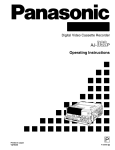
Controls and Their Functions
Headphone jack
When stereo headphones are connected here, the
recording or playback sound
“ can be monitored
through the headphones.
Volume control
This is for adjusting the headphones volume.
Remote control connector
When the remote controller (AG-A11) is connected
to this connector, the unit can be operated from a
distance by this controller instead of by its function
buttons. In this case, the LOCAL/MENU/REMOTE
switch must be set to the REMOTE position.
Volume recording level control
This is for adjusting the PCM audio signal CH1/CH2
recording level.
REW button
When this is pressed, the tape is rewound, and
when "TAPE" is set for the "S/F/R EE SEL" set-up
menu item, the playback picture can be monitored.
STOP button
When this is pressed, the tape stops traveling, and
when "TAPE" is set for the "S/F/R EE SEL" set-up
menu item, the still picture can be monitored. Even
in the stop mode, the drum continues to rotate with
the tape kept in close contact with the drum. After
the unit has been kept in the stop mode for a
specific period of time, it is automatically set to the
standby off mode in order to protect the tape. It is
set to the stop mode immediately after a cassette
has been loaded into the unit.
FF button
When this is pressed, the tape is fast forwarded,
and when "TAPE" is set for the "S/F/R EE SEL" setup menu item, the playback picture can be
monitored.
PLAY button
When this is pressed, playback commences. When
it is pressed together with the REC button,
recording commences.
PAUSE/STILL button
When this is pressed during recording, the tape
travel is temporarily stopped (pause mode). When
it is pressed again, recording is resumed.
When this is pressed during playback, the still
picture mode is established. When it is pressed
again, playback is resumed.
REC button
When this is pressed together with the PLAY
button, recording commences.
8
(AG-A11)
COUNTER button
This switches the display on the counter display
area.
CTL: The tape timer (control signal) is displayed.
TC: The time code is displayed.
UB: The user's bit is displayed.
Remaining tape:
The amount of tape remaining is displayed.
RESET button
When this is pressed in the CTL mode, the counter
display is reset to 00:00:00:00.
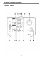
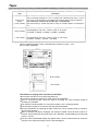
Controls and Their Functions
Connector section
9
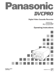
Controls and Their Functions
Connector section
AC IN connector
Use the power cord supplied to connect this connector to the power outlet.
SIGNAL GND terminal
This is connected to the signal ground terminal on the unit connected in order to reduce the
noise. It is not a safety ground.
Fan motor
This is for cooling the unit.
Handle
S-VIDEO IN connector
This is the input connector for the S-VIDEO video signals.
VIDEO IN connector
This is the input connector for the analog video signals.
SYNC IN connector
This is connected to the composite sync signals of a reference sync signal generator if
synchronization with an external reference sync signal is to be obtained during playback.
AUDIO IN connector
This is the input connector for the analog audio signals.
S-VIDEO OUT connector
This is the output connector for the S-VIDEO video signals.
VIDEO OUT connector
This is the output connector for the analog video signals.
MONITOR OUT connector
This is the output connector for the video monitor signals.
Superimposed video signals can be output from it.
AUDIO OUT connector
This is the output connector for the analog audio signals.
RS-232C connector
Connecting the optional RS-232C cable to this connector enables many kinds of
computerized operations to be performed for the unit.
RS-232C connector
10
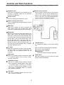
Tapes
Type
Description
Consumer-use
cassette
(S size cassette)
This is exclusively designed for use in consumer-use camera/recorder units. It can be
used in the unit for playback only provided that the cassette adaptor (option) is obtained.
Use of Panasonic consumer DV cassette tape is recommended.
Note that inserting a cassette tape without using the cassette adaptor can damage the
unit.
M size cassette
Recording/playback tape with a maximum length of 66 minutes
(AJ-P12MP, AJ-P24MP, AJ-P33MP, AJ-P46MP, AJ-P66MP)
L size cassette
Recording/playback tape with a maximum length of 126 minutes
(AJ-P34LP, AJ-P66LP, AJ-P94LP, AJ-P126LP)
Align the cassette tape with the center of the loading slot, and push it in gently. It will
then be loaded automatically.
M size cassette
L size cassette
<Precautions for playing back consumer-use DV tapes>
A consumer-use tape can be used for playback only.
A consumer-use tape recorded in LP mode cannot be played back.
Since a consumer-use tape cannot be used for recording, the unit’s functions related to
recording are prohibited.
The maximum traveling speed of a consumer-use tape is 32× normal tape speed.
The still-picture images on a consumer-use tape may be disturbed.
From the perspective of protecting the tape, refrain from cue-up operation using a consumertape wherever possible.
When a consumer-use tape is employed, the maximum duration of the still timer is set to 10
seconds, and the total time during which the unit is allowed to be left standing in the still mode
is set to 1 minute.
The time code read disabled display may appear when a search is performed on a consumeruse tape or the still-picture image of such a tape is displayed.
11
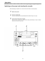
Operation
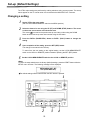
Switching on the power and inserting the cassette
Before attempting to operate the unit, make sure that it has been connected properly.
1
2
3
Switch on the power.
Insert the cassette tape.
Insert the cassette tape into its prescribed position without forcing it in any way.
Check that the STOP lamp has lighted.
When the tape is inserted, the cylinder starts rotating automatically, the tape is loaded,
and the unit is set to the stop mode.
2
1
3
12
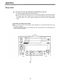
Operation
Stop mode
1
The unit is set to the stop mode when the STOP button is pressed.
The STOP lamp lights and the tape stops traveling.
In order to protect the tape, the unit is set to the tape protection mode after the period
of time set in the “STILL TIMER” set-up menu item has elapsed. (See page 27) When
the STOP, REW, FF or PLAY button is pressed, the unit is set to the corresponding
mode.
<Precautions for setting the still timer>
When the same part of the same tape is used repeatedly, the cumulative standby time in the
same place increases.
In order to protect the tape, set the standby time for the same place on the same tape to as
short a duration as possible.
1
13
Operation
Recording
1
Set the accidental erasure prevention tab on the cassette tape to “recording,” and
insert the tape.
2
Press the STOP button to set the unit to the stop mode.
3
Check that the REC INH lamp is off.
4
Selecting the video and audio input signals and adjusting the audio signal level
4-1
Selecting the video and audio input signals
1 Connect the signals which are to be recorded.
2 Select the input signals using the INPUT SELECT switch on the front panel.
4-2
Adjusting the audio signal level
1 Adjust the audio input signal level.
The audio signals are recorded at the appropriate level when the level
controls are set to the center click-stop position.
5
6
Press the PLAY button while holding down the REC button.
The REC and PLAY lamps light, and recording is commenced.
To stop recording, press the STOP button.
Recording is now ended, and the unit is set to the stop mode.
<Notes>
A recording cannot be made properly on a tape on which the recording protection signal has
been recorded as an input signal.
During recording, check that the SERVO lamp is lighted. If the lamp is flashing or off, the
images played back will be disturbed.
14
Operation
Pause/still recording (back-space assemble recording)
1
2
3
Press the PAUSE/STILL button while the cassette tape is playing.
If the “AUTO BACK” set-up menu item has been set to ON, the tape will be rewound for 1
or 2 seconds starting at the position where the PAUSE/STILL button was pressed.
(See page 25)
Press the REC button to set the unit to the REC PAUSE mode.
The monitor display now switches to the E-E screen.
Press the PAUSE/STILL button to start the recording.
The tape runs to the position where the PAUSE/STILL button was pressed in step 1, and
the recording is started.
<Note>
The E-E screen now appears.
Playback
1
2
3
Insert the cassette tape.
Press the PLAY button.
Normal playback is now commenced.
To stop playback, press the STOP button.
The VTR is now set to the stop mode.
<Note>
During playback, check that the SERVO lamp is lighted. If the lamp is off or flashing, the images
played back will appear disturbed.
Cue and Review
Keep pressing the FF or REW button during playback.
While the button is held down, the tape is cued or reviewed at approximately 10× normal tape
speed.
Normal playback is restored when the button is released.
The cue track sound is output during cue or review if the “SEARCH CUE” set-up menu item
has been set to ON. (See page 30)
Still-picture playback
Press the PAUSE/STILL button during playback.
When it is pressed again, normal playback is restored.
No sound is heard during still-picture playback.
15
Operation
Frame advance
The tape is advanced or reversed frame by frame when the FF or REW button is pressed
during playback.
No sound is heard during frame advance or reverse.
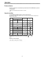
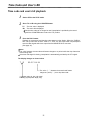
Sound selection
Use the AUDIO OUT SELECT button to select the desired sound.
By pressing the AUDIO OUT SELECT button, the mode for the audio output is selected in the
sequence shown below.
AUDIO OUT connectors
Mode
A
CH1 output
CH2 output
CH1
CH2
B
CH1
C
CH2
D
CH3
Display tube
CH1
CH2
CH3
CH4
CH1
CH3
CH4
CH2
CH4
LED
CH3
CH4
No display
CH3
CH4
E
CH3
No display
CH3
CH4
F
CH4
No display
CH3
CH4
CH1
CH2
CH3
CH4
G
CH1+CH3
CH2+CH4
The shading denotes that the selection is valid only
during playback using the DV format in the 4-channel
mode.
Sequence of mode selection
16
Off
On
Operation
Repeat playback
Setting the BEGIN and END points
[Menu mode]
1
2
Set the VTR to the menu mode.
(Set the LOCAL/MENU/REMOTE switch to the MENU position.)
Select the “BEGIN/END PRESET” set-up menu item, and press the MODE (REW)
button. (See page 27)
3
Select TC or CTL using the COUNTER button.
4
Select either BGN or END using either the BEGIN button or the END button.
5
6
7
8
Select the digit (flashing display) in which the change is to be made using the UP
(FF) and DOWN (STOP) buttons.
The frame digit cannot be selected. “00” is displayed for the frame value at all times.
Press the DATA+ (PAUSE/STILL) button or DATA– (PLAY) button to change the
value.
Upon completion of the settings, press the SET (REC) button.
The settings are now stored in the memory, and the display returns to the regular menu
screen.
Set the LOCAL/MENU/REMOTE switch to the LOCAL or REMOTE position.
<Notes>
is displayed.
When an item has no setting,
When repeat playback is initiated in this status, the start of the tape serves as the BEGIN
point and the end of the tape serves as the END point.
When the RESET button is pressed, the setting is reset to “00:00:00:00.”
If the MODE (REW) button is pressed without pressing the SET button upon completion of the
settings, the time code setting is canceled, and the display returns to the regular menu
screen.
When the BEGIN or END button is used to set the digit in which the change is to be made to
BGN or END, and then the DATA+ or DATA– button is pressed, it is possible to select whether
an item is to be set or left unset.
<Menu screen>
CTL
BGN
END
–00 : 00 : 00 : 00
+ 00 : 00 : 00 : 00
17
Operation
Setting the BEGIN and END points
[Front panel]
1
2
Set the VTR to the local mode.
(Set the LOCAL/MENU/REMOTE switch to the LOCAL position.)
Press the BEGIN or END button on the front panel to set the current position as the
BEGIN or END point.
Displaying the BEGIN and END points
1
2
Set the VTR to the remote mode.
(Set the LOCAL/MENU/REMOTE switch to the REMOTE position.)
When the BEGIN or END button on the front panel is pressed, the BEGIN or END
point is displayed while the button is held down.
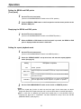
Setting the repeat playback mode
1
2
Set the VTR to the menu mode.
(Set the LOCAL/MENU/REMOTE switch to the MENU position.)
Select the “MEMORY MODE” set-up menu item, and select the repeat playback
mode. (See page 27)
Setting
OFF
3
Description of operation
Normal operation
MEM STOP
When the tape is fast forwarded or rewound, it stops near the BEGIN
point.
REPEAT 1
When the tape is played to the END point, it is rewound to the BEGIN
point where it stops.
CONTINUE
When the tape is played to the END point, it is rewound to the BEGIN
point and played back, and this sequence of operation is repeated.
Set the LOCAL/MENU/REMOTE switch to the LOCAL or REMOTE position.
<Note>
When the repeat play function is used over and over again for the same tape, the tape’s
images will deteriorate. Replace the tape with a new one after about a hundred repeat plays.
Bear in mind that no operation will result when repeat play is to be performed using a
consumer-use tape even if “CONTINUE” has been selected for set-up menu item No.300
(MEMORY MODE). (See page 27)
18
Time Code and User’s Bit
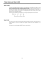
Time code
The time code signal generated by the time code generator is recorded on the tape as a time
code, it is read out by the time code (signal) reader, and used to display the absolute position of
the tape in increments of hours, minutes, seconds and frames.
The time code is written in the sub-code area (data area) of the helical track. For this reason, it
can be read out across a wide range of VTR playback speeds from the stop mode to slow
playback and to high-speed playback.
The time code is indicated by the display or by the figures superimposed onto the screen.
TCR 00 : 07 : 04 : 24
Hours Minutes Seconds Frames
User’s bit
The user’s bit is a 32-bit (8-digit) information frame contained in the time code signals which is
made available to the user. It enables the operator number and other information to be
recorded.
The figures 0 to 9 and the letters ABCDEF can be used for this bit.
19
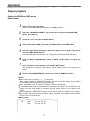
Time Code and User’s Bit
Setting the time code
1
2
3
4
5
6
7
Set the VTR to the menu mode.
(Set the LOCAL/MENU/REMOTE switch to the MENU position.)
Select the “TC PRESET” set-up menu item, and press the MODE (REW) button.
(See page 28)
Select the digit (flashing display) in which the change is to be made using the UP
(FF) and DOWN (STOP) buttons.
Press the DATA+ (PAUSE/STILL) button or DATA- (PLAY) button to change the
value.
Upon completion of the settings, press the SET (REC) button.
(The display returns to the regular menu screen.)
Press the SET (REC) button again.
(The settings are now stored in the memory, and the menu mode closes.)
Set the LOCAL/MENU/REMOTE switch to the LOCAL or REMOTE position.
<Notes>
The current time code value is displayed as the default setting.
When the RESET button is pressed, the setting is reset to “00:00:00:00.”
The time code cannot be set unless the “TC MODE” set-up menu item has been set to “PREC” or “P-FREE.” (See page 28)
If the MODE (REW) button is pressed without pressing the SET button upon completion of the
setting, the time code setting is canceled, and the display returns to the regular menu screen.
Setting the user’s bit
1
2
Set the VTR to the menu mode.
(Set the LOCAL/MENU/REMOTE switch to the MENU position.)
Select the “UB PRESET” set-up menu item, and press the MODE (REW) button.
(See page 28)
The remaining steps in the setting procedure are the same as for the time code.
20
Time Code and User’s Bit
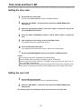
Time code and user’s bit playback
1
Set the VTR to the STOP mode.
2
Set to TC or UB using the COUNTER button.
TC : The time code is displayed.
UB : The user’s bit is displayed.
When the time code can no longer be read, interpolation is provided by the control
signal if the COUNTER button is set to the CTL position.
3
Press the PLAY button.
Playback is commenced, and the time code appears on the display. When the “DISPLAY
SEL” set-up menu item is set to “TIME” or “T, STA,” the time code value is superimposed
onto the video signals which are output from the MONITOR OUT connector.
(See page 24)
<Notes>
The colon between the seconds and frames changes to a period while the drop frame time
code is being read.
If the time code signal is missing, interpolation is automatically provided by the CTL signal.
The display changes as shown below.
T
R
00:07:04:24
The colon (” : ”) between the seconds and frames
changes to a period (" . “) in the drop frame mode.
appears when the time code signal
is missing (superimposed display only).
21
Superimposed Display Screens
When the MONITOR OUT connector has been connected to the TV monitor, the abbreviations
corresponding to the control signal, time code, etc. are displayed on the TV monitor.
Abbreviation
(control signal)
CTL
(time code playback value)
TCR
(user’s bit playback value)
UBR
REMAIN (remaining tape length)
TV monitor
Characters displayed
The background of the characters superimposed onto the display can be changed using the
“CHARA TYPE” set-up menu item. (See page 24)
TV monitor
TV monitor
Display position
The position where the characters are superimposed onto the display can be changed using the
“CHARA H-POS” and “CHARA V-POS” set-up menu items. (See page 24)
TV monitor
TV monitor
<Note>
The counter display is made to appear
for as long as the MODE button is held
down, enabling the settings to be
Even while the MODE
checked.
button is held down, the DATA+ and
DATA– buttons can be used to
perform settings while the actual
situation is checked.
Operating mode
When “T, STA” has been selected for the “DISPLAY SEL” set-up menu item, the VTR’s
operating mode is also displayed. (See page 24)
VTR operation mode
TV monitor
22
Set-up (Default Settings)
The VTR’s major settings are performed by making selections using a menu system. The set-up
menus appear on the TV monitor when it is connected to the MONITOR OUT connector.
Changing a setting
1
2
3
4
Set the VTR to the menu mode.
(Set the LOCAL/MENU/REMOTE switch to the MENU position.)
Select the item to be set using the UP (FF) and DOWN (STOP) buttons. The cursor
on the menu screen moves and selects the item.
The cursor ( ) is moved to the previous set-up menu item number using the DOWN
button and the next set-up menu item number using the UP button.
Press the DATA+ (PAUSE/STILL) button or DATA– (PLAY) button to change the
setting.
Upon completion of the setting, press the SET (REC) button.
The change is now stored in the memory.
To return from the new setting to the original setting, set the LOCAL/MENU/REMOTE
switch to the LOCAL or REMOTE position instead of pressing the SET (REC) button.
5
Set the LOCAL/MENU/REMOTE switch to the LOCAL or REMOTE position.
<Note>
To return the setup selections to the factory (default) settings, press the RESET button while the
SETUP. menu is shown. The following message is then displayed.
SETUP-MENU INIT. SET
OK? (PUSH REC KEY)
The default settings will be restored when the REC button is pressed.
1
2
23
3
4
Set-up Menus
BASIC menu
Setting
Item
No.
Superimposed
display
No.
000
DISPLAY SEL 0000
0001
0002
001
CHARA H-POS
0000
0001
0003
0007
002
CHARA V-POS
0000
0001
Description of settings
Superimposed
display
OFF This sets what is to be displayed for the superimpose
TIME signals output from the MONITOR OUT connector.
T, STA 0: No display
1: Only the time is displayed.
2: The time and operation mode are displayed.
0
1
:
3
:
7
This sets the horizontal position of the superimposed
characters (8 settings to choose from).
0 This sets the vertical position of the superimposed
1 characters (8 settings to choose from).
:
0007
3
:
7
0000
0001
WHITE
W/OUT
0003
003
CHARA TYPE
005
MENU INHIBIT 0000
0001
This selects the type of characters for the
superimposed display and menu display.
0: White characters appear on a black back ground.
1: White characters with black borders appear.
OFF This selects whether or not the menu settings are to be
ON fixed.
0: The settings are not fixed.
1: The settings are fixed (and cannot be changed).
The underlined number and item are the factory settings.
.
.
<Notes>
While setting “CHARA H-POS”, “CHARA V-POS”, and “CHARA TYPE”, the counter display can be
viewed by holding down the MODE button, allowing you to check the settings. You can also use the
DATA+ and DATA– buttons while holding down the MODE button to adjust the values while you are
viewing them.
To set ON or OFF for the “MENU INHIBIT” item, first press the DATA+ or DATA– button while holding
down the MODE button, and then select the setting.
Continuously after performing the settings, press the SET button (REC button) to exit the menu. The
MENU INHIBIT setting takes effect starting with the next menu mode.
24
Set-up Menus
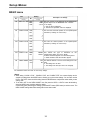
OPERATION menu
Setting
Item
No.
Superimposed
display
No.
LOCAL
ENABLE
0000
0001
DISABLE
ST EJ
1 0 1 TAPE TIMER
0000
0001
12H
24H
100
1 0 2 S/F/R EE SEL 0000
0001
Description of settings
Superimposed
display
This selects the switches on the front panel which can
be operated in the remote control mode.
0: None of the switches can be operated.
1: Only the STOP and EJECT switches can be operated.
This selects the CTL counter display.
0: ±12-hour display
1: 24-hour display
EE This selects the EE/VV output during stop, fast
TAPE forwarding or rewinding.
0: EE is output.
1: VV is output.
1 0 3 WIDE MODE
0000
0001
0002
AUTO
WIDE
NORMAL
104
TAPE IN MODE
0000
0001
0002
0003
TAPE END
0000
0001
0002
0003
STOP This selects the operation which follows when the
REW cassette is inserted.
PAUSE 0: STOP
PLAY 1: Rewind
2: Play pause
3: Play
STOP This selects the operation which follows when the tape
REW has reached the end.
R E W E J 0: Stop
EJECT 1: Rewind
2: This rewinds the tape and ejects it upon completion
of rewinding.
3: Eject
AUTO This selects the sync signals of the servo.
EXT 0: Synchronization with the input signals; if no input
signals are present, synchronization with the internal
signals.
1: During playback, synchronization with the SYNC IN
if these signals are not present,
signals;
synchronization with the internal signals.
105
MODE
106
SERVO REF
0000
0001
This selects the WIDE mode.
0: Automatic detection.
1: The screen mode is forcibly treated as WIDE.
2: The screen mode is forcibly treated as NORMAL.
(AUTO) VIDEO IN connector:
Synchronized playback is performed using standard video signals.
With non-standard video signals, the switching is performed in such a way that playback is
synchronized with the internal signals.
(EXT) SYNC IN connector:
Use standard signals as the SYNC signals.
Non-standard signals cannot be used. Use of the BB (black burst) signal is recommended.
When an out-of-sync state occurs due to SYNC signal switching or interruption
Set to the STOP EE mode or eject the cassette and then re-load it.
This makes it possible for the synchronization to be reset.
OFF This selects whether to automatically reverse (auto
0000
107
AUTO BACK
ON back) the tape to achieve back-space assemble
0001
recording.
0: No auto back
1: Auto back
The underlined number and item are the factory settings.
25
Set-up Menus
OPERATION menu
Item
No.
Setting
Superimposed
display
No.
Description of settings
Superimposed
display
DVCPRO This selects the format when an L cassette is used.
DV 0: DVCPRO mode
DVCAM 1: DV mode
2: DVCAM mode
108 FORMAT SEL 0000
0001
0002
<Note>
The cassette tape is played back in one of the modes listed below depending on the tape type and
settings used.
FORMAT SEL setting
Type
DVCPRO
DV
DVCAM
S size cassette
DV
DV
DVCAM
M size cassette
DVCPRO
DVCPRO
DVCPRO
L size cassette
DVCPRO
DV
DVCAM
Use tapes specially designed for DVCPRO applications with this unit. However, if DV tapes or DVCAM
tapes are to be used in the playback mode, it is recommended that playback be limited to as short a
period of time as possible.
0000
OFF This selects whether to inhibit recording on the VTR.
109 REC INHIBIT
0001
ON 0: Recording is not inhibited.
1: Recording is inhibited.
The underlined number and item are the factory settings.
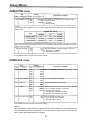
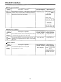
INTERFACE menu
Item
Setting
Description of settings
No.
Superimposed
display
200
BAUD RATE
201
DATA LENGTH 0000
0001
8BIT This sets the RS-232C data length.
7BIT
202
STOP BIT
0000
0001
1BIT This sets the RS-232C stop bit length.
2BIT
203
PARITY
0000
0001
0002
No.
0000
0001
0002
0003
0004
204 ACK RETURN 0000
0001
Superimposed
display
1200 This sets the RS-232C transfer rate (baud rate).
2400
4800
9600
19200
NONE This sets whether the RS-232C parity bit is to be used
ODD and, if so, whether with even or odd parity.
EVEN 0: The parity bit is not used.
1: The parity bit is used with odd parity.
2: The parity bit is used with even parity.
OFF This sets the RS-232C return data.
ON 0: The ACK code is not returned.
1: The ACK code is returned.
The underlined number and item are the factory settings.
<Note>
After the settings of items No.200 through No.203 have been changed, the new settings will not
take effect until the power is switched on. This means that the power must be turned off and
back on again after these settings are changed.
26
Set-up Menus
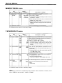
MEMORY MODE menu
Setting
Item
No.
Superimposed
display
300 MEMORY
MODE
No.
0000
0001
0002
0003
Description of settings
Superimposed
display
OFF This sets the memory operation.
MEM STOP 0: No memory operation.
REPEAT 1 1: The tape stops near the BEGIN point when it is fast
CONTINUE
forwarded or rewound.
2: When the tape reaches the end, it is rewound to the
BEGIN point where it stops.
3: When the tape reaches the end, it is rewound to the
BEGIN point where it is played, and this process is
repeated.
This sets the BEGIN point and END point.
301 BGN/END PRESET
The underlined number and item are the factory settings.
TAPE PROTECT menu
Setting
Item
No.
Superimposed
display
No.
Description of settings
Superimposed
display
400
STILL TIMER
0000
0001
0002
0003
0004
0005
0.5S
5S
10S
30S
1MIN
2MIN
401
SRC PROTECT
0000
0001
STEP This sets the tape protection operation which is
HALF performed when the unit has been left standing in the
pause mode.
This selects the time taken until the unit is set to the
tape protection mode when it has been left standing in
the stop, play pause or still mode.
(Units: S = seconds, MIN = minutes)
The setting for the time taken until the unit is set to
the tape protection mode when it has been left
standing in the REC PAUSE mode is fixed at 2
minutes.
0: Step (step FWD in the still or pause mode; step REV
in the REC pause mode)
1: Half loading (standby OFF)
402
DRUM STDBY 0 0 0
0001
403
STOP
PROTECT
0000
0001
OFF
ON
STEP
HALF
This sets whether or not the drum is to be stopped in
the STANDBY OFF mode.
0: The drum rotates at all times.
1: The drum is stopped in the STANDBY OFF mode.
This sets the tape protection operation to be performed
when the unit is left standing in the STOP mode.
0: Step
1: Half loading
The underlined number and item are the factory settings.
<Note>
When using a consumer DV cassette tape, tape protection mode is set after 10 seconds, even if
STILL TIMER is set to "30S", "1MIN" or "2MIN".
27
Set-up Menus
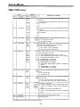
TIME CODE menu
Item
Setting
No.
Superimposed
display
No.
500
VITC POS-1
0000
0001
:
0006
:
0010
501
VITC POS-2
0000
0001
:
0008
:
0010
Description of settings
Superimposed
display
10L
11L
:
16L
:
20L
This sets the position where the VITC signal is to be
inserted.
(The same line as that selected for VITC POS-2 cannot
be selected.)
10L This sets the position where the VITC signal is to be
11L inserted.
: (The same line as that selected for VITC POS-1 cannot
18L be selected.)
:
20L
502
VITC BLANK
0000
0001
BLANK
THRU
503
TCG REGEN
0000
0001
0002
TC UB This selects the signal to be regenerated when the
TC TCG is in the REGEN mode. (item No. 507)
UB 0: Both the time code and user
1: Only the time code is regenerated.
This sets whether the VITC signal is to be output.
0: VITC signal is not output.
1: VITC signal is output.
2: Only the user's bit is regenerated.
504
BINARY GP
0000
0001
0002
0003
0004
0005
0006
0007
000
001
010
011
100
101
110
111
This sets the status for using the user's bit of the time
code generated by the TCG.
0: NOT SPECIFIED (character set is not used)
1: ISO CHARACTER (8bit character set complying
with ISO646 and ISO2022 is used)
2: UNASSIGNED-1 (not defined)
3: UNASSIGNED-2 (not defined)
4: UNASSIGNED-3 (not defined)
5: PAGE/LINE (SMPTE262M page/line multiplexing
system)
6: UNASSIGNED-4 (not defined)
7: UNASSIGNED-5 (not defined)
505
TCG CF FLAG
0000
0001
OFF This selects whether the CF flag of the TCG is to be set
ON ON.
0: CF flag is set OFF.
1: CF flag is set ON.
506
DF MODE
0000
0001
DF This selects the drop frame or non-drop frame mode for
NDF CTL and TCG.
0: CTL and TCG are used in the drop frame mode.
1: CTL and TCG are used in the non-drop frame mode.
507 TC MODE
0000
0001
0002
0003
P-REC
P-FREE
I-REGEN
E-VITC
This sets the TCG mode.
0: Internal TC PRESET is used in the REC RUN mode.
1: Internal TC PRESET is used in the FREE RUN
mode.
2: Internal TC is used in the REGEN mode.
3: VITC of input video signals is used in the REGEN
mode.
508
TC PRESET
This sets the time code generator value.
509
UB PRESET
This sets the user
The underlined number and item are the factory settings.
28
Set-up Menus
VIDEO menu
Setting
Item
No.
Superimposed
display
No.
Description of settings
Superimposed
display
600
VIDEO MODE 0000
0001
B/W
COLOR
For setting video signal recording and playback.
0: For using monochrome signals.
1: For using color signals.
To use monochrome signals for recording and
playback, set this item to the B/W mode. To use
normal color signals, set it to the COLOR mode.
If color signals are recorded in the B/W mode, the
playback images will appear with abnormal colors.
601
V-MUTE SEL
0000
0001
N-MUTE
LOW-RF
This selects whether the video signals are to be muted
during playback under low RF conditions or when the
servo lock is disengaged.
0: Video signals are not muted.
1: Video signals are muted.
602 CC (F1) BLANK
0000
0001
BLANK
THRU
This selects ON or OFF for the closed capture signal in
the first field.
0: Signal is forcibly blanked.
1: Signal is not blanked.
603 CC (F2) BLANK
0000
0001
BLANK This selects ON or OFF for the closed capture signal in
THRU the second field.
0: Signal is forcibly blanked.
1: Signal is not blanked.
604 STD/NSTD SEL 0000
0001
605
FREEZE SEL
0000
0001
AUTO This selects the video signal processing.
NSTD 0: Mode is set automatically according to the input.
1: Mode is forcibly set to nonstandard mode.
FIELD
FRAME
This selects which type of freeze mode is to be
established for the still picture during PLAY PAUSE or
frame advance.
0: Field freeze
1: Frame freeze
The underlined number and item are the factory settings.
29
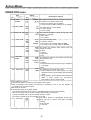
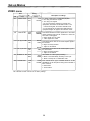
Set-up Menus
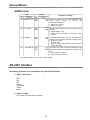
AUDIO menu
Item
No.
Superimposed
display
700
SEARCH CUE
Setting
No.
Description of settings
Superimposed
display
0000
0001
OFF This selects whether the cue audio signals are to be
ON output
during
search
or
during
fast
forwarding/rewinding (VV).
0: Signals are not output.
1: Signals are output.
701
DV PBATT
0000
0001
OFF
ON
This selects the audio output level during DV format
playback.
0: Normal playback level
1: Output level is controlled only during DV format
playback.
702
PB MUTE
0000
0001
OFF
ON
This selects whether the sound is to be muted during
playback at the back-space assemble recording points.
0: Sound is not muted.
1: Sound is muted.
However, it may not be possible to mute the sound at
the edit OUT point.
703
AUDIO REC IN 0000
0001
CUT This selects the audio processing information at the
FADE back-space assemble recording points recorded on the
tape.
0: Cut processing is selected
1: Fade processing is selected
The underlined number and item are the factory settings.
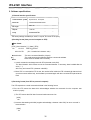
RS-232C Interface
The following functions can be controlled by using the RS-232C interface.
1. Basic operations
Eject
stop
play
rec/play
fast forward
rewind
pause
2. Status checks
The current VTR mode can be checked.
30
RS-232C Interface
1. Hardware specifications
1) Interface specifications
Connector: D-SUB, 25P, DCE specifications (straight cable supported)
Signal
Pin No.
Description
1
FG
Protective ground
2
SD (TXD)
Transmitted data
3
RD (RXD)
Received data
4
RS (RTS)
Request to send
5
CD (CTS)
Clear to send
6
DR (DSR)
Data set ready
7
SG
Signal ground
20
ER (DTR)
Data terminal ready
Example of wiring connections
VTR
Personal computer
Frame FG
1
FG
3
SD (TXD)
2
SD (TXD)
2
RD (RXD)
3
RD (RXD)
7
RS (RTS)
4
RS (RTS)
8
CD (CTS)
5
CD (CTS)
6
DR (DSR)
6
DR (DSR)
5
SG
7
SG
4
ER (DTR)
20
ER (DTR)
2) Communication parameters
The VTR’s communication parameters are shown below. To change any of these parameters, make the
changes using the menu.
Baud rate : 9600 bps
Bit length : 8 bits
Stop bit : 1 bit
: None
Parity
31
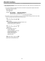
RS-232C Interface
2. Software specifications
1) External interface specifications
Communication system
Asynchronous, full duplex
Baud rate
1200/2400/4800/9600/19200
Bit length
8 bit/7 bit
Stop bit
1 bit/2 bit
Parity
NONE/ODD/EVEN
The factory settings are 9600 bps, 8 bits, 1 stop bit, and none for the parity.
2) Sending format (from personal computer to VTR)
Data format
[STX] [discrimination] [:] [data] [ETX]
3AH XX XX 03H
XX XX XX
02H
20H<XX<7FH
discrimination
data
(XX = hexadecimal character code)
: This is the command identifier (3 bytes).
: This code serves as the delimiter between a command and data.
: Data codes are added when necessary.
1. A send command must always start with STX (character code 02H).
The ‘discrimination’which follows next is the command identifier. If necessary, data is added after the
colon (" : ").
At the very end comes ETX (character code 03H).
2. When STX is re-sent before ETX is sent, the receive buffer inside the VTR is cleared (all data received
up to that moment will be lost), and the data is processed again with the re-received STX placed at the
head.
3) Receiving format (from VTR to personal computer)
The VTR responds to a send command with data in the following format.
1. First, the VTR returns the data which acknowledges whether the command from the computer was
received properly.
1) The VTR returns the ACK data if communication was error-free.
[ACK]
06H
2) It returns data starting with NAK (negative acknowledge; character code 15H) if an error occurred in
communication.
[NAK]
15H
32
RS-232C Interface
2. Next, after [ACK] is returned because communication was error-free, data is returned in the following format
by the operation of the VTR.
1) The response data (return data) format when the command from the personal computer was received
properly by the VTR is as follows.
[STX] [data] [ETX]
02H XX XX 03H
Example: Send command
[STX] QOP [ETX]
[STX] QCD [ETX]
Return data = Receive data
[ACK] [STX] OEJ [ETX]
[ACK] [STX] CD
[ETX]
2) If the data is incorrect or the trouble has occurred in the VTR, details indicating the reason why the data
could not be received are returned using the following format.
[STX]
E
R
0
0
02H 45H 52H 30H 30H XX
[ETX]
03H
Meaning of
1 (31H): Unknown command, or command execution error
2 (32H): Bad data code parameter error
3 (33H): Receiving buffer overflow error
[STX]
E
R
1
0
02H 45H 52H 31H 30H XX
[ETX]
03H
Meaning of
2 (32H): Front loading error
3 (33H): Loading error
4 (34H): Drum/capstan system error
5 (35H): Reel system error
6 (36H): Tension system error
7 (37H): Fan motor error
8 (38H): Dew error
[STX]
E
R
1
F
F
[ETX]
02H 45H 52H 31H 46H 46H 03H
System (servo communications) error
33
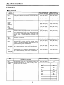
RS-232C Interface
4) Command list
Key commands
Send
command
Description of operation
Data transmitted by
personal computer
Data received in
response from VTR
OSP
(STOP)
All the VTR’s operations are stopped, and the VTR is set to
the stop mode.
[STX] OSP [ETX]
[STX] OSP [ETX]
OEJ
(EJECT)
Cassette is ejected.
[STX] OEJ [ETX]
[STX] OEJ [ETX]
OPL
(PLAY)
Playback is commenced.
[STX] OPL [ETX]
[STX] OPL [ETX]
ORW
(REWIND)
The tape is rewound.
[STX] ORW [ETX]
[STX] ORW [ETX]
[STX] OFF [ETX]
[STX] OFF [ETX]
[STX] OPA [ETX]
[STX] OPA [ETX]
[STX] ORC [ETX]
[STX] ORC [ETX]
The tape is fast forwarded.
OFF
(FAST
FORWARD)
OPA
(PAUSE)
This is the pause or pause release command.
When the VTR is in the playback mode, it is set to the stillpicture playback (STILL); when it is in the recording mode,
it is set to the pause (REC PAUSE) mode. The VTR’s
previous mode is restored when this command is sent
again.
ORC
(REC)
Recording is commenced.
ORP
(REC
PAUSE)
The recording pause (REC/PAUSE) mode is established
when the VTR is in the still-picture playback (STILL),
playback or recording mode. When this command is sent
again, the recording mode is established.
[STX] ORP [ETX]
[STX] ORP [ETX]
OAF
(ADVANCE
FIELD)
When the VTR is in the still-picture playback (STILL), the
tape is advanced frame by frame in the forward direction.
[STX] OAF [ETX]
[STX] OAF [ETX]
OAR
(ADVANCE
REVERSE
FIELD)
When the VTR is in the still-picture playback (STILL), the
tape is advanced frame by frame in the reverse direction.
[STX] OAR [ETX]
[STX] OAR [ETX]
Data transmitted by
personal computer
Data received in
response from VTR
Status command
Send
command
Description of operation
This command inquires as to the operation mode of the
QOP
(OPERATION VTR. The VTR returns one of the following codes in
MODE)
response to the QOP command.
34
[STX] QOP [ETX]
[STX]
[ETX]
VTR operation mode
Code
STOP
OSP
EJECT
OEJ
FF
OFF
REW
ORW
PLAY
OPL
STILL
OPP
RECORD
ORC
REC PAUSE
ORP
RS-232C Interface
Counter sense command
Data transmitted by
personal computer
Send
command
Description of operation
QCD
(COUNTER
SENSE)
This command inquires as to the current value of the
counter. The CTL counter value or TCR value is returned.
The counter keys on the front panel or the menu is used to
select the CTL counter and TCR values.
[STX] QCD [ETX]
Data received in
response from VTR
[STX] CDFS
[ETX]
Counter value
Counter value
For a CTL counter value
Sign Hours Minutes Seconds Frames
–: –sign (2DH)
+: Blank (20H)
For a TCR value
Hours Minutes Seconds Frames
Standby OFF commands
Send
command
Description of operation
Data transmitted by
personal computer
Data received in
response from VTR
OBF
(STANDBY
OFF)
This command sets the VTR to the standby OFF mode. It
is received when the VTR is in the stop mode.
[STX] OBF [ETX]
[STX] OBF [ETX]
OBN
(STANDBY
ON)
This command sets the VTR to the standby ON mode. This
operation is recognized when the VTR is in the standby
OFF mode.
[STX] OBN [ETX]
[STX] OBN [ETX]
Data transmitted by
personal computer
Data received in
response from VTR
Deck ID command
Send
command
QID
(DECK IN
SENSE)
Description of operation
This command inquires as to the TV system
accommodated by the VTR.
[STX] QID [ETX]
[STX]
[ETX]
AJ-D230 : NTSC system
AJ-D230E : PAL system
35
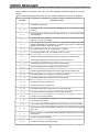
ERROR MESSAGES
When trouble has occurred in the VTR, one of the following messages appears on the tape
counter.
The VTR stops operating when any of the error numbers except E-00 and E-01 is displayed.
Description of error
Error No.
— d—
Condensation has formed.
E
00
This appears when the servo has been disengaged for 3 seconds during normal
playback.
E
01
This appears when dropouts have been detected for two or more seconds during
normal playback.
E
11
The reel base which operates in accordance with the size of the tape has been
locked for more than 2.5 seconds.
E
21
The cassette has not moved down even when 4 seconds have elapsed since it was
inserted. Alternatively, the cassette is not ejected even when 4 seconds have
elapsed since the EJECT button was pressed.
E
31
The loading operation was not completed within 4 seconds.
E
32
The unloading operation was not completed within 4 seconds.
E
41
The FG (rotational speed) signal has not been output from the cylinder motor.
E
42
The PG (phase) signal has not been output from the cylinder motor.
E
43
The rotational speed of the cylinder motor is abnormally high.
E
44
The rotational speed of the cylinder motor is abnormally low.
E
51
The FG (rotational speed) signal has not been output from the capstan motor.
E
52
The rotational speed of the capstan motor is abnormally high.
E
53
The rotational speed of the capstan motor is abnormally low.
E
61
The supply reel motor has locked up.
E
62
The take-up reel motor has locked up.
E
63
The rotational speed of the supply reel motor is abnormally high.
E
64
The rotational speed of the take-up reel motor is abnormally high.
E
65
A tension error has been detected.
E
66
The start or end processing operation has not been completed even though 7 or
more seconds have passed.
E
67
Communication error between SERVO and AVSYS. There is an error in the data.
E
68
Communication error between SERVO and AVSYS. The data has been fixed at
high or low.
E
69
An error occurred in communication between SERVO and AVSYS when the power
was turned on.
E
70
The fan motor stopped operating.
E
80
Trouble has occurred in the supply voltage.
36
Video Head Cleaning
This VTR comes with an auto head cleaning function which automatically reduces the amount of
dirt on the heads. However, to ensure the highest reliability, we recommend that you clean the
video heads every day.
Use the cleaning fluid designated by Panasonic.
Checking the hour meter
1
2
Set the VTR to the remote mode.
(Set the LOCAL/MENU/REMOTE switch to the REMOTE position.)
When the RESET button on the front panel is pressed, the cumulative numbers of
hours during which the drum and capstan have been used are indicated alternately
on the counter display for as long as the button is held down.
Cumulative drum rotation time
Cumulative capstan rotation time
Condensation
The principle according to which condensation forms is the same as that which causes droplets
of water (condensation) to form on the window panes of a heated room when it is cold outside.
Condensation forms on the VTR or its tape when it is moved to a location with a considerably
different temperature and humidity. More specifically, it forms when the VTR or tape is:
Brought into a very steamy and humid location or into a room where the heating was just
turned on.
Brought suddenly from an air-conditioned room to a very hot and humid location.
In such cases, do not turn the power on straight away but leave the unit standing for about 10
minutes. When condensation has formed in the unit, an error message lights up in the counter
display section, and the cassette tape is automatically ejected.
Keep the power on and wait until the error message is cleared.
Maintenance
Before performing any maintenance work, set the power switch to the OFF position and
disconnect the power cable from the AC outlet making sure that you take hold of the molded part
of the power plug.
Use a soft cloth to clean the cabinet. In order to get rid of stubborn dirt, dilute some neutral
kitchen detergent with water, dip a cloth into the solution, wring it out well, and wipe away the
dirt. Then wipe off any moisture which remains using a dry cloth.
Do not use paint thinners or benzine for cleaning purposes.
37
SPECIFICATIONS
GENERAL
Power supply:
Power consumption:
120 V AC, 50Hz-60Hz
49W
Ambient operating temperature:
Ambient operating humidity:
Weight:
Dimensions (W × H × D):
Recording format:
Recording tracks:
Time code:
Digital audio:
Cue track:
Control (CTL):
Tape speed:
Recording time:
41°F to 104°F (5°C to 40°C)
35% to 80%
15.4 Ibs. (7.0 kg)
8-7/16” × 5-1/4” × 15-7/16” (214 × 132 × 391 mm)
DVCPRO
Digital video
Recorded in sub-code area
2 channels
1 track
1 track
33.820 mm/sec.
126 minutes (using AJ-P126LP tape)
66 minutes (using AJ-P66MP tape)
1/4” thin magnetic layer metal tape
Within 3.5 min. (using AJ-P126LP tape)
Tape used:
FF/REW time:
VIDEO
(Digital video)
(Line IN/line OUT)
(Input connectors)
(Output connectors)
Sampling frequency:
Quantizing:
Error correction:
Video band:
Y/C delay:
K factor:
Line input:
SYNC input:
S-VIDEO:
13.5 MHz for Y; 3.375 MHz for PB/PR
8 bits
Reed-Solomon product code
30 Hz to 4.5 MHz (–1±1 dB) for Y
Less than 20ns
Less than 3%
BNC × 1; 1.0 VP-P, 75
BNC × 1; 1.0 VP-P, 75
4P × 1; Y: 1.0 VP-P, 75
C: 0.286 VP-P, 75 (burst level)
BNC × 1; 1.0 VP-P, 75
BNC × 1; 1.0 VP-P, 75
4P × 1; Y: 1.0 VP-P, 75
C: 0.286 VP-P, 75 (burst level)
Line output:
Monitor output:
S-VIDEO:
AUDIO
(Digital audio)
(Input connectors)
(Output connectors)
Sampling frequency:
Quantizing:
Frequency response:
Dynamic range:
Distortion:
Crosstalk:
Line input (CH1/CH2):
Line output (CH1/CH2):
Headphones output:
48 kHz
16 bits
20 Hz to 20 kHz ( :;I,” ii)
More than 85 dB (1 kHz, emphasis OFF, “A” weighted)
Less than 0.1% (1 kHz, emphasis OFF, reference level)
Less than –80 dB (1 kHz, between 2 channels)
PHONO × 2; –8 dBV, 47 k
PHONO × 2; –8 dBV, 1 k
M3 stereo, variable level (max. –32 dBV or more), 8
OTHER INPUT/OUTPUT CONNECTORS
Display Tube
RS-232C:
Wired remote control:
D-SUB, 25P, RS-232C interface
M2 jack (simple remote control)
Counter:
Audio level meter:
Other:
8 digits (CTL/TC/UB selectable, remaining tape)
18 steps
REC/REC INH, REMOTE, WIDE, “Consumer-use cassette
loaded” display, REPEAT, SERVO, Channel condition,
“Cassette loaded” display
38
Broadcast & Television Systems Company
Division of Matsushita Electric Corporation of America
Executive Office
One Panasonic Way (4B-7) Secaucus, NJ 07094
Service Centers
Eastern:
Southern:
Western:
One Panasonic Way, Panazip (2A-4), Secaucus, NJ 07094
(201)-348-7677 Fax (201)-348-7511
1225 Northbrook Parkway, Suite #170, Suwanee, GA 30174
(770)-338-6855 Fax (770)-338-6656
4001 West Alameda Ave., Suite 100, Burbank, CA 91505
(818)-562-1579 Fax (818)-562-6663
Parts Information & Ordering
9:00 am – 5:00 pm (EST) (800)-334-4881/24 hr.Fax (800)-334-4880
Technical Support
Emergency 24 hr Parts & Support (800)-222-0741
Training Information
Digital System Products (201)-392-6076
Service Literature
(201)-392-6281
Panasonic Canada Inc.
5770 Ambler Drive, Mississaugua, Ontario L4W 2T3 (905)-624-5010
Panasonic de Mexico S.A. de C.V.
Av angel Urraza Num. 1209 Col. de Valle 03100 Mexico, D.F. (52) 1 951 2127