1
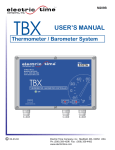
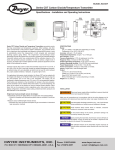
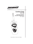
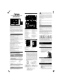
Size: A4
“
” is shown if the weather forecast is Rainy or
Cloudburst and outdoor temperature (any channel)
is under 0°C.
MAIN UNIT APPEARANCE:
A8 A9 A10 A11 A12
ADVANCED WEATHER STATION
MODEL IWA-80004
USER’S INSTRUCTIONS
A1
A2
A3
A4
A5
A6
A7
A13
A14
A15
A16
A17
A18
A19
p
If there is any inconsistency of weather forecast between
Local Weather Station and this unit, the Local Weather
Station's forecast should prevail. We will not hold responsible
for any trouble that may come up due to wrong forecasting
from this unit.
The trend pointer (LCD A10) indicates the trend of the
barometric pressure.
indicates the barometric pressure trend is increasing.
B6
B7
MODEL NO:IWA-80004
MADE IN CHINA
C2
B9
MAIN FEATURES:
Digital time with Manual Time Setting option
Daily Sunrise/Sunset and Moonrise/Moonset Time Display
for 244 cities in USA, Canada and Mexico.
Weather Forecast
- Weather Forecast with Sunny, Slightly Cloudy, Cloudy,
Rainy and Cloud Burst Animation
- Weather Girl with Suitable Clothing in Outdoor Condition
Barometric Pressure Measurement.
- Current and Past 12hr Absolute and Relative Barometric
Pressure Reading
- Barometric Pressure Bar Chart.
- Display in mb/hPa or in Hg Selectable.
433MHz RF Transmitting Frequency.
Maximum Three Selectable RF channels with Wireless Thermo
Sensor. (One Wireless Thermo Sensor Included)
Transmission Range: 100 feet (Open Area).
Measurable Range:
Indoor Temperature : 32°F ~ 122°F
Indoor Humidity : 20% ~ 99%
Outdoor Temperature : -4°F ~ +122°F
Max/Min Memory for Humidity, Indoor and Outdoor
Temperature.
Low-battery Indicator for Outdoor Thermo Sensor.
Perpetual Calendar Up to Year 2099.
12/24Hour Time Display Selectable.
2 Alarm Function
Moon Phase Display
Wall Mount or Table Stand Selectable.
BATTERY
C3
BEFORE USING THE TRANSMITTER
Part A-LCD
A1: Outdoor Temperature Trend
A2: Comfort Icon
A3: Indoor Temperature/Humidity
A4: Radio Control Icon
A5: Time Zone
A6: Radio Controlled Time
A7: Date, Month & Week
A8: Outdoor Temperature Moonrise Time
A9: Selected Channel
A10: Barometric Pressure Trend
B1: “SUN/MOON” Button
B2: “+ / (12/24)” Button
B3: “MODE” Button
B4: “- / ” Button
B5: “ALARM ON/OFF” Button
B6: “CHANNEL” Button
C1: Wall Mount Hole
433 MHz
1 unit
RF transmission range:
maximum 100 feet
Power
Main Unit
D4
D5
D7
D6
Dimension
Main Unit : 5.94 x 9.13 x 1.22 inch
Thermo Sensor Unit : 3.7 x 2.36 x 1.10 inch
BAROMETERIC PRESSURE TREAD
BAR GRAPH
1.
D1: Transmission Indication LED
D2: Outdoor Temperature
D3: Wall Mount Hole
D4: Channel Select Switch
Back View
D5: Battery Compartment
D6: °C/°F” button
D7: “TX” button
D8: Stand
Set Up:
- Insert batteries
- Use a pin to press the RESET (B12) button
WEATHER FORECAST FUNCTION
3.
After Batteries inserted or holding “WEATHER”
button (B7) for 3 seconds, Weather Icon (A11)
blinks. Enter the current weather condition by
pressing “▲“ (B8) or “▼“ (B9) buttons. Press
“WEATHER” button (B7) to confirm the setting.
The weather forecast may not be accurate if the
current weather condition entered is not correct.
The current weather status should be entered
again if the altitude of the weather station is changed.
(Barometric pressure is lower at higher altitude
location. Therefore, altitude change will affect
the weather forecast) The weather station will
start the first forecast at 6 hours after the current
weather status is entered.
Totally 5 different weather conditions in the weather
forecast.
Sunny
Slightly Cloudy
Cloudy
1.
2.
Weather Girl (A13) shows different clothing under
different weather condition and Outdoor temperature
(according to the lowest channel). This is to remind
you to wear suitable clothes or take an umbrella with
you before go to outdoor area.
If there is no Thermo Sensor
is registered in the main
unit, LCD shows :
THERMOMETER
1.
2.
Press “°C /°F” button (B8) to select Temperature
to be displayed in Celsius mode or Fahrenheit mode.
If the temperature is out of the measurable range,
LL.L (beyond the minimum temperature) or
HH.H (beyond the maximum temperature) will be
shown on the LCD.
MAXIMUM / MINIMUM TEMPERATURE /
HUMIDITY RECORDING FUNCTION
Rainy
2.
Cloudburst
The Barometric Pressure Reading at –2hr, -4hr,
-8hr and –12hr is recorded and shown on Barometric
Pressure Bar Graph (A12). The Graph is displayed
in both hPa and inHg.
WEATHER GIRL
1.
: DC 1.5 V 2A size x 3 pcs
Thermo Sensor Unit : DC 1.5 V 3A size x 2 pcs
- Press “HISTORY” button (B7) to view the past 12 hour
Barometric Pressure history. The hour is indicated on the LCD.
0 HR = Current Barometric Pressure Reading
-1HR = Barometric Pressure Reading in 1 hour ago
-2HR = Barometric Pressure Reading in 2 hour ago……..etc
Hold “▲” button (B8) for three seconds to select the unit
for Barometric Pressure Meter in inHg or mb / hPa.
D8
Front view
REMOTE SENSOR
No. of remote unit:
D3
D2
2.
RF transmission frequency:
C3: Stand
D1
0 °C to 45 °C
32 °F to 113 °F
-20 °C to 55 °C
-4 °F to 131 °F
C2: Battery Compartment
THERMO SENSOR UNIT APPEARANCE
SPECIFICATIONS
Recommended operating range:
- Press “Absolute/Relative” button (B10) for three seconds
to select Absolute or Relative pressure display. “Abs” is
shown for Absolute pressure; “Rel” is shown for Relative
pressure.
- Absolute pressure is the actual pressure measured by
the Main Unit.
- Relative pressure can be adjusted to sea level’s pressure
by holding “Absolute/Relative” button (B10) for 3 seconds.
- Press “ ▲“ (B8) or “▼“ (B9) key to adjust, press
“Absolute/Relative” button (B8) to confirm. Check the Local
Weather Station for Sea Level pressure.
- Press “HISTORY” button (B7) to view the past 12 hours
Barometric Pressure history. The hour is indicated on LCD (A14).
Press “HISTORY” button (B7)
B7: “HISTORY/ WEATHER” Button
B8: “▲(UP) / °C/ °F”Button
B9: “▼(DOWN)”Button
B10: “Relative /Absolute” Button
B11: “MAX/MIN” Button
B12: “RESET” Button
Part C- STRUCTURE
Main Unit
: DC 1.5 V 2A size x 3 pcs
Thermo Sensor Unit : DC 1.5 V 3A size x 2 pcs
MAIN UNIT
A11: Weather Forecast
A12: Barometric Pressure Bar Graph
A13: Weather Girl
A14: Past Hour(Pressure History)
A15: Absolute/ Relative Barometric
Pressure Reading
A16: Moon phase
A17: Moonrise/Moonset
A18: Time Selected Country
A19: Sunrise/Sunset Time
BAROMETERIC PRESSURE READING
Part B-BUTTON
1.
Recommended operating range:
indicates the barometric pressure trend is decreasing.
Wireless Weather Station
IWA-80004
B8
Thank you for your purchase of this advanced
weather station. The utmost care has gone into the design
and manufacture of your clock. Please read the
instructions carefully and keep the manual for future
reference.
The receiver unit has a clear, easy-to-read display that
shows the indoor/outdoor temperature, time, date, month
and day of the week. It will receive and display temperature
readings from the wireless remote sensor. The 433 MHz
technology means no wire installation is required and
you can place the sensor anywhere within the 100 feet
transmission zone.
indicates the barometric pressure trend is steady.
C1
B10
B11
B9
Press “MAX/MIN” button (B11) to show the maximum or
minimum of indoor/outdoor Temperature/Humidity.
“
” is shown on the LCD if maximum Temperature
/Humidity is shown.
“
” is shown on the LCD if minimum Temperature/
Humidity is shown.
Hold “MAX/MIN” button (B11) for 3 seconds to clear the
recorded maximum and minimum reading.
OUTDOOR THERMO SENSOR UNIT
REGISTRATION PROCEDURE
1.
2.
3.
4.
The main unit automatically starts receiving
transmission from Outdoor Thermo Sensor after
Weather condition setting. Outdoor temperature
digits (A8) blinks.
Insert the batteries in the Thermo Sensor Unit.
The sensor unit automatically transmits temperature
to the main unit. (Battery compartment (D5) of thermo
sensor is located behind the back cover, unscrews
to open.)
For having more than one external transmitter
(Maximum3), select the Channel, CH1, CH2 or
CH3 to ensure each sensor is transmitting at difference
channel before inserting batteries. The channel
select switch (D4) is at the back of the thermo
sensor unit.
Press “TX” button (D7) on the thermo sensor unit to
transmit temperature to the main unit manually. The
main unit gives a “beep” sound if it received the
temperature.
DISPLAY OUTDOOR TEMPERATURE
1.
Press “CHANNEL” button (B6) to view the 3
Channels’ temperature. The sequence is shown
as follow:
Press “CHANNEL”Button
Display the three
channels alternatively
2.
3.
Hold “CHANNEL” (B6) button for 3 seconds to
cancel unused channel. It will automatically register
a new channel again if a new channel is received.
If there is no temperature displayed in existing channel
(“- - . –“is displayed on the LCD), hold “CHANNEL”
button (B6) for 3 seconds to cancel that channel
and receive the channel again (“Beep” sound can
be heard.) Then, press “TX “button (D7) on the thermo
sensor unit to transmit signal to the main unit manually
The trend pointer displayed (A1) indicates the trend
of the outdoor temperature.
SUNRISE/SUNSET AND MOONRISE/
MOONSET TIME DISPLAY FUNCTION
1.
2.
3.
4.
5.
6.
7.
8.
After setting the Calendar, Local Country and
City in the Time Setting Mode, the Main Unit
calculates the Sunrise/Sunset and Moonrise/
Moonset. The Sunrise/Sunset and Moonrise/
Moonset time digit blinks during the calculation.
Press “SUN/MOON” button (B1) to display
the Sun Hours of the selected day.
Hold “SUN/MOON” button for (B1) 3 seconds to
enter Sunrise/Sunset and Moonrise/Moonset
Time Quick Checking Mode. Location digits (A18) blinks
Enter “Country”, “City”, “Year”, “Month” and “Day”
which you would like to check.
Press “+” (B2) and “-“(B4) button to adjust and
press “SUN/MOON” button (B1) to confirm setting.
The Sunrise/Sunset and Moonrise/Moonset time
digit blinks during the calculation. After Calculation,
Sunrise/Sunset and Moonrise/Moonset time is
shown. The location digits (A18) keep blinking
to indicate the Main Unit is still in Quick Checking
Mode. Press “SUN/MOON” button (B4), or after
15 seconds, to return to normal mode.
If moonrise or moonset occur at next day, then
“MOONRISE +1” or “MOONSET +1” will be
displayed.
If there is no moonrise or moonset occur on
someday, “
”will be displayed on the LCD
The Sunrise/Sunset and Moonrise/Moonset time
display is just for reference only. For exact Sunrise/
Sunset and Moonrise/Moonset time, please refer
to your Local Weather Station.
MOON PHASE DISPLAY
The Moon Phase (A16) of each day is shown on the LCD.
A
Indicates the outdoor temperature is steady.
C
D
E
F
G
Press “ °C /°F” button (D6), on the Thermo Sensor unit,
to select Temperature to be displayed in Celsius
mode or Fahrenheit mode.
MANUAL TIME SETTING
1.
2.
Hold “MODE” button (B3) for 3 seconds to enter
Clock/Calendar setting Mode.
Press “+” (B2) or “-” (B4) buttons to adjust the setting
and press “MODE” button (B3) to confirm each setting.
The setting sequence is shown as follow:
Hour, Minutes, Second, Year, Month, Day, Day-of-week,
Country and City.
12/24 HOUR DISPLAY MODE
1.
Press “12/24” button (B2) to select 12 or 24 hours
mode.
2 DAILY ALARM FUNCTION
1.
Press “ MODE” button (B3) to select to view:
Time
Alarm Time1 (“
” Shown)
Alarm Time 2 (“ ” Shown)
2.
3.
4.
When viewing Alarm Time 1 or Alarm Time 2,
hold “MODE” button (B3) for 3 seconds to enter that
Alarm Time setting. Press “+” (B2) or “-” (B4) buttons
to adjust the alarm time.
Press “MODE” button (B3) to confirm each setting.
When viewing Alarm Time 1 or Alarm Time 2,
press “ALARM ON/OFF” button (B5) to switch
that alarm ON or OFF.
Press “MODE”(B3), “+”(B2), “-“(B4) or
“SUN/MOON” (B4) button to stop the alarm.
FCC STATEMENT
This device complies with Part 15 of the FCC Rules.
Operation is subject to the following two conditions:
(1)
(2)
WARNING:
NOTE:
This equipment has been tested and found to comply
with the limits for a Class B digital device, pursuant to
Part 15 of the FCC Rules. These limits are designed to
provide reasonable protection against harmful
interference in a residential installation.
This equipment generates, uses and can radiate radio
frequency energy and, if not installed and used in
accordance with the instructions, may cause harmful
interference to radio communications. However, there
is no guarantee that interference will not occur in a
particular installation. If this equipment does cause
harmful interference to radio or television reception,
which can be determined by turning the equipment off
and on, the user is encouraged to try to correct the
interference by one or more of the following measures:
•
B: Waxing Crescent C: First Quarter
D: Waxing Gibbous
E: Full Moon
G: Last Quarter
H: Waning Crescent
F: Waning Gibbous
LOW BATTERIES INDICATOR
NOTE:
- Use a pin to press the reset button (B12) if the Unit
does not work properly.
- Avoid placing the clock near interference sources
/metal frames such as computer or TV sets.
- The clock loses its time information when the batteries
is removed.
- Buttons will not function while scanning for WWVB
time signal or thermo sensor’s signal unless they are
well received or stopped manually.
- All Setting Modes will automatically exit in 15 seconds
without any adjustment.
NOTE:
Attention! Please dispose of used unit or batteries in
an ecologically safe manner.
PLACING THE TRANSMITTER OUTSIDE
The transmitter should be located in an area protected
from direct sunlight and rain. Place the sensor under a
covered location like a roof overhand or under the eaves.
This will ensure accurate temperature readings. The
transmitter comes with a wall mounting/desktop holder.
When mounting on a wall, screw in place the holder
using the top and bottom holes. Then secure the transmitter
in the holder. The holder is also equipped with a table
stand. With the transmitter secured on the holder, retract
the leg on the rear of the holder and place on a flat surface.
This device may not cause harmful interference,
and
This device must accept any interference
received, including interference that may cause
undesired operation.
Changes or modifications to this unit not expressly
approved by the party responsible for compliance could
void the user’s authority to operate the equipment.
H
Low battery icon “
“appear at particular channel
indicating that Thermal Sensor Unit of the channel is
Indicates the outdoor temperature is decreasing in low battery status. The batteries should be replaced.
4.
If you're in the US and would like to contact our
Customer Care department directly, please visit:
www2.oregonscientific.com/service/support.asp
OR
For international inquiries, please visit:
www2.oregonscientific.com/about/international.asp.
•
•
A: New Moon
Indicates the outdoor temperature is
increasing.
B
ABOUT OREGON SCIENTIFIC
Visit our website (www.oregonscientific.com) to learn
more about Oregon Scientific products.
•
Reorient or relocate the receiving antenna.
Increase the separation between the equipment
and receiver.
Connect the equipment into an outlet on a circuit
different from that to which the receiver is
connected.
Consult the dealer or an experienced radio / TV
technician for help.
DECLARATION OF CONFORMITY
The following information is not to be used as contact
for support or sales. Please call our customer service
number
(listed
on
our
website
at
www.oregonscientific.com or on the warranty card for
this product) for all inquiries instead.
We
Name:
Address:
Oregon Scientific, Inc.
19861 SW 95th Place, Tualatin,
Oregon 97062 USA
DECLARE THAT THE PRODUCT
Product No.:
Product Name:
IWA-80004
ADVANCED WEATHER STATION
is in conformity with Part 15 of the FCC Rules.
Operation is subject to the following two conditions:
1)
2)
This device may not cause harmful interference.
This device must accept any interference
received, including interference that may cause
undesired operation.
ADVANCE WEATHER STATION
IWA -80004
C 2008 Oregon Scientific. All rights reserved