1
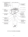
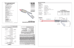
User’s Guide
®
http://www.omega.com
e-mail: [email protected]
LV-1101 & LV-1102
Non-Magnetic Liquid Level Switches
MADE
IN
USA
WARRANTY/DISCLAIMER
OMEGA ENGINEERING, INC. warrants this unit to be free of defects in materials and
workmanship for a period of 13 months from date of purchase. OMEGA Warranty adds an
additional one (1) month grace period to the normal one (1) year product warranty to cover
handling and shipping time. This ensures that OMEGA’s customers receive maximum
coverage on each product.
If the unit should malfunction, it must be returned to the factory for evaluation. OMEGA’s
Customer Service Department will issue an Authorized Return (AR) number immediately upon
phone or written request. Upon examination by OMEGA, if the unit is found to be defective it will
be repaired or replaced at no charge. OMEGA’s WARRANTY does not apply to defects resulting
from any action of the purchaser, including but not limited to mishandling, improper interfacing,
operation outside of design limits, improper repair, or unauthorized modification. This
WARRANTY is VOID if the unit shows evidence of having been tampered with or shows evidence
of being damaged as a result of excessive corrosion; or current, heat, moisture or vibration;
improper specification; misapplication; misuse or other operating conditions outside of
OMEGA’s control. Components which wear are not warranted, including but not limited to
contact points, fuses, and triacs.
OMEGA is pleased to offer suggestions on the use of its various products. However,
OMEGA neither assumes responsibility for any omissions or errors nor assumes liability
for any damages that result from the use of its products in accordance with information
provided by OMEGA, either verbal or written. OMEGA warrants only that the parts
manufactured by it will be as specified and free of defects. OMEGA MAKES NO OTHER
WARRANTIES OR REPRESENTATIONS OF ANY KIND WHATSOEVER, EXPRESSED OR
IMPLIED, EXCEPT THAT OF TITLE, AND ALL IMPLIED WARRANTIES INCLUDING ANY
WARRANTY OF MERCHANTABILITY AND FITNESS FOR A PARTICULAR PURPOSE ARE
HEREBY DISCLAIMED. LIMITATION OF LIABILITY: The remedies of purchaser set forth
herein are exclusive and the total liability of OMEGA with respect to this order, whether
based on contract, warranty, negligence, indemnification, strict liability or otherwise, shall
not exceed the purchase price of the component upon which liability is based. In no event
shall OMEGA be liable for consequential, incidental or special damages.
CONDITIONS: Equipment sold by OMEGA is not intended to be used, nor shall it be used: (1) as
a “Basic Component” under 10 CFR 21 (NRC), used in or with any nuclear installation or activity;
or (2) in medical applications or used on humans. Should any Product(s) be used in or with any
nuclear installation or activity, medical application, used on humans, or misused in any way,
OMEGA assumes no responsibility as set forth in our basic WARRANTY/DISCLAIMER language,
and additionally, purchaser will indemnify OMEGA and hold OMEGA harmless from any liability
or damage whatsoever arising out of the use of the Product(s) in such a manner.
RETURN REQUESTS / INQUIRIES
Direct all warranty and repair requests/inquiries to the OMEGA Customer Service Department.
BEFORE RETURNING ANY PRODUCT(S) TO OMEGA, PURCHASER MUST OBTAIN AN
AUTHORIZED RETURN (AR) NUMBER FROM OMEGA’S CUSTOMER SERVICE DEPARTMENT
(IN ORDER TO AVOID PROCESSING DELAYS). The assigned AR number should then be
marked on the outside of the return package and on any correspondence.
The purchaser is responsible for shipping charges, freight, insurance and proper packaging to
prevent breakage in transit.
FOR WARRANTY RETURNS, please have
the following information available BEFORE
contacting OMEGA:
1. P.O. number under which the product was
PURCHASED,
2. Model and serial number of the product
under warranty, and
3. Repair instructions and/or specific
problems relative to the product.
FOR NON-WARRANTY REPAIRS, consult
OMEGA for current repair charges. Have the
following information available BEFORE
contacting OMEGA:
1. P.O. number to cover the COST
of the repair,
2. Model and serial number of product, and
3. Repair instructions and/or specific problems
relative to the product.
OMEGA’s policy is to make running changes, not model changes, whenever an improvement is possible.
This affords our customers the latest in technology and engineering.
OMEGA is a registered trademark of OMEGA ENGINEERING, INC.
© Copyright 1996 OMEGA ENGINEERING, INC. All rights reserved. This document may not be copied, photocopied,
reproduced, translated, or reduced to any electronic medium or machine-readable form, in whole or in part, without
prior written consent of OMEGA ENGINEERING, INC.
omega.com
TM
OMEGA®
OMEGAnet On-Line Service
http://www.omega.com
SM
Internet e-mail
[email protected]
Servicing North America:
USA:
ISO 9001 Certified
Canada:
One Omega Drive, Box 4047
Stamford, CT 06907-0047
Tel: (203) 359-1660
e-mail: [email protected]
976 Bergar
Laval (Quebec) H7L 5A1
Tel: (514) 856-6928
e-mail: [email protected]
FAX: (203) 359-7700
FAX: (514) 856-6886
For immediate technical or application assistance:
USA and Canada: Sales Service: 1-800-826-6342 / 1-800-TC-OMEGASM
Customer Service: 1-800-622-2378 / 1-800-622-BESTSM
Engineering Service: 1-800-872-9436 / 1-800-USA-WHENSM
TELEX: 996404 EASYLINK: 62968934 CABLE: OMEGA
Mexico and
Latin America:
Tel: (95) 800-TC-OMEGASM
En Espan˜ol: (203) 359-1660 ext: 2203
FAX: (95) 203-359-7807
e-mail: [email protected]
Servicing Europe:
Benelux:
Postbus 8034, 1180 LA Amstelveen, The Netherlands
Tel: (31) 20 6418405
FAX: (31) 20 6434643
Toll Free in Benelux: 06 0993344
e-mail: [email protected]
Czech Republic:
Ostravska 767, 733 01 Karvina
Tel: 42 (69) 6311899
e-mail: [email protected]
France:
9, rue Denis Papin, 78190 Trappes
Tel: (33) 130-621-400
Toll Free in France: 0800-4-06342
e-mail: [email protected]
FAX: 42 (69) 6311114
FAX: (33) 130-699-120
Germany/Austria: Daimlerstrasse 26, D-75392 Deckenpfronn, Germany
Tel: 49 (07056) 3017
Toll Free in Germany: 0130 11 21 66
e-mail: [email protected]
FAX: 49 (07056) 8540
United Kingdom: 25 Swannington Road,
ISO 9002 Certified
P.O. Box 7, Omega Drive,
Broughton Astley, Leicestershire,
Irlam, Manchester,
LE9 6TU, England
M44 5EX, England
Tel: 44 (1455) 285520
Tel: 44 (161) 777-6611
FAX: 44 (1455) 283912
FAX: 44 (161) 777-6622
Toll Free in England: 0800-488-488
e-mail: [email protected]
It is the policy of OMEGA to comply with all worldwide safety and EMC/EMI regulations that
apply. OMEGA is constantly pursuing certification of its products to the European New Approach
Directives. OMEGA will add the CE mark to every appropriate device upon certification.
The information contained in this document is believed to be correct but OMEGA Engineering, Inc. accepts
no liability for any errors it contains, and reserves the right to alter specifications without notice.
WARNING: These products are not designed for use in, and should not be used for, patient connected applications.
Unpacking Instructions
Remove the Packing List and verify that you have received all equipment,
including the following (quantities in parentheses):
LV-1101 or LV-1102 level switch (1)
Operator’s Manual (1)
If you have any questions about the shipment, please call the OMEGA Customer
Service Department.
When you receive the shipment, inspect the container and equipment for signs of
damage. Note any evidence of rough handling in transit. Immediately report any
damage to the shipping agent.
NOTE
The carrier will not honor damage claims unless all shipping
material is saved for inspection. After examining and removing
contents, save packing material and carton in the event reshipment is necessary.
From the Technical Library of
i
General Description
The OMEGA® LV-1100 Series Liquid Level Switches feature a non-magnetic
design suitable for application where magnetic particles (ie: rust) are present.
The LV-1100 Series also feature rugged metal construction and a buoyancy
adjustment to allow the unit to be used with fluids down to SP.GR. = .06.
The LV-1101 features a single float design; the LV-1102 featurs a two float
design.
Features
• Rugged Industrial Design
• Non-Magnetic Design – Suitable For Rusty Environments
• 15A SPDT Switch Directly Controls Pump
• Continuously Adjustable Float Buoyancy Control to Allow Use in Fluids
With Specific Gravity Down to 0.6
• For Use With Water, Seawater, Sewage, Slurries, and Oils, Glycols, Soap
Solutions
• Model LV-1102 Also For Use With Chlorinated Organics, Medium
Concentrated Acids and Bases
NOTE
The LV-1101 has a Single Float Design; the LV-1102 has a Two
Float Design
1
Specifications
Working Fluid Specific
Gravity Range:
Adjustable between 0.6 and 1.0+
Nom. Working
Pressure/Temperature:
300 PSIG @ 180˚F max.
Liquid Level Change
To Activate Switch:
1/4 inch
Relay Switch:
SPDT 15A @ 125 or 250 Vac; 10,000,000
operations median
Option “D”:
Dual SPDT relays; nominal difference flow
between the two relay actuation points is 5%
Electrical Cable Fitting:
Water resistant strain relief for cable diameter
.250" ±.025"
Wetted Parts:
Model LV-1101: red brass body, phosphor
bronze float shaft, 316 SS screws and washers,
302 SS float, Buna N seal and cork-chloroprene
gasket;
Model LV-1102: 316 SS body, float shaft,
screws and washers, 302 SS float, Viton seal
and Teflon gasket
Size:
Fits through 2" NPT hole
Weight:
3 lbs.
Installation Dimensions
2
Installation
The LV-1101 Series Level Switches are supplied with a 2" x 1" TT bushing
threaded in place with 2 to 3 wraps of Teflon tape, which must be intact or
renewed if bushing and switch are separated before assembly in tank. Apply
a minimum of 2 to a maximum of 3 wraps of Teflon tape to the male threads
of the bushing. This is especially important if the unit is to be used in metal
fittings where coarse threads could bind if not lubricated.
Thread the unit into the tank and tighten until a good, no leak seal is obtained.
Make sure that the arrows molded on the body casting and printed on the
label are pointed vertically downward.
Remove the cover and test for proper switch action by applying multimeter
probes to the COM, NO and NC terminals of the microswitch while
actuating the switch lever arm.
The unit is supplied with the adjusting spring in the relaxed condition.
Leave the spring in the relaxed condition and fill the vessel until the float is
submerged. If the switch is actuated, proceed with the electrical wiring.
If the specific gravity of the working fluid is too low to lift the float and
actuate the switch, then the buoyancy adjustment feature must be used. To
adjust the buoyancy, turn the leadscrew CLOCKWISE until the switch is
actuated. Lower the liquid level until the float is clear of the liquid and the
switch is de-actuated. Raise the liquid level again until the float is submerged
and the switch actuates. If no further spring bias adjustment is required,
proceed with wiring.
Electrical Wiring
1. WIRING THE LV-1101/1102 WITH THE STRAIN RELIEF CABLE FITTING:
a. Remove the gland nut and tapered rubber grommet from the strain
relief cable fitting and slide them over the cable with the gland nut
going on first.
NOTE
Check the match of the outside diameter of the cable with the inside
diameter of the grommet. No more than .020" of play should be
evident.
b. Strip the outer jacket of the cable back 5 1/2 inches. Strip the insulation
from the individual conductors approximately 1/4".
c. Spade Lugs supplied with each switch. Remove them from the terminal
strip and crimp or solder to appropriate leads.
d. Feed cable up through cable fitting and attach leads to terminal strip per
Figure 1 or Figure 2 Wiring Schematics, below.
e. Push the rubber grommet into the conical hole in the cable fitting,
allowing enough cable to protrude from the opposite side to allow some
slack in the leads attached to the terminal strip. Grip the cable to
prevent rotation and thread the gland nut onto the cable fitting to seal
the grommet tightly to the cable.
3
WARNING
THESE DEVICES ARE NOT EXPLOSION-PROOF. IF THESE LEVEL SWITCHES ARE INTENDED FOR USE
WITH FLAMMABLE LIQUIDS, OR IN HAZARDOUS AREAS, THE MECHANICAL RELAY INSIDE CAN BE
MADE INTRINSICALLY SAFE WHEN PROPERLY WIRED TO AN INTRINSICALLY SAFE RELAY SWITCH,
SUCH AS OMEGA’S LVC 550 SERIES INTRINSICALLY SAFE RELAYS. THEY MUST BE INSTALLED IN
ACCORDANCE WITH THE NATIONAL ELECTRIC CODE (NEC) BY PERSONNEL EXPERIENCED WITH
INTRINSIC SAFETY WIRING.
2. WIRING THE LV-1101/1102 W/OPTION ‘D’ WITH STRAIN RELIEF
CABLE FITTING.
a. Remove the gland nut and tapered rubber grommet from the strain
relief cable fitting and slide them over the cable with the gland nut
going on first.
NOTE
Check the match of the outside diameter of the cable with the
inside diameter of the grommet. No more than .020" of play
should be evident.
b. Strip the outer jacket of the cable back 2 inches. Strip the insulation from
the individual conductors approximately 1/4".
c. Each microswitch is supplied with 3 flag slip-on terminals. Remove
from the microswitch and crimp or solder to the appropriate leads.
d. Feed the cable up through the cable fitting and attach the leads to the
microswitches per Figure 1 or Figure 2 Wiring Schematics, below.
e. Push the rubber grommet into the conical hole in the cable fitting. Slide
the cable thru until the end of the jacket is flush with the inboard end of
the cable fitting. Grip the cable to prevent rotation and thread the gland
nut onto the cable fitting to seal the grommet tightly to the cable.
3. If using a fitting other than the strain relief cable fitting, attach the fitting to
the body and attach the conduit to the fitting and wire to local code per
Figure 1 or Figure 2 Wiring Schematics.
Microswitch actuation point may be monitored by an audible click or with
an OHM meter before connecting line power to the terminal strip or by
monitoring the voltage supplied to the load through the microswitch.
4
Figure 1: Wiring Schematic for power applied to the load when the liquid
level is LOWER than the set point (power to the load is interrupted when the
liquid level is ABOVE the set point).
Figure 2: Wiring Schematic for power applied to the load when the liquid
level is HIGHER than the set point (power to the load is interrupted when the
liquid level is BELOW the set point).
5
6
Notes
7
Where Do I Find Everything I Need for
Process Measurement and Control?
OMEGA…Of Course!
TEMPERATURE
Thermocouple, RTD & Thermistor Probes, Connectors,
Wire: Thermocouple, RTD & Thermistor
Calibrators & Ice Point References
Recorders, Controllers & Process Monitors
Infrared Pyrometers
Panels & Assemblies
PRESSURE/STRAIN FORCE
Transducers & Strain Gauges
Load Cells & Pressure Gauges
Displacement Transducers
Instrumentation & Accessories
FLOW/LEVEL
Rotameters, Gas Mass Flowmeters
Air Velocity Indicators
Turbine/Paddlewheel Systems
Totalizers & Batch Controllers
& Flow Computers
pH/CONDUCTIVITY
pH Electrodes, Testers & Accessories
Benchtop/Laboratory Meters
Controllers, Calibrators, Simulators & Pumps
Industrial pH & Conductivity Equipment
DATA ACQUISITION
Data Acquisition & Engineering Software
Communications-Based Acquisition Systems
Plug-in Cards for Apple, IBM & Compatibles
Datalogging Systems
Recorders, Printers & Plotters
HEATERS
Heating Cable
Cartridge & Strip Heaters
Immersion & Band Heaters
Flexible Heaters
Laboratory Heaters
ENVIRONMENTAL MONITORING AND CONTROL
Metering & Control Instrumentation
Refractometers
Pumps & Tubing
Air, Soil & Water Monitors
Industrial Water & Wastewater Treatment
pH, Conductivity & Dissolved Oxygen Instruments
M0775/0297