1
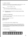
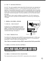
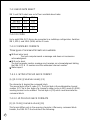
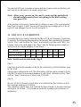
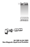
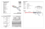
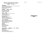
User’s Guide
http://www.omega.com
e-mail: [email protected]
DRA-DCC-8
DIGITAL TO 8 CURRENT LOOP CONVERTER
omega.com
TM
®
OMEGA
OMEGAnetSM On-Line Service
http://www.omega.com
USA:
ISO 9001 Certified
One Omega Drive, Box 4047
Stamford, CT 06907-0047
Tel: (203) 359-1660
FAX: (203) 359-7700
e-mail: [email protected]
USA and Canada:
Mexico and
Latin America:
Benelux
Czech Republic:
France:
Germany/Austria:
United Kingdom:
ISO 9002 Certified
Internet e-mail
[email protected]
Canada:
976 Bergar
Laval (Quebec) H7L 5A1
Tel: (514) 856-6928
FAX: (514) 856-6886
e-mail: [email protected]
Sales Service: 1-800-826-6342 / 1-800-TC-OMEGASM
Customer Service: 1-800-622-2378 / 1-800-622-BESTSM
Engineering Service: 1-800-872-9436 / 1-800-USA-WHENS M
TELEX: 996404 EASYLINK: 62968934 CABLE: OMEGA
Tel: (95) 800-TC-OMEGASM
En Espanol: (95) 203 359-7803
FAX: (95) 203-359-7807
e-mail: [email protected]
Postbus 8034, 1180 LA Amstelveen, The Netherlands
Tel: (31) 20 6418405
FAX: (31) 20 6434643
Toll Free in Benelux: 06 0993344
e-mail: [email protected]
Ostravska 767,733 01 Karvina
Tel:42(69)6311899
FAX:42(69) 6311114
e-mail: [email protected]
9, rue Denis Papin, 78190 Trappes
Tel: (33) 130-621-400
FAX: (33) 130-699-120
Toll Free in France: 0800-4-06342
e-mail: [email protected]
Daimlerstrasse 26, D-75392 Deckenpfronn, Germany
Tel: 49 (07056) 3017
FAX: 49 (07056) 8540
Toll Free in Germany: 0130 11 21 66
e-mail: [email protected]
25 Swannington Road,
P.O. Box 7, Omega Drive,
Broughton Astley, Leicestershire,
Irlam, Manchester,
LE9 6TU, England
M44 5EX, England
Tel: 44 (1455) 285520
Tel: 44 (161) 777-6611
FAX: 44 (1455) 283912
FAX: 44 (161) 777-6622
Toll Free in England: 0800-488-488
e-mail: [email protected]
It is the policy of OMEGA to comply with all worldwide safety and EMC/EMI regulations that apply.
OMEGA is constantly pursuing certification of its products to the European New Approach Directives.
OMEGA will add the CE mark to every appropriate device upon certification.
The information contained in this document is believed to be correct but OMEGA Engineering, Inc.
accepts no liability for any errors it contains, and reserves the right to alter specifications without notice.
WARNING: These products are not designed for use in, and should not be used for, patient connected
applications.
Contents
1. MOUNTING INSTRUCTIONS
2. REPLACING FUSES
3. ASSEMBLY
4. SUPPLY VOLTAGE
5. MODES OF OPERATION
5.1 0-20 or 4-20mA output current selection
5.2 Switch Settings
6. PARALLEL CONTROL MODE
6.1 PLC Interface
6.2 The "E" (ENABLE) Terminal
7. SERIAL CONTROL MODE
7.1 RS232c / RS422 Select
7.2 RS422 Termination
7.3 Serial Control Switch Settings
7.4 Serial Communication Parameters
7.4.1 Baud Rate Select
7.4.2 ID Code
7.4.3 Command Formats
8. SELF TEST MODES
8.1 Self Test # 1
8.2 Self Test # 2
8.3 Self Test # 3
9. MULTIDROP CONFIGURATION
10. PUTTING THE UNIT INTO OPERATION
11. CALIBRATION
12. SPECIFICATIONS
1
1. MOUNTING INSTRUCTIONS
The DRA-DCC-8 is designed for standard DIN rail mounting.
Place the unit on the upper part of the mounting rail with the fastening tab facing
down. Using a suitable flat screwdriver loosen the tab slightly and attach the unit
to the rail. Once the tab is loosened, ensure that the unit is fastened securely in
place.
2. REPLACING FUSES
In order to replace a blown fuse, the unit has to be disassembled, as follows:
a. Take off both terminal strips by removing the four screws at the edges.
Note: This does not require disconnecting the cables connected to the strips.
b. Remove the front panel using a suitable flat screwdriver. Press down gently on
the plastic springloaded tabs located in the slots either side of the unit.
c. Disconnect the flat connector which couples the LED circuit on the front panel.
d. Replace the blown fuse.
WARNING: Never install a fuse rated more than 800mA
3. ASSEMBLY
The DRA-DCC-8 unit includes
two printed circuit cards
designated as P.N 7041 and
P.N 7040. The two printed
circuit cards should occupy
the slots in the enclosure
according to fig 1.
Figure 1
Insert the two printed cards into their slots. Connect the flat cable between them.
Connect the front panel flat cable. The panel must be inserted into the grooves on
both sides of the case while pressing down until a distinct "click" is heard. Assembly
is completed by laying the terminal strips in place.
Note: The terminal strips are polarized and must not be placed backwards.
2
4. SUPPLY VOLTAGE
The DRA-DCC-8 is powered by a DC power supply at a range of 15-32Vdc. In order
to determine the minimum supply voltage, use the following equation:
Vmin = 8 + Rload(Ω) * 0.02
where:
Vmin is the minimum required supply voltage.
Rload(Ω) is the maximum output load including the leads resistance.
Note: If Vmin turns to be less than 15V, the minimum required voltage
should be 15 Vdc.
5. MODES OF OPERATION
The DRA-DCC-8 unit can be operated in several modes, determined by an internal
array of 8 DIP switches as follows:
4-20 or 0-20mA output current mode
Parallel control mode
Serial control mode
Self test mode
5.1 0-20 OR 4-20mA OUTPUT CURRENT MODE
Two current output spans are available: 4-20mA or 0-20mA selected by SW6.
The DRA-DCC-8 receives 12 bits of data which determine the output current value.
A channel data value of 4095 (FFF) is always interpreted as a 20mA output current.
A channel data value of 0 (000) will produce a 0mA output current when SW6
is OFF, or 4mA when ON.
5.2 SWITCH SETTINGS
Parallel Control Mode
MODE
0-20mA
4-20mA
S1
OFF
OFF
S2
OFF
OFF
S3
X
X
S4
X
X
S5
X
X
S6
OFF
ON
S7
OFF
OFF
3
Serial Control Mode
BAUD RATE (BPS)
300
4800
9600
19200
SW5 MSB
S1
OFF
ON
OFF
ON
MODE
SELF TEST#1
SELF TEST#2
SELF TEST#3
S2 S3
S4 S5
OFF
OFF
UNIT ID CODE
ON
ON
S6
S7
ON=4-20mA ON
ON
OFF=0-20mA ON
ON
Self Test Mode
S1
ON
OFF
S2
OFF
ON
ON
ON
S3
S4
X
X
S5
S6
X
*
S7
OFF
OFF
*
OFF
S6
*
S7
OFF
X
* according to para #5.2
6. PARALLEL CONTROL MODE
MODE
PARALLEL MODE
S1
OFF
S2
OFF
S3
S4
X
S5
* according to para #5.2
In the parallel control mode, the DRA-DCC-8 unit is controlled via a 15 bit bus.
Three Address bits (A0-A3) select the proper current output channel and 12 Data
bits (D0-D11) determine its value (A0 and D0 are MSB). The DRA-DCC-8
microprocessor continuously scans the input vector (Address + Data) terminals
and updates its memory tables upon recognizing a new vector. The unit is
asynchronous in nature. The data should be valid for at least 160 microseconds.
SINK
6.1 PLC INTERFACE
The PLC's output modules can be divided into
three popular types; TTL output module, 24Vdc
sink type and 24Vdc source type.
There is a jumper selector on printed circuit card
PN 7040 which selects between Sink/Source
input. (TTL output module should usualy be
considered as sink type). See figure 2.
4
Figure 2.
SOURCE
6.2 THE "E" (ENABLE) TERMINAL
For E="1" the unit is enabled, which means that all input vectors are received and
the output is updated. When E="0" the unit ignores any new input vector. The E
terminal is recommended to be used as a strobe for parallel data which has a long
setup time. In this case the following sequence is recommended: prior to applying
a new vector, the E terminal should be set to logical 0 (inhibit state), then the new
input vector should be imposed. Once the new data is set, the E terminal should
be pulsed.
The E terminal is also used for multidrop configuration. The 15 bit vectors are
applied to the units in parallel and the selection is carried out by controlling the
"E" inputs.
7. SERIAL CONTROL MODE
7.1 RS232c / RS422 SELECT
he DRA-DCC-8 is equipped with two serial
communication ports: The RS232c and the
RS422. A jumper switch at the right side of the
DIP switch array is used to select the required
communication type. See figure 3.
RS-422
Figure 3.
7.2 RS422 TERMINATION
RS-232c
The SW8's ON state terminates the RS422 receiver terminals with a 100W load.
In a multidrop configuration, the last (most distant) DRA-DCC-8 unit should be
terminated in order to match the transmission lines.
Note: Only one termination load per RS422 communication link is permissible.
7.3 SERIAL CONTROL SWITCH SETTINGS
S1
S2
BAUD RATE
S3
S4
ID CODE
S5
S6
*
S7
ON
* according to para #5.2
7.4 SERIAL COMMUNICATION PARAMETERS
The communication protocol is 8 bit ASCII, even parity, and one stop bit.
5
7.4.1 BAUD RATE SELECT
SW1 and SW2 select one out of four available baud rates.
SW1
SW2
300 BPS
4800 BPS
OFF
ON
OFF
OFF
9600 BPS
19200 BPS
OFF
ON
ON
ON
7.4.2 ID CODE
Up to eight DRA-DCC-8s can be connected in a multidrop configuration. Switches
SW3, SW4, and SW5 (MSB) set the ID code.
7.4.3 COMMAND FORMATS
Three types of command formats are available:
Without echo back
The host computer sends a massage and does not receives an
acknowledgment.
With echo back
The host computer sends a message and receives an acknowledgment stating
the DRA-DCC-8 ID number and the addressed channel number.
Status report
7.4.3.1. WITHOUT ECHO BACK FORMAT
[A] [ID CODE] [CHANNEL VALUE] [CR]
The character A begins the command block.
The second byte is the ID code (07). The third byte is the addressable channel
number (07). Up to four bytes of a channel's value can be in BCD mode (0-4095).
Leading zeroes can be omitted. The last byte is [CR] which must terminate the
command block.
7.4.3.2. WITH ECHO BACK FORMATS
[C] [ID CODE] [CHANNEL VALUE] [CR]
This format differs only in the opening character. After every command block
transfer, the DRA-DCC-8 echoes back the following:
6
[C] [ID CODE CHANNEL] [LF] [CR]
Note: If the value is omitted it will be treated as zero. Separators such as
blanks or commas are not allowed.
Example:
Channel 4 in DRA-DCC-8 no. 7 has to receive the value of 981. Echo back is required
The command format is:
[C] [7] [4] [981] [CR]
The echo back will be: C 7 4
Note: The channel numbers on the DRA-DCC-8 front panel are designated
from 1 to 8, in binary they are designated from 0 to 7.
Note: When applying the echo back mode, it is advisable to wait for the
echo back before transmitting a new command.
7.4.3.3 STATUS REPORT FORMAT
[S] [ID CODE] [CR]
The addressed DRA-DCC-8 unit will respond with the values stored in its eight
channels. The response will start with S, ID code, following with eight channel
values separated with commas and [LF] [CR] as terminators.
Example:
DRA-DCC-8 unit number 3 has the following stored data: ch1: 300, ch2: 1270,
ch3: 0, ch4: 4087, ch5: 2099, ch6: 764, ch7: 3078, ch8: 550. The response from
the device will be:
S3,300,1270,0,4087,2099,764,3078,550 [LF] [CR].
Note: Wait until the status report has terminated before transmitting new
commands.
8. SELF TEST MODES
The DRA-DCC-8 is provided with three test modes.
MODE
SELF TEST#1
SELF TEST#2
SELF TEST#3
S1
ON
OFF
S2
OFF
ON
ON
ON
S3
S4
X
X
X
S5
S6
X
*
S7
OFF
OFF
*
OFF
* according to para #5.2
7
8.1 SELF TEST #1 (Communication Ports Test)
In order to test the serial communication ports, this test mode converts the unit to
a transponder for ASCII characters. Any transmitted character will be echoed to
the host terminal. The host parameters should be set to:
Baud rate : 4800, Word length: 8 bits, Parity: even, Stop bit: 1
8.2 SELF TEST #2 (Same Leve)l
In this test mode, the DRA-DCC-8 unit ignores the address field. All the outputs
are set according to the data field only.
8.3 SELF TEST #3 (Saw Tooth)
In this test mode, only one output channel (according to the address setting) will
produce a saw tooth wave form in which the whole value range is used.
9. MULTIDROP CONFIGURATION
Up to eight DRA-DCC-8 units can be installed in a multidrop configuration using
the RS422 communication port.
The controller's RS-422 transmitter is connected to the units' receivers while the
controller's RS-422 receiver is connected to the units' transmitters.
As the communication cable might be several thousand feet long, it is necessary
to terminate the end of the line with its characteristic impedance in order to avoid
reflections in the transmission line causing data distortion. SW8 in its ON state
terminates the Rx inputs with a 100Ω load.
10. PUTTING THE UNIT INTO OPERATION
The DRA-DCC-8 is supplied with a set configuration for parallel control mode.
The DIP switch setting is:
MODE
PARALLEL 4-20mA
S1
OFF
S2
OFF
S3
OFF
S4
OFF
S5
OFF
S6
S7
ON OFF
The communication port selector (see para #7.1) is set to RS232C.
The unit should be set up according to the required configuration.
Before applying voltage to the unit see para #4 for power supply consideration.
8
The channel LEDs are connected in series with the output current so that they will
light only as an indication of a closed current loop.
Note: After every power on, the unit is reset and the initialized
default output currents are according to the SW6 setting
(see para #5.2).
In the parallel control mode, internal pull-up resistors on each of the input terminals
keep them in logical 1 state. The unit will recognize input voltage up to 0.5V as
logical 0 and voltages from 4V to 60V as logical 1.
11. DRA-DCC-8 CALIBRATION
Generally there is no need to calibrate the DRA-DCC-8 unit. However if calibration
is required, the following steps should be carried out: Two potentiometer trimmers,
one for "Zero" and the other for "Span" are located on printed card 7040. The
trimmer close to the card edge is the "Zero". Use the following switch setup for
switching all the outputs between 4 and 20mA
MODE
ALL CH. = 4mA
ALL CH. = 20mA
S1
OFF
OFF
S2
OFF
ON
S3
X
X
S4
X
X
S5
X
X
S6
S7
ON OFF
ON OFF
Note: Set the unit to sink mode (fig.2).
Step 1:
Select one channel (for example ch.#1) for the initial tuning. Set the DIPswitch array
to "all 4mA".
Apply supply voltage to the unit. The initial state of all the output currents is 4 mA.
Use SW2 to switch all the outputs between 4 and 20mA. Iteratively set the "Zero"
and the "Span" trimmers for 4.00mA and 20.00mA.
Step 2:
Monitor all the 8 channels in 4mA state, and calibrate the Zero trimmer so that
their average readings is 4.000mA.
Then repeat for 20mA state, and calibrate the Span trimmer so that their average
readings is 20.000mA. This procedure should be repeated until calibration is
satisfactory.
9
12. SPECIFICATIONS
10
INPUTS:
PARALLEL INPUTS
Parallel & Serial control inputs
3 - Output current loop address
12 - Output current value (Data)
1- Enable (E)
LOGIC LEVELS:
0<"0"<0.5V, 4 <"1"< 60V
DATA HOLD TIME:
160 microsecond
MAXIMUM PARALLEL INPUT RATE:
6000 updates per second
SERIAL COMMUNICATION
RS232c full duplex
RS422 full duplex
BAUD RATES:
300, 4800, 9600, 19200 BPS
PARITY:
Even
STOP BIT:
One
STATUS REPORT:
Reports as interrogated
MULTIDROP CAPABILITY:
Up to eight units
OUTPUTS:
OUTPUT CURRENT SPAN:
OUTPUT CURRENT SETTLING TIME:
8 continues current loops
0-20mA or 4-20mA (user selected)
4.2 ms max. for 99% of step
POWER SUPPLY:
15-32 Vdc (regulated)
CURRENT CONSUMPTION:
85mA max.
MAXIMUM LOOP RESISTANCE:
According to Rmax(KΩ)= (Vsupply -6)/20
ACCURACY:
±0.1% of span typical, ±0.2% of span max.
RESOLUTION:
0.025% of span typical,0.05% of span max.
INDICATORS:
Yellow Power On LED
8 Red output channel LEDs
AMBIENT TEMPERATURE
Operation:
Storage:
-10 to 60 Co (14 to 140 F)o
-25 to +85 C (-13 to 185 F)
RELATIVE HUMIDITY:
5 to 95%, non condensing
HOUSING
Box:
Terminals:
Plastic Polycarbonate
According to IP 50 DIN 40050
According to IP 20 DIN 40050
MOUNTING:
Standard DIN rail
FUSE:
630mA fast blow (5x20mm)
WEIGHT:
0.7Kg (1.5 lb.)
DIMENSIONS:
73.2H x 200W x 121mmD (2.88"x7.88"x4.76")
o
o
WARRANTY/DISCLAIMER
OMEGA ENGINEERING, INC. warrants this unit to be free of defects in materials and workmanship
for a period of 13 months from date of purchase. OMEGA Warranty adds an additional one (1) month
grace period to the normal one (1) year product warranty to cover handling and shipping time. This
ensures that OMEGA’s customers receive maximum coverage on each product. If the unit should malfunction,
it must be returned to the factory for evaluation. OMEGA’s Customer Service Department will issue an Authorized
Return (AR) number immediately upon phone or written request. Upon examination by OMEGA, if the unit is
found to be defective it will be repaired or replaced at no charge. OMEGA’s WARRANTY does not apply to defects
resulting from any action of the purchaser, including but not limited to mishandling, improper interfacing,
operation outside of design limits, improper repair, or unauthorized modification. This WARRANTY is VOID if
the unit shows evidence of having been tampered with or shows evidence of being damaged as a result
of excessive corrosion; or current, heat, moisture or vibration; improper specification; misapplication; misuse
or other operating conditions outside of OMEGA’s control. Components which wear are not warranted, including
but not limited to contact points, fuses, and triacs.
OMEGA is pleased to offer suggestions on the use of its various products. However,
OMEGA neither assumes responsibility for any omissions or errors nor assumes
liability for any damages that result from the use of its products in accordance
with information provided by OMEGA, either verbal or written. OMEGA warrants
only that the parts manufactured by it will be as specified and free of defects.
OMEGA MAKES NO OTHER WARRANTIES OR REPRESENTATIONS OF ANY KIND
WHATSOEVER, EXPRESSED OR IMPLIED, EXCEPT THAT OF TITLE, AND ALL
IMPLIED WARRANTIES INCLUDING ANY WARRANTY OF MERCHANTABILITY AND
FITNESS FOR A PARTICULAR PURPOSE ARE HEREBY DISCLAIMED. LIMITATION
OF LIABILITY: The remedies of purchaser set forth herein are exclusive and the
total liability of OMEGA with respect to this order, whether based on contract,
warranty, negligence, indemnification, strict liability or otherwise, shall not exceed
the purchase price of the component upon which liability is based. In no event
shall OMEGA be liable for consequential, incidental or special damages.
CONDITIONS: Equipment sold by OMEGA is not intended to be used, nor shall it be used: (1) as a “Basic
Component” under 10 CFR 21 (NRC), used in or with any nuclear installation or activity; or (2) in medical
applications or used on humans. Should any Product(s) be used in or with any nuclear installation or activity,
medical application, used on humans, or misused in any way, OMEGA assumes no responsibility as set forth
in our basic WARRANTY / DISCLAIMER language, and additionally, purchaser will indemnify OMEGA and
hold OMEGA harmless from any liability or d a m a g e w h a t s o e v e r a r i s i n g o u t o f t h e u s e o f t h e
P r o d u c t ( s ) i n s u c h a m a n n e r.
RETURN REQUESTS / INQUIRIES
Direct all warranty and repair requests/inquiries to the OMEGA Customer Service Department.
BEFORE RETURNING ANY PRODUCT(S) TO OMEGA, PURCHASER MUST OBTAIN AN AUTHORIZED
RETURN (AR) NUMBER FROM OMEGA’S CUSTOMER SERVICE DEPARTMENT (IN ORDER TO AVOID
PROCESSING DELAYS). The assigned AR number should then be marked on the outside of the return
package and on any correspondence.
The purchaser is responsible for shipping charges, freight, insurance and proper packaging to prevent
breakage in transit.
FOR WARRANTY RETURNS, please have the
following information available BEFORE contacting
OMEGA:
1. P.O. number under which the product was
PURCHASED,
2. Model and serial number of the product under
warranty, and
3. Repair instructions and/or specific problems
relative to the product.
FOR NON-WARRANTY REPAIRS, consult
OMEGA for current repair charges. Have the
following information available BEFORE
contacting OMEGA:
1. P.O. number to cover the COST
of the repair,
2. Model and serial number of product, and
3. Repair instructions and/or specific
problems relative to the product.
OMEGA’s policy is to make running changes, not model changes, whenever an improvement is possible.
This affords our customers the latest in technology and engineering.
OMEGA is a registered trademark of OMEGA ENGINEERING, INC.
© Copyright 1996 OMEGA ENGINEERING, INC. All rights reserved. This document may not be copied,
photocopied, reproduced, translated, or reduced to any electronic medium or machine-readable form, i n
whole or in part, without prior written consent of OMEGA ENGINEERING, INC.
Where Do I Find Everything I Need for
Process Measurement and Control?
OMEGA…Of Course!
TEMPERATURE
⻬ Thermocouple, RTD & Thermistor Probes,
Connectors, Panels & Assemblies
⻬ Wire: Thermocouple, RTD & Thermistor
⻬ Calibrators & Ice Point References
⻬ Recorders, Controllers & Process Monitors
⻬ Infrared Pyrometers
PRESSURE, STRAIN AND FORCE
⻬
⻬
⻬
⻬
Transducers & Strain Gauges
Load Cells & Pressure Gauges
Displacement Transducers
Instrumentation & Accessories
FLOW/LEVEL
⻬
⻬
⻬
⻬
Rotameters, Gas Mass Flowmeters & Flow Computers
Air Velocity Indicators
Turbine/Paddlewheel Systems
Totalizers & Batch Controllers
pH/CONDUCTIVITY
⻬
⻬
⻬
⻬
pH Electrodes, Testers & Accessories
Benchtop/Laboratory Meters
Controllers, Calibrators, Simulators & Pumps
Industrial pH & Conductivity Equipment
DATA ACQUISITION
⻬
⻬
⻬
⻬
⻬
Data Acquisition & Engineering Software
Communications-Based Acquisition Systems
Plug-in Cards for Apple, IBM & Compatibles
Datalogging Systems
Recorders, Printers & Plotters
HEATERS
⻬
⻬
⻬
⻬
⻬
Heating Cable
Cartridge & Strip Heaters
Immersion & Band Heaters
Flexible Heaters
Laboratory Heaters
ENVIRONMENTAL
MONITORING AND CONTROL
⻬
⻬
⻬
⻬
⻬
⻬
Metering & Control Instrumentation
Refractometers
Pumps & Tubing
Air, Soil & Water Monitors
Industrial Water & Wastewater Treatment
pH, Conductivity & Dissolved Oxygen Instruments
M2612/0197