1
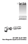
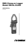
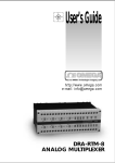
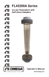
MADE
IN
USA
WARRANTY/DISCLAIMER
OMEGA ENGINEERING, INC. warrants this unit to be free of defects in materials and workmanship for a
period of 13 months from date of purchase. OMEGA Warranty adds an additional one (1) month grace
period to the normal one (1) year product warranty to cover handling and shipping time. This ensures
that OMEGA’s customers receive maximum coverage on each product.
If the unit should malfunction, it must be returned to the factory for evaluation. OMEGA’s Customer Service
Department will issue an Authorized Return (AR) number immediately upon phone or written request. Upon
examination by OMEGA, if the unit is found to be defective it will be repaired or replaced at no charge.
OMEGA’s WARRANTY does not apply to defects resulting from any action of the purchaser, including but not
limited to mishandling, improper interfacing, operation outside of design limits, improper repair, or unauthorized modification. This WARRANTY is VOID if the unit shows evidence of having been tampered with or
shows evidence of being damaged as a result of excessive corrosion; or current, heat, moisture or vibration;
improper specification; misapplication; misuse or other operating conditions outside of OMEGA’s control.
Components which wear are not warranted, including but not limited to contact points, fuses, and triacs.
OMEGA is pleased to offer suggestions on the use of its various products. However, OMEGA neither
assumes responsibility for any omissions or errors nor assumes liability for any damages that result
from the use of its products in accordance with information provided by OMEGA, either verbal or written. OMEGA warrants only that the parts manufactured by it will be as specified and free of defects.
OMEGA MAKES NO OTHER WARRANTIES OR REPRESENTATIONS OF ANY KIND WHATS0EVER,
EXPRESSED OR IMPLIED, EXCEPT THAT OF TITLE, AND ALL IMPLIED WARRANTIES INCLUDING ANY
WARRANTY OF MERCHANTABILITY AND FITNESS FOR A PARTICULAR PURPOSE ARE HEREBY DISCLAIMED. LIMITATION OF LIABILITY: The remedies of purchaser set forth herein are exclusive and the
total liability of OMEGA with respect to this order, whether based on contract, warranty, negligence,
indemnification, strict liability or otherwise, shall not exceed the purchase price of the component
upon which liability is based. In no event shall OMEGA be liable for consequential, incidental or special damages.
CONDITIONS: Equipment sold by OMEGA is not intended to be used, nor shall it be used: (1) as a “Basic
Component” under 10 CFR 21 (NRC), used in or with any nuclear installation or activity; or (2) in medical
applications or used on humans. Should any Product(s) be used in or with any nuclear installation or activity,
medical application, used on humans, or misused in any way, OMEGA assumes no responsibility as set forth
in our basic WARRANTY / DISCLAIMER language, and additionally, purchaser will indemnify OMEGA and
hold OMEGA harmless from any liability or damage whatsoever arising out of the use of the Product(s) in
such a manner.
RETURN REQUESTS / INQUIRIES
Direct all warranty and repair requests/inquiries to the OMEGA Customer Service
Department. BEFORE RETURNING ANY PRODUCT(S) TO OMEGA, PURCHASER MUST
OBTAIN AN AUTHORIZED RETURN (AR) NUMBER FROM OMEGA’S CUSTOMER SERVICE
DEPARTMENT (IN ORDER TO AVOID PROCESSING DELAYS). The assigned AR number
should then be marked on the outside of the return package and on any correspondence.
The purchaser is responsible for shipping charges, freight, insurance and proper packaging
to prevent breakage in transit.
FOR WARRANTY RETURNS, please have
FOR NON-WARRANTY REPAIRS, consult
the following information available BEFORE
OMEGA for current repair charges. Have
contacting OMEGA:
the following information available
BEFORE contacting OMEGA:
1. P.O. number under which the product
was PURCHASED,
1. P.O. number to cover the COST
of the repair,
2. Model and serial number of the product
under warranty, and
2. Model and serial number of product, and
3. Repair instructions and/or specific
3. Repair instructions and/or specific
problems relative to the product.
problems relative to the product.
OMEGA’s policy is to make running changes, not model changes, whenever an improvement is possible.
This affords our customers the latest in technology and engineering.
OMEGA is a registered trademark of OMEGA ENGINEERING, INC.
© Copyright 1996 OMEGA ENGINEERING, INC. All rights reserved. This document may not be copied,
photocopied, reproduced, translated, or reduced to any electronic medium or machine-readable form, in whole or
in part, without prior written consent of OMEGA ENGINEERING, INC.
USA:
ISO 9001 Certified
Canada:
omega.com
®
®
OMEGAnet On-Line Service
http://www.omega.com
Internet e-mail
[email protected]
SM
Servicing North America:
One Omega Drive, Box 4047
Stamford, CT 06907-0047
Tel: (203) 359-1660
e-mail: [email protected]
FAX: (203) 359-7700
976 Bergar
Laval (Quebec) H7L 5A1
Tel: (514) 856-6928
e-mail: [email protected]
FAX: (514) 856-6886
For immediate technical or application assistance:
USA and Canada:
Mexico and
Latin America:
Sales Service: 1-800-826-6342 / 1-800-TC-OMEGASM
Customer Service: 1-800-622-2378 / 1-800-622-BESTSM
Engineering Service: 1-800-872-9436 / 1-800-USA-WHENSM
TELEX: 996404 EASYLINK: 62968934 CABLE: OMEGA
Tel: (95) 800-TC-OMEGASM
En Espan˜ol: (203) 359-1660 ext: 2203
FAX: (95) 203-359-7807
e-mail: [email protected]
Servicing Europe:
Benelux:
Postbus 8034, 1180 LA Amstelveen, The Netherlands
Tel: (31) 20 6418405
FAX: (31) 20 6434643
Toll Free in Benelux: 06 0993344
e-mail: [email protected]
9, rue Denis Papin, 78190 Trappes
Tel: (33) 130-621-400
Toll Free in France: 0800-4-06342
e-mail: [email protected]
France:
Ostravska 767, 733 01 Karvina
Tel: 42 (69) 6311899
e-mail: [email protected]
Czech Republic:
FAX: 42 (69) 6311114
FAX: (33) 130-699-120
Germany/Austria: Daimlerstrasse 26, D-75392 Deckenpfronn, Germany
Tel: 49 (07056) 3017
FAX: 49 (07056) 8540
Toll Free in Germany: 0130 11 21 66
e-mail: [email protected]
United Kingdom:
ISO 9002 Certified
25 Swannington Road,
P.O. Box 7, Omega Drive,
Broughton Astley, Leicestershire,
Irlam, Manchester,
LE9 6TU, England
M44 5EX, England
Tel: 44 (1455) 285520
Tel: 44 (161) 777-6611
FAX: 44 (1455) 283912
FAX: 44 (161) 777-6622
Toll Free in England: 0800-488-488
e-mail: [email protected]
It is the policy of OMEGA to comply with all worldwide safety and EMC/EMI regulations that apply. OMEGA is constantly
pursuing certification of its products to the European New Approach Directives. OMEGA will add the CE mark to every
appropriate device upon certification.
The information contained in this document is believed to be correct but OMEGA Engineering, Inc. accepts no liability for any errors it contains, and reserves the right to alter specifications without notice.
WARNING: These products are not designed for use in, and should not be used for, patient connected applications.
(-)
.7"
LVH-200 Series
NO
(17mm)
Horizontal Mini-Float Level Switch
(+)
NC
M-4047 / 0304
Metering & Control Instrumentation
Refractometers
Pumps & Tubing
Air, Soil & Water Monitors
Industrial Water & Wastewater Treatment
pH, Conductivity & Dissolved Oxygen Instruments
REED
Heating Cable
Cartridge & Strip Heaters
Immersion & Band Heaters
Flexible Heaters
Laboratory Heaters
1.4" (36mm)
1/2" NPT
䡺
⻬
䡺
⻬
䡺
⻬
䡺
⻬
䡺
⻬
䡺
⻬
ENVIRONMENTAL
MONITORING AND CONTROL
䡺
⻬
䡺
⻬
䡺
⻬
䡺
⻬
䡺
⻬
4.5" (114mm)
2.9" (73mm)
2.4" (61mm)
2’ Cable (60cm)
LVH-200 series
Dimensions:
HEATERS
䡺
⻬
䡺
⻬
䡺
⻬
䡺
⻬
䡺
⻬
Data Acquisition & Engineering Software
Communications-Based Acquisition Systems
Plug-in Cards for Apple, IBM & Compatibles
Datalogging Systems
Recorders, Printers & Plotters
Pressure rating:
Probe material:
Mounting threads:
Cable length
CE Compliance:
DATA ACQUISITION
䡺
⻬
䡺
⻬
䡺
⻬
䡺
⻬
pH Electrodes, Testers & Accessories
Benchtop/Laboratory Meters
Controllers, Calibrators, Simulators & Pumps
Industrial pH & Conductivity Equipment
pH/CONDUCTIVITY
䡺
⻬
䡺
⻬
䡺
⻬
䡺
⻬
http://www.omega.com
e-mail: [email protected]
Rotameters, Gas Mass Flowmeters & Flow Computers
Air Velocity Indicators
Turbine/Paddlewheel Systems
Totalizers & Batch Controllers
FLOW/LEVEL
䡺
⻬
䡺
⻬
䡺
⻬
䡺
⻬
®
Transducers & Strain Gauges
Load Cells & Pressure Gauges
Displacement Transducers
Instrumentation & Accessories
Reed output:
Temperature rating:
Accuracy:
Repeatability:
Extreme orientation:
Specific gravity:
Reed type:
Reed voltage:
PRESSURE, STRAIN AND FORCE
䡺
⻬ Thermocouple, RTD & Thermistor Probes,
Connectors, Panels & Assemblies
䡺
⻬ Wire: Thermocouple, RTD & Thermistor
䡺
⻬ Calibrators & Ice Point References
䡺
⻬ Recorders, Controllers & Process Monitors
䡺
⻬ Infrared Pyrometers
± 5 mm in water
± 2 mm in water
± 20° from horizontal
0.55 minimum
Dry contact SPST
120/240, 0-30 VDC @ 20 VA
(CE: 30 Vrms and 42.2 V peak or 60 Vdc)
Selectable NO or NC
F: -40° to 225°
C: -40° to 107.2°
100 psi
Polypropylene (PP)
1/2" NPT
2 ft. (61 cm), 2-wire, 22 AWG
EN 60730
VA
Volts
Amps AC
Amps DC
20
0-30
0.4
0.3
120
0.17
0.13
240
0.08
0.06
Switch Ratings
- Maximum Resistive Load -
Specifications:
TEMPERATURE
Where Do I Find Everything I Need for
Process Measurement and Control?
OMEGA…Of Course!
User’s Guide
Step One
SPECIFICATIONS
SAFETY PRECAUTIONS
Step Two
INSTALLATION
ELECTRICAL
WIRING
Step Three
Step Four
Step Five
About this Manual:
Through Wall Installation:
Signal Outputs (Reed Switch):
Wiring to a OMEGA ENGINEERING Controller:
PLEASE READ THE ENTIRE MANUAL PRIOR TO
INSTALLING OR USING THIS PRODUCT. This manual
includes information on all models of horizontal mini-float level
switches from OMEGA ENGINEERING, LVH-200 series. Please
refer to the part number located on the switch label to verify the
exact model which you have purchased.
OMEGA ENGINEERING’s LVH-200 series sensors may be installed
through the side wall of a tank. The LVH-200 series has dual male
1/2" NPT threads for installation from the outside of the tank in or the
inside of the tank out. If the LVH-200 series is installed in the
Outside-In method, then the outer threads may be used for connection
Normally Open Operation: Orientate the switch such that float swings
down when the switch is dry. In the dry state, the float rests in the
lowest position and the circuit is open.
OMEGA ENGINEERING controllers have a built-in 13.5 VDC
power supply which provides power to all of OMEGA
ENGINEERING's level switches. Alternative controllers and power
supplies may also be used with the LVH-200 series switch.
LVCN-100 Series Controller
PU
T
1
User’s Responsibility for Safety:
Proper Installation and Handling:
Because this is an electrically operated device, only properly
trained staff should install and/or repair this product. Use a proper
sealant with all installations. Never overtighten the sensor within
the fitting, beyond being hand tight. Always check for leaks prior to
system startup.
Material Compatibility:
The LVH-200 series switch is available in one wetted material.
Models LVH-200 series are made of Polypropylene (PP). Make
sure that the model you have selected is compatible with the application liquid. To determine the chemical compatibility between the
sensor and its application liquids, refer to an industry reference
such as the Compass Corrosion Guide (available from Compass
Publications, phone 858-589-9636).
Temperature and Pressure:
The LVH-200 series switch is designed for use in application temperatures up to 107.2 °C, and for use at pressures up to 100 psi.
Wiring and Electrical:
The supply voltage used for the LVH-200 series should never
exceed 120/240 volts AC / 30 volts DC @ 20 VA. CE mark versions should never exceed 30 Vrms and 42.2 Vpeak or 60 VDC.
Electrical wiring of the sensor should be performed in accordance
with all applicable national, state, and local codes.
Flammable, Explosive and Hazardous Applications:
The LVH-200 series should not be used within flammable or explosive
applications. In hazardous applications, use redundant measurement
and control points, each having a different sensing technology. Refer to
the National Electric Code (NEC) for all applicable installation requirements in hazardous locations.
WARNING
IN
OMEGA ENGINEERING manufactures a wide range of liquid
level sensors and technologies. While each of these sensors is
designed to operate in a wide variety of applications, it is the user’s
responsibility to select a sensor model that is appropriate for the
application, install it properly, perform tests of the installed system,
and maintain all components. The failure to do so could result in
property damage or serious injury.
Power
Supply
GND
Maintenance:
The LVH-200 series sensor itself requires no periodic maintenance
except cleaning as required. It is the responsibility of the user to determine the appropriate maintenance schedule, based on the specific
characteristics of the application liquids.
(+)
NC
R
(-)
C
115 VAC
220 VAC
Power
Supply
NO
DELAY
Normally Closed Operation: Orientate the switch such that float rests
on top of the switch when the switch is dry. In the dry state, the float
rests on the switch and the circuit is closed.
LVCN-120/-130/-140 Series Controller
Cleaning Procedure:
1. Power: Make Sure that all power to the sensor, controller and/or
power supply is completely disconnected.
2. Sensor Removal: In all through-wall installations, make sure
that the tank is drained well below the sensor prior to removal.
Carefully, remove the sensor from the installation.
3. Cleaning the Sensor: Use a soft bristle brush and mild detergent, carefully wash the LVH-200 series sensor. Do not use harsh
abrasives such as steel wool or sandpaper, which might damage
the surface sensor. Do not use incompatible solvents which may
damage the sensor's Polypropylene plastic body.
4. Sensor Installation: Follow the appropriate steps of installation as outlined in the installation section of this manual.
Power
Supply
POWER
I N V E RT
D E L AY
-- +
As the switch becomes wet, the float becomes buoyant and circuit
opens.
I N V E RT
D E L AY
-- +
R E L AY 1
R E L AY 2
LA
INPUT1
INPUT2A
ONOFF
INPUT2B
TCH
Power
Supply
Contact Protection (Reed Switch):
When current is interrupted, the inductance of the load generates a
high frequency voltage, which appears across the switch contacts. If
the voltage is large enough, it can cause arcing. Arcing can cause the
contacts to weld to each other resulting in unreliable switching performance. It is essential to protect the circuit, by suppressing the voltage to prevent arcing.
This can be accomplished through the use of a diode for DC circuits
and a resistor-capacitor network for AC circuits.
DC Contact Protection:
Pos
Inductive Load
Orientation of the switch is critical. Make sure the switch is
positioned correctly.
Avoid installing the LVH-200 series switch in ferromagnetic
tanks. Doing so will activate the internal reed switch.
AC
As the switch becomes wet, the float becomes buoyant and circuit
closes.
to conduit.
INVERT +/-
AC
P
Neg
1N4004
AC Contact Protection:
Inductive Load
HOT
NTRL
100Ω
1/4 watt
.1 F
.600 V
Note: The above wiring is for NO operation. For NC operation, rotate
the switch 180 degrees.