1
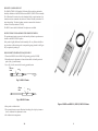
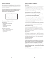
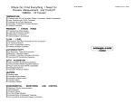
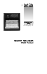
Where Do I Find Everything I Need for
Process Measurement and Control?
OMEGA…Of Course!
User’s Guide
TEMPERATURE
M
U
M
U
M
U
M
U
M
U
Thermocouple, RTD & Thermistor Probes, Connectors, Panels & Assemblies
Wire: Thermocouple, RTD & Thermistor
Calibrators & Ice Point References
Recorders, Controllers & Process Monitors
Infrared Pyrometers
PRESSURE, STRAIN AND FORCE
M
U
M
U
M
U
M
U
Transducers & Strain Gauges
Load Cells & Pressure Gauges
Displacement Transducers
Instrumentation & Accessories
®
FLOW/LEVEL
M
U
M
U
M
U
M
U
Rotameters, Gas Mass Flowmeters & Flow Computers
Air Velocity Indicators
Turbine/Paddlewheel Systems
Totalizers & Batch Controllers
http://www.omega.com
e-mail: [email protected]
pH/CONDUCTIVITY
M
U
M
U
M
U
M
U
pH Electrodes, Testers & Accessories
Benchtop/Laboratory Meters
Controllers, Calibrators, Simulators & Pumps
Industrial pH & Conductivity Equipment
DATA ACQUISITION
M
U
M
U
M
U
M
U
M
U
Data Acquisition & Engineering Software
Communications-Based Acquisition Systems
Plug-in Cards for Apple, IBM & Compatibles
Datalogging Systems
Recorders, Printers & Plotters
HEATERS
M
U
M
U
M
U
M
U
M
U
Heating Cable
Cartridge & Strip Heaters
Immersion & Band Heaters
Flexible Heaters
Laboratory Heaters
ENVIRONMENTAL
MONITORING AND CONTROL
M
U
M
U
M
U
M
U
M
U
M
U
Metering & Control Instrumentation
Refractometers
Pumps & Tubing
Air, Soil & Water Monitors
Industrial Water & Wastewater Treatment
pH, Conductivity & Dissolved Oxygen Instruments
RH31
M3185/1098
Handheld Temperature/
Humidity Indicator
omega.com
WARRANTY/DISCLAIMER
TM
OMEGA®
OMEGAnet On-Line Service
http://www.omega.com
SM
Internet e-mail
[email protected]
Servicing North America:
USA:
ISO 9001 Certified
Canada:
One Omega Drive, Box 4047
Stamford, CT 06907-0047
Tel: (203) 359-1660
e-mail: [email protected]
976 Bergar
Laval (Quebec) H7L 5A1
Tel: (514) 856-6928
e-mail: [email protected]
FAX: (203) 359-7700
FAX: (514) 856-6886
For immediate technical or application assistance:
USA and Canada: Sales Service: 1-800-826-6342 / 1-800-TC-OMEGASM
Customer Service: 1-800-622-2378 / 1-800-622-BESTSM
Engineering Service: 1-800-872-9436 / 1-800-USA-WHENSM
TELEX: 996404 EASYLINK: 62968934 CABLE: OMEGA
Mexico and
Latin America:
Tel: (95) 800-TC-OMEGASM
En Espan˜ol: (203) 359-7803
FAX: (95) 203-359-7807
e-mail: [email protected]
Servicing Europe:
Benelux:
Postbus 8034, 1180 LA Amstelveen, The Netherlands
Tel: (31) 20 6418405
FAX: (31) 20 6434643
Toll Free in Benelux: 06 0993344
e-mail: [email protected]
Czech Republic:
ul. Rude armady 1868, 733 01 Karvina-Hranice, Czech Republic
Tel: 420 (69) 6311627
FAX: 420 (69) 6311114
e-mail: [email protected]
France:
9, rue Denis Papin, 78190 Trappes
Tel: (33) 130-621-400
Toll Free in France: 0800-4-06342
e-mail: [email protected]
FAX: (33) 130-699-120
Germany/Austria: Daimlerstrasse 26, D-75392 Deckenpfronn, Germany
Tel: 49 (07056) 3017
Toll Free in Germany: 0130 11 21 66
e-mail: [email protected]
FAX: 49 (07056) 8540
United Kingdom: 25 Swannington Road,
ISO 9002 Certified
P.O. Box 7, Omega Drive,
Broughton Astley, Leicestershire,
Irlam, Manchester,
LE9 6TU, England
M44 5EX, England
Tel: 44 (1455) 285520
Tel: 44 (161) 777-6611
FAX: 44 (1455) 283912
FAX: 44 (161) 777-6622
Toll Free in England: 0800-488-488
e-mail: [email protected]
It is the policy of OMEGA to comply with all worldwide safety and EMC/EMI regulations that
apply. OMEGA is constantly pursuing certification of its products to the European New Approach
Directives. OMEGA will add the CE mark to every appropriate device upon certification.
The information contained in this document is believed to be correct but OMEGA Engineering, Inc. accepts
no liability for any errors it contains, and reserves the right to alter specifications without notice.
WARNING: These products are not designed for use in, and should not be used for, patient connected applications.
OMEGA ENGINEERING, INC. warrants this unit to be free of defects in materials and
workmanship for a period of 25 months from date of purchase. OMEGA Warranty adds an
additional one (1) month grace period to the normal two (2) year product warranty to cover
handling and shipping time. This ensures that OMEGA’s customers receive maximum
coverage on each product.
If the unit should malfunction, it must be returned to the factory for evaluation. OMEGA’s
Customer Service Department will issue an Authorized Return (AR) number immediately upon
phone or written request. Upon examination by OMEGA, if the unit is found to be defective it will
be repaired or replaced at no charge. OMEGA’s WARRANTY does not apply to defects resulting
from any action of the purchaser, including but not limited to mishandling, improper interfacing,
operation outside of design limits, improper repair, or unauthorized modification. This
WARRANTY is VOID if the unit shows evidence of having been tampered with or shows evidence
of being damaged as a result of excessive corrosion; or current, heat, moisture or vibration;
improper specification; misapplication; misuse or other operating conditions outside of
OMEGA’s control. Components which wear are not warranted, including but not limited to
contact points, fuses, and triacs.
OMEGA is pleased to offer suggestions on the use of its various products. However,
OMEGA neither assumes responsibility for any omissions or errors nor assumes liability
for any damages that result from the use of its products in accordance with information
provided by OMEGA, either verbal or written. OMEGA warrants only that the parts
manufactured by it will be as specified and free of defects. OMEGA MAKES NO OTHER
WARRANTIES OR REPRESENTATIONS OF ANY KIND WHATSOEVER, EXPRESSED OR
IMPLIED, EXCEPT THAT OF TITLE, AND ALL IMPLIED WARRANTIES INCLUDING ANY
WARRANTY OF MERCHANTABILITY AND FITNESS FOR A PARTICULAR PURPOSE ARE
HEREBY DISCLAIMED. LIMITATION OF LIABILITY: The remedies of purchaser set forth
herein are exclusive and the total liability of OMEGA with respect to this order, whether
based on contract, warranty, negligence, indemnification, strict liability or otherwise, shall
not exceed the purchase price of the component upon which liability is based. In no event
shall OMEGA be liable for consequential, incidental or special damages.
CONDITIONS: Equipment sold by OMEGA is not intended to be used, nor shall it be used: (1) as
a “Basic Component” under 10 CFR 21 (NRC), used in or with any nuclear installation or activity;
or (2) in medical applications or used on humans. Should any Product(s) be used in or with any
nuclear installation or activity, medical application, used on humans, or misused in any way,
OMEGA assumes no responsibility as set forth in our basic WARRANTY/DISCLAIMER language,
and additionally, purchaser will indemnify OMEGA and hold OMEGA harmless from any liability
or damage whatsoever arising out of the use of the Product(s) in such a manner.
RETURN REQUESTS / INQUIRIES
Direct all warranty and repair requests/inquiries to the OMEGA Customer Service Department.
BEFORE RETURNING ANY PRODUCT(S) TO OMEGA, PURCHASER MUST OBTAIN AN
AUTHORIZED RETURN (AR) NUMBER FROM OMEGA’S CUSTOMER SERVICE DEPARTMENT
(IN ORDER TO AVOID PROCESSING DELAYS). The assigned AR number should then be
marked on the outside of the return package and on any correspondence.
The purchaser is responsible for shipping charges, freight, insurance and proper packaging to
prevent breakage in transit.
FOR WARRANTY RETURNS, please have
the following information available BEFORE
contacting OMEGA:
1. P.O. number under which the product was
PURCHASED,
2. Model and serial number of the product
under warranty, and
3. Repair instructions and/or specific
problems relative to the product.
FOR NON-WARRANTY REPAIRS, consult
OMEGA for current repair charges. Have the
following information available BEFORE
contacting OMEGA:
1. P.O. number to cover the COST
of the repair,
2. Model and serial number of product, and
3. Repair instructions and/or specific problems
relative to the product.
OMEGA’s policy is to make running changes, not model changes, whenever an improvement is possible.
This affords our customers the latest in technology and engineering.
OMEGA is a registered trademark of OMEGA ENGINEERING, INC.
© Copyright 1996 OMEGA ENGINEERING, INC. All rights reserved. This document may not be copied, photocopied,
reproduced, translated, or reduced to any electronic medium or machine-readable form, in whole or in part, without
prior written consent of OMEGA ENGINEERING, INC.
NOTES
15
TABLE OF CONTENTS
RH31 Humidity/Temperature Meter
SECTION 1
INTRODUCTION . . . . . . . . . . . . . . . . . . . . . . . . . . . . . . . . . . . . 1
SECTION 2
UNPACKING . . . . . . . . . . . . . . . . . . . . . . . . . . . . . . . . . . . . . . . . 3
SECTION 3
3.1
3.2
3.3
ASSEMBLY . . . . . . . . . . . . . . . . . . . . . . . . . . . . . . . . . . . . . . . . . .
Battery Installation . . . . . . . . . . . . . . . . . . . . . . . . . . . . . . . . . . . .
RH31 Indicator Assembly . . . . . . . . . . . . . . . . . . . . . . . . . . . . . .
How to Switch From ˚ F to ˚ C . . . . . . . . . . . . . . . . . . . . . . . . . .
SECTION 4
4.1
4.2
4.3
OPERATING INSTRUCTIONS . . . . . . . . . . . . . . . . . . . . . . . .. 6
Display Codes . . . . . . . . . . . . . . . . . . . . . . . . . . . . . . . . . . . . . . . . 6
RS232 Communications . . . . . . . . . . . . . . . . . . . . . . . . . . . . . . . 8
Key Operations . . . . . . . . . . . . . . . . . . . . . . . . . . . . . . . . . . . . . . . 10
SECTION 5
HUMIDITY CALIBRATION . . . . . . . . . . . . . . . . . . . . . . . . . . . 12
SECTION 6
SPECIFICATIONS . . . . . . . . . . . . . . . . . . . . . . . . . . . . . . . . . . . . 13
i
5
5
5
5
SECTION 1 INTRODUCTION
SECTION 6 SPECIFICATIONS
The OMEGA RH31 Handheld Temperature/Humidity Indicator has broad
applications in air conditioning services, food management, process engineering,
and many uses in experimental and research facilities.
RH31 METER
Measuring range:
®
The built-in digital display is accurate to ±0.6˚ F (0.3˚ C) and ±3% RH, and reads
out in either degrees F/C.
Three probe types are available for use with the RH31 and all are interchangeable
through a connector located on the RH31 Indicator:
RH31-1 General Purpose Probe for Laboratory and Warehouses
RH31-2 Thin Type Probe for Tanks and Narrow Gaps
RH31-3 Remote Mounted Probe with Cable
The ultra sensitive composite sensor element in the probes is composed of a
temperature and humidity sensor formed into a single unit. The humidity sensor
is an electrostatic capacitance type polymer-film, and the temperature sensor is a
platinum resistance RTD.
A calibration kit (part number RH30-CAL) is also available for recalibrating the
RH31 Indicator and RH31-1 General Purpose Probe.
Obtain new sensor, if temperature/humidity sensor has become defective. No
adjustment is necessary after exchange, because the sensor is interchangeable.
If the response time is delayed in the general type sensor, remove the cap from
the sensor tip, and remove the filter. (Screw in the cap as before after removing
the filter.) In this case, the sensor is apt to be contaminated with dust or the like,
and its service life may shorten.
The battery assembled at the delivery time from the factory is used for test so that
its life may be shorter than the nominal value.
Power auto-off function
A power auto-off function is provided and the battery life is longer than 400
hours in continuous use at normal temperature.
The RH31-RS232 has a memory function and is also able to collect up to 1500
points of data (temp., humidity). The measuring interval is 10 minutes.
Temperature-humidity sensor exchange
The temperature-humidity sensor is interchangeable, and it can easily be
replaced, if it has been broken or it has deteriorated.
Handling of temperature-humidity sensor
Handle this precise unit carefully so as not to drop or strike it, otherwise a trouble
may occur. This unit is not water-proof. Don’t dip it into water or moisten it.
1
Temperature: -10 to 60˚ C
Relative humidity: 0 to 100% RH
Accuracy rating:
Temperature: ±(0.1% of measured value +0.2˚ C)
Relative humidity: ±(0.1% of measured value +0.2% RH)
Dew-point temperature: ±1.0˚ C
Wet-bulb temperature: ±0.8˚ C
(at temperature 25˚ C and relative humidity 50% RH)
Temperature
Temperature: ±(0.2% of measured value +0.1˚ C)
coefficient (per 10˚ C): Relative humidity: ±(0.2% of measured value +0.1% RH)
Display:
31/2 digits LCD (Liquid crystal) digital display
Temperature, relative humidity, dew-point temperature,
wet-bulb temperature, unit, battery shortage mark
Resolution:
Temperature: 0.1˚ C/0.1˚ F
Relative humidity: 0.1% RH
Memory function:
Data: 1500 data each of temperature and humidity
Content: Temperature, humidity
Measurement Time Interval: 10-minute
Communications
RS-232C
Interface:
(with communication cable)
Working
temperature range:
0 to 50˚ C (32 to 122˚ F)
Working
humidity range:
0 to 85% RH (no dew condensation is allowed)
Power Voltage:
Exclusive lithium battery 1 piece (7.2 Vdc)
Battery life:
Approx. 400 hours
(at normal temperature and humidity)
Weight:
Approx. 180 g (6.3 oz) (without memory function)
Approx. 190 g (6.7 oz) (with memory function)
RH31 SENSORS
Measuring range:
Temperature: -10 to 60 ˚ C (14 to 140˚ F)
Relative humidity: 0 to 100% RH
Accuracy rating:
Temperature: ±0.15˚ C (at 0˚ C), ±(0.15+0.002[t])˚ C,
t: Measured temperature (˚ C)
Relative humidity: ±3% RH (at 25˚ C, 0 to 90% RH)
Temperature
coefficient:
Relative humidity: ±1% RH (Reference 25˚ C, per 10˚ C)
Response:
Without filter: Approx. 1 minute (90% response)
With filter: Approx. 3 minutes (90% response)
Sensor element:
Temperature: Platinum resistance thermometer (JIS Class A)
Humidity: Capacitance type high polymer film
Cable length:
Standard 1m (3'), Maximum 5m (16')
Weight (with 1m
RH31-1: Approx. 60 g (2.1 oz)
of cable):
RH31-2: Approx. 70 g (2.5 oz)
RH31-3: Approx. 100 g (3.5 oz)
14
HUMIDITY CALIBRATION KIT
The OMEGA® RH30-CAL Humidity Calibration Kit is needed to perform the
humidity calibration of the RH31 Indicator and RH31-1/RH31-2 Probe assembly.
The Calibration Kit consists of two salt chambers held in a styrofoam base. One
chamber contains a saturated salt solution of Lithium Chloride (to simulate 11%
relative humidity). The other chamber contains a saturated salt solution of
Sodium Chloride (to simulate 75% RH).
The RH31-3 cannot be field calibrated. No adapters are available.
INSTRUCTIONS TO DISASSEMBLE THE HUMIDITY PROBES
The potentiometer (pots) necessary for the humidity calibration procedures are
located in the RH31-1/RH31-2 probes.
Each probe is slightly different, thus disassembly will vary. Perform the following procedures while referring to the corresponding steps pictured in the Figure
for your particular probe type.
RH31 HUMIDITY/TEMPERATURE ADJUSTMENT
1. Please have RH30 Kit which OMEGA Engineering provide (30% RH).
2. Potential meter for adjustment is located about middle of handle portion of
probe. (Only 1 potential meter)
3. As on Fig. 3 and 4, remove label covering potential meter.
Remove
Label
VR
Fig. 3. RH31-1 Probe
Remove
Label
VR
Fig. 4. RH31-2 Probe
Figure 1. RH31 and RH31-1, RH31-2, RH31-2 Probes
4. Enter probe to calibration kit.
5. Turn potential meter to meet calibration kit reading. Once display is same or
close to calibration kit, adjustment is done.
6. No calibration for temperature.
13
2
SECTION 2 UNPACKING
SECTION 5 HUMIDITY CALIBRATION
Remove the packing list and verify that all equipment has been received. If there
are any questions about the shipment, please call the OMEGA Customer Service
Department at 1-800-622-2378.
PRECAUTIONS
Due to its design, and ease of access, the humidity sensor must be handled with
care. AVOID ANY CONTACT with fingers, atmosphere, or products which
could be harmful to the sensor. The sensor must not come in contact with dirt or
other foreign material. Incorrect readings can be caused by build-up of material,
which can increase or decrease the RH reading.
Upon receipt of shipment, inspect the container and equipment for any signs of
damage. Take particular note of any evidence of rough handling in transit.
Immediately report any damage to the shipping agent.
During measurements, the following precautions should be taken:
NOTE:
The carrier will not honor any claims unless all shipping
material is saved for their examination. After examining
and removing contents, save packing material and carton
in the event reshipment is necessary.
Please note that the following items are in the box:
RH31 INDICATOR:
RH31 Temperature/Humidity Indicator
9 volt Battery
Transparent vinyl case for Indicator
Operator’s Manual
RH31 PROBES (refer to Figure 2):
RH30-1, -2, -3, Humidity/Temperature Probe
Plastic Bag to hold probe assembly
Operator’s Manual
1. When the temperature, at the location being measured, changes drastically,
allow at least 10 minutes for the measurement to stabilize.
2. The sensor response will vary greatly depending on the air flow in the vicinity
being measured, the heat capacity of materials surrounding the probe, and the
thermal conductivity. Alllowing for the response time of 30 seconds or so,
keep the probe at a distance from the body, when the probe is held in ones
hand, to eliminate the effects of body heat.
3. Always turn the unit OFF after measurements are completed. When the meter
is not in use for extended periods of time, remove and store the battery.
HUMIDITY SENSOR CLEANING
Use no solvents stronger than DISTILLED WATER to clean the sensors. If
necessary, rinse the sensors with distilled water, being careful not to touch it
with your fingers. After rinsing, the sensors should air dry for at least 24 hours
(prefereably over an air flow register).
DISPLAY CODES
-OVER: Measured values are displayed on the 31/2 digit LCD. For temperatures
over 212˚ F (100˚ C) and humidity over 99.9%, the message “OVER” is displayed.
-BATT: When the battery is low, the message “BATT” appears on the display
and the batttery must be replaced.
HUMIDITY CALIBRATION
The RH31 Indicator and probes are calibrated at the factory and do not usually
need to be recalibrated. The warranty is void if the unit is tampered with while
still under warranty. Contact OMEGA Engineering for service information.
The following procedures are necessary only if the unit is operating out of specification and is no longer under warranty. These procedures should be performed
by a qualified technician.
Only the RH31-1 general purpose probe & RH31-2 can be field calibrated.
3
12
Figure 2. Probe Assemblies for the RH31
Figure 1. RH31 Indicator
11
4
SECTION 3 ASSEMBLY
3.1 Battery Installation
4.3 Key Operation
BATTERY EXCHANGE METHOD
1. How to open the case
The case can be opened by removing two screws on the rear panel of the case.
In this case, the case can be opened easily be pulling the hand strap in the open
direction, while pressing the upper case.
2. How to remove the battery
Insert a screwdriver to the bottom of the battery connector while holding the
battery connector by fingers, and disconnect the connector by pushing it upward.
3. Battery exchange
Connect the battery connector to the connector on the PC Board. In this case, a
confirmation chime sounds to show the end of the exchange.
Never disassemble, short, charge, throw into a fire, or heat the used battery
nor directly solder it to the battery body, otherwise a rupture accident or an
electrolyte leak failure may occur.
4. How to close the case
Insert the battery cord to the guide of the upper case without protruding it out of
the case. Mount the hand strap.
Fit the upper and lower cases to each other and fasten two screws.
3.2 RH31 Indicator Assembly
Slide the RH31 indicator into the vinyl case provided in order to protect the case
during use. Plug in the probe that is best suited for your application (see Figure 2
above for probe selection). The temperature/humidity probes are plugged into
the socket located on the top of the indicator. Be sure to line up the “keys” on
each connector before plugging in the probe.
3.3 How To Switch From ˚F/˚C
1. Remove 2 back cover screws.
2. Jumper pins 1 & 2 for ˚C, pins 2 & 3 for ˚ F.
3. Put back lower case and tighten screws.
Cover
Screws
˚C
5
Names of keys Contents
ON-OFF The power supply is turned on by pressing this key once and turned
off by pressing this key again.
A confirmation chime sounds after turning on the power supply, and the power
supply turns off automatically after about 3 minutes.
For canceling the auto off function, press [ON-OFF] key together with [CLEAR]
key.
A confirmation chime sounds three times.
For turning off the power supply, press [ON-OFF] key.
•CLEAR By pressing this key, a confirmation chime sounds, the display setting
functions (hold, humidity operation selection) are canceled, and the unit returns
to the initial condition.
When the memory function is provided, (1) data collection is stopped by pressing this key halfway during data collection (2) data readout is stopped by pressing this key halfway during data readout, and also (3) the unit is reset to the last
settting by pressing this key halfway during the time setting.
•HOLD The measured values of temperature and humidity are held by pressing this key and the unit is set to the measuring condition (the hold condition is
canceled) by pressing this key once more.
During the hold of measured values, ˚ C(˚ F) flickers.
•SEL The indicating value is switched in the order of [relative humidity →
dew point → wet-bulb temperature].
Relative humidity: %RH
Dew point: ˚C(˚ F)
Wet-bulb temperature: ˚C(˚ F) flickering
•READ Press this key for advancing the numeric stepwise when setting the
present time or data collection time.
Press this key when transmitting collection data to the personal computer.
•WRITE Press this key for switching the setting items such as year, month,
day, hour, and minute when setting the present time and data collection time.
TROUBLESHOOTING
Symptoms Check contents
No display appears – Problem 1
Are the indicator and temperature-humidity sensor connected to each other
securely?– Check
Has the battery life come to an end? – Check
Is the battery set correctly? – Check
Display remains unchanged – Problem 2
Is the [HOLD] key pressed? (˚ C (˚ F) flickers in this case) – Check
Measured values are abnormal – Problem 3
[Is the unit correct?] – Check
Bar display appears in the upper column. – Problem 4
[Over-range]
Bar display appears in the lower column – Problem 5
[Under-range]
˚F
10
4. Sample program
Prepare a data file in advance.
(1) In case of N88BASIC (A hard disc is used)
60 “232-C CIRCUIT”
110 ’DATA STORAGE
(2) In case of N88BASIC (a floppy disc is used)
80 “232-C Circuit”
100 FOR A = 0 TO 50000!
‘’SELECT THE FINAL VALUE TO CONFORM TO PC.
200 DATA STORAGE
220 IF 1=0 THEN PRINT
‘’COMMUNICATION IS IMPOSSIBLE”: END
Communication Protocol for RH31-RS232C
Start-Stop System
3 line system
Transmission Speed
Start bit
Data Length
Stop bit
Character code
Data transmission
Procedure
: Talk only
: 1200 bps
: 1 bit
: 8 bits
: 1 bit
: ASCII code
: Non-procedure
RH31-RS232C does not have any communication formats
because this output measuring data at a stroke.
5. Maintenance
For cleaning it, wipe it off with a dry soft cloth without fail.
Never use benzene, thinner, or the like, otherwise a color change, deformation,
deterioration of sensor, or other troubles may occur.
Storage of temperature-humidity sensor
For storing the sensor for a long time, seal it into a clean vinyl bag together with
a desiccant like silica gel, and store it at a cool dark palce.
Filter exchange
The general type temperature-humidity sensor (RH31-1) filter can be replaced if
it has become dirty. Remove the cap from the sensor tip by turning it counterclockwise, and draw out the filter carefully to as not to damage the sensor.
Insert new filter with due care so as not to damage the sensor, and screw in the cap.
Measurement in a very wet atmosphere and moistening
In a very wet atmosphere of higher than 90%RH, dew may be formed due to
a slight drop of the ambient temperature.
Even if dew is formed on the humidity sensor, no characteristic change occurs.
However, it may cause an abnormal measured value. If dew has been formed on
the sensor, dry it at 60 to 70˚ C for about one hour in a thermostatic oven or the
like. Don’t dry it up abruptly. It takes longer than 12 hours to dry up the sensor
at room temperature.
SECTION 4 OPERATING INSTRUCTIONS
4.1 Display Codes
(1) Connection joint:
Connect the exclusive temperature-humidity sensor to top of unit.
(2) AM/PM indication Note):
Indicated when the present time or preset data collection time is set.
(3) Battery shortage indication:
The battery shortage mark lights when the battery life comes to an end.
(4) [ON-OFF] key:
Turns on and off the power supply.
The power auto-off function is reset by [CLEAR] key + [ON-OFF] key.
(5) [HOLD] key:
Press this key when holding a measured value.
(6) [READ] key Note):
Press this key when transmitting data to a personal computer.
(7) [WRITE] key Note):
Press this key when setting the preset time or preset data collection time or when
transmitting date to a personal computer.
(8) Measured temperature value and unit:
Indicates the measured temperature value and unit (˚ C or ˚ F).
(9) Measured humidity value and unit:
Indicates the measured humidity value and unit (%RH (relative humidity) ˚C
(˚ F) (dew point), ˚ C (˚ F) flickering (wet-bulb temperature).
(10) [CLEAR] key:
Press this key when resetting the indication setting (hold, humidity unit
selection).
(11) Unit indication mark:
Indicates the displayed humidity measuring unit.
%RH: relative humidity ˚C (˚F) (DP)lighting: Dew point ˚C (˚ F)(WB) flickering:
Wet-bulb temperature.
(12) [SEL] key:
Press this key when changing the measuring unit of humidity.
OPERATION METHOD
Preparation for measurement
1. Assembly of battery
The battery is assembled at the delivery time from the factor and it is employable
as it is. However, the battery life is not guaranteed due to the use for test. If the
battery shortage mark is indicated, replace the battery.
For the method of replacing the battery, refer to [Maintenance].
2. Sensor connection
Connect the sensor securely to the circular connector at the upper part of the
indicator, while taking care of the sensor correction direction.
9
6
Measurement
Display appears by pressing the [ON-OFF] key after the unit has been ready for
measurement.
The power supply turns off automatically about 3 minutes after the last key
operation has been finished. For canceling the auto off function, press [ON-OFF]
key together with the [CLEAR] key when the power supply is turned off. In this
case, a confirmation chime sounds three times.
After several seconds, the sensor number is displayed as shown in (2).
(Note) The display number may change from 01 to 09 according to the kinds of
sensor, etc. However, it does not affect any measurement at all.
After several seconds, a measured temperature value is indicated in the upper
column, while a measured humidity value is indicated in the lower column as
shown in (3).
The initial value of the humidity unit shows a relative humidity. It changes in the
order of %RH (relative humidity) → ˚ C (˚ F) (dew point) → ˚ C (˚ F)flickering
(wet-bulb temperature) → %RH → ...
(4) shows an example of the dew point indication, while (5) shows an example of
the wet-bulb temperature indication. This display turns to %RH indication when
pressing the [CLEAR] key.
For finishing the measurement, press [ON-OFF] key. The power off function is
set automatically when turning on the power supply next.
KEY OPERATION METHOD WHEN THE UNIT IS
PROVIDED WITH A MEMORY FUNCTION
Data Collection
1. Present time setting
Display flickers when pressing [WRITE] key.
[Year] flickers when pressing [READ] key and it advances stepwise, each time
[READ] key is pressed once.
When a desired [Year] has been displayed, press the [WRITE] key to define the
year.
For [Month], [Day], [Hour], and [Minute], press [READ] key until they reach a
desired value respectively and press [WRITE] key to define them.
By pressing [CLEAR] key, the setting returns to the last one.
2. Setting of the data collection start time
Set the data collection start time.
After setting the present time, display flickers.
[Year] flickers when pressing [READ] key and it advances stepwise, each time
[READ] key is pressed once.
When a desired [Year] has been displayed, press the [WRITE] key to define the
year.
For [Month], [Day], [Hour], and [Minute], press [READ] key until they reach a
desired value respectively and press [WRITE] key to define them.
By pressing [CLEAR] key, the setting returns to the last one. Set the reservation
time ahead from the present time without fail.
7
3. Collection and stop
When the reservation time has been set, the confirmation chime sounds.
After about 3 minutes, the display appears, and the data collection is started
from the reservation time.
For stopping the data collection, press [ON-OFF] key to display the measured
value, and then, press the [CLEAR] key.
When the data collection start time has already been set, data collection is
executed at the preset time even if the power supply is turned off.
4. Memory
Data can be collected by [temperature, humidity] x 1500.
Data collection is stopped when the memory capacity is fully filled with data.
The measuring interval is fixed to 10 minutes.
If data collection was interrupted halfway, past data are valid, but subsequent
old data become invalid. (Preset 1000 data are valid, but the 500 data collected
last become invalid.)
4.2 RS232 Communications
DATA READ
1. Connection to personal computer
Prepare an NEC PC98 series personal computer.
Connect RH31 to the personal computer by using the attached cable.
Attached RS-232C cable
Personal computer
2. Setting of personal computer
Set RS-232C of the personal computer as follows.
Transfer speed: 1200 bps
Character length: 7 bits Parity: None
Stop bit: 2 bits X parameter: None
3. Data read and stop
Data are transmitted to the personal computer by pressing the [READ] key.
In this case, data are transmitted in the units of humidity selected by [SEL] key.
Data read is stopped by pressing [CLEAR] key.
Read data (text format) are as shown below
Specify the delimiters of data by comma [,], and use the table calculation software (EXCEL, Lotus123, etc. for example). Measured values are described on the
cell numerically.
a. Collection interval b. number
c. Temperature
d. Humidity
e. Measurement start year, month, day, and hour
%RH: Relative humidity C(F): Dew point
$C($F): Wet-bulb temperature
8