1
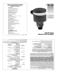
Where Do I Find Everything I Need for
Process Measurement and Control?
OMEGA ... Of Course!
TEMPERATURE
3
o
o
3
o
3
o
3
3
o
Thermocouple, RTD & Thermistor Probes, Connectors, Panels & Assemblies
Wire: Thermocouple, RTD & Thermistor
Calibrators & Ice Point References
Recorders, Controllers & Process Monitors
Infrared Pyrometers
PRESSURE
/
STRAIN
3 Transducers & Strain Gauges
o
o
3 Load Cells & Pressure Gauges
o
3 Displacement Transducers
o
3 Instrumentation & Accessories
FLOW /
3
o
o
3
o
3
o
3
FORCE
LEVEL
Rotameters, Gas Mass Flowmeters & Flow Computers
Air Velocity Indicators
Turbine / Paddlewheel Systems
Totalizers & Batch Controllers
pH/CONDUCTIVITY
3 pH Electrodes, Testers & Accessories
o
o
3 Benchtop / Laboratory Meters
3 Controllers, Calibrators, Simulators & Pumps
o
o
3 Industrial pH & Conductivity Equipment
DATA ACQUISITION
3 Data Acquisition & Engineering Software
o
3 Communications-Based Acquisition Systems
o
o
3 Plug-in Cards for Apple, IBM & Compatibles
o
3 Datalogging Systems
o
3 Recorders, Printers & Plotters
HEATERS
3
o
o
3
o
3
o
3
o
3
Heating Cable
Cartridge & Strip Heaters
Immersion & Band Heaters
Flexible Heaters
Laboratory Heaters
ENVIRONMENTAL
3
o
o
3
o
3
o
3
o
3
3
o
MONITORING
AND
Metering & Control Instrumentation
Refractometers
Pumps & Tubing
Air, Soil & Water Monitors
Industrial Water & Wastewater Treatment
pH, Conductivity & Dissolved Oxygen Instruments
CONTROL
M-3479/0899
99-MAN 100179 v1 09/99
OL
ON
DC
ZERO
http:/www.omega.com
e-mail:
[email protected]
! 600V CAT III - 1500A
150A
1500A
OFF
OUTPUT:
1500 A: 1 mV/A
150 A: 10 mV/A
HHM76
AC/DC CURRENT PROBE
®
Model HHM73
Model HHM76
AC/DC Oscilloscope
Current Probes
WARRANTY/DISCLAIMER
OMEGA ENGINEERING, INC. warrants this unit to be free of defects in materials and workmanship for
a period of 13 months from date of purchase. OMEGA Warranty adds an additional one (1) month
grace period to the normal one (1) year product warranty to cover handling and shipping time. This
ensures that OMEGA's customers receive maximum coverage on each product.
If the unit should malfunction, it must be returned to the factory for evaluation. OMEGA's Customer
Service Department will issue an Authorized Return (AR) number immediately upon phone or written
request. Upon examination by OMEGA, if the unit is found to be defective it will be repaired or replaced
at no charge. OMEGA's WARRANTY does not apply to defects resulting from any action of the
purchaser, including but not limited to mishandling, improper interfacing, operation outside of design
limits, improper repair, or unauthorized modification. This WARRANTY is VOID if the unit shows
evidence of having been tampered with or shows evidence of being damaged as a result of excessive
corrosion; or current, heat, moisture or vibration; improper specification; misapplication; misuse or other
operating conditions outside of OMEGA's control. Components which wear are not warranted, including
but not limited to contact points, fuses, and triacs.
OMEGA is pleased to offer suggestions on the use of its various products. However, OMEGA
neither assumes responsibility for any omissions or errors nor assumes liability for any
damages that result from the use of its products in accordance with information provided by
OMEGA, either verbal or written. OMEGA warrants only that the parts manufactured by it will be
as specified and free of defects. OMEGA MAKES NO OTHER WARRANTIES OR
REPRESENTATIONS OF ANY KIND WHATSOEVER, EXPRESSED OR IMPLIED, EXCEPT THAT OF
TITLE, AND ALL IMPLIED WARRANTIES INCLUDING ANY WARRANTY OF MERCHANTABILITY
AND FITNESS FOR A PARTICULAR PURPOSE ARE HEREBY DISCLAIMED. LIMITATION OF
LIABILITY: The remedies of purchaser set forth herein are exclusive and the total liability of
OMEGA with respect to this order, whether based on contract, warranty, negligence,
indemnification, strict liability or otherwise, shall not exceed the purchase price of the
component upon which liability is based. In no event shall OMEGA be liable for consequential,
incidental or special damages.
CONDITIONS: Equipment sold by OMEGA is not intended to be used, nor shall it be used: (1) as a
"Basic Component" under 10 CFR 21 (NRC), used in or with any nuclear installation or activity; or (2) in
medical applications or used on humans. Should any Product(s) be used in or with any nuclear
installation or activity, medical application, used on humans, or misused in any way, OMEGA assumes
no responsibility as set forth in our basic WARRANTY/ DISCLAIMER language, and additionally,
purchaser will indemnify OMEGA and hold OMEGA harmless from any liability or damage whatsoever
arising out of the use of the Product(s) in such a manner.
RETURN REQUESTS/ INQUIRIES
Direct all warranty and repair requests/inquiries to the OMEGA Customer Service Department. BEFORE
RETURNING ANY PRODUCT(S) TO OMEGA, PURCHASER MUST OBTAIN AN AUTHORIZED
RETURN (AR) NUMBER FROM OMEGA'S CUSTOMER SERVICE DEPARTMENT (IN ORDER TO
AVOID PROCESSING DELAYS). The assigned AR number should then be marked on the outside of
the return package and on any correspondence.
The purchaser is responsible for shipping charges, freight, insurance and proper packaging to prevent
breakage in transit.
FOR WARRANTY RETURNS, please have the following
information available BEFORE contacting OMEGA:
1. P.O. number under which the product was
PURCHASED,
FOR NON-WARRANTY REPAIRS, consult
OMEGA for current repair charges. Have the
following information available BEFORE
contacting OMEGA:
2. Model and serial number of the product under
warranty, and
1. P.O. number to cover the COST of the repair,
3. Repair instructions and/or specific problems
relative to the product.
3. Repair instructions and/or specific problems
relative to the product.
2. Model and serial number of product, and
OMEGA's policy is to make running changes, not model changes, whenever an improvement is
possible. This affords our customers the latest in technology and engineering.
OMEGA is a registered trademark of OMEGA ENGINEERING, INC.
© Copyright 1996 OMEGA ENGINEERING, INC. All rights reserved. This document may not be copied,
photocopied, reproduced, translated, or reduced to any electronic medium or machine-readable form, in
whole or in part, without prior written consent of OMEGA ENGINEERING, INC.
OMEGAnetSM
On-Line
Service:
http://www.omega.com
Internet
e-mail:
[email protected]
Servicing North America:
USA:
ISO 9001 Certified
Canada:
One Omega Drive, Box 4047
Stamford, CT 06907-0047
Tel: (203) 359-1660
e-mail: [email protected]
976 Bergar
Laval (Quebec) H7L 5A1
Tel: (514) 856-6928
e-mail: [email protected]
FAX: (203) 359-7700
FAX: (514) 856-6886
For Immediate Technical or Application Assistance:
USA and Canada:
Sales Service: 1-800-826-6342 1-800-TC-OMEGASM
Customer Service: 1-800-622-2378 / 1-800-622-BESTSM
Engineering Service: 1-800-872-9436 / 1-800-USA-WHENSM
TELEX: 996404 EASYLINK 62968934 CABLE: OMEGA
Mexico and
Latin America:
Tel: (95) 800-TC-OMEGASM
FAX: (95) 203-359-7807
En Espanol: (203) 359-1660 ext: 2203
e-mail: [email protected]
Benelux:
Postbus 8034,1180 LA Amstelveen, The Netherlands
Tel: (31) 20 6418405
FAX: (31) 20 6434643
Toll Free in Benelux: 06 0993344 e-mail: [email protected]
Czech Republic:
Ostravska 767, 733 01 Karvina
Tel: 420 (69) 6311627
e-mail: [email protected]
France:
9, rue Denis Papin, 78190 Trappes
Tel: (33) 130-621-400
FAX: (33) 130-699-120
Toll Free/France: 0800-4-06342
e-mail: [email protected]
Germany/Austria:
Daimlerstrasse 26, D-75392 Deckenpfronn, Germany
Tel: 49 (07056) 3017
FAX: 49 (07056) 8540
Toll Free in Germany: 0130 11 21 66
e-mail: [email protected]
United Kingdom:
25 Swannington Road,
Broughton Astley, Leicestershire,
LE9 6TU, England
Tel: 44 (1455) 285520
FAX: 44 (1455) 283912
Servicing Europe:
150 9002 Certified
FAX: 420 (69) 6311114
P.O. Box 7, Omega Drive,
Irlam, Manchester,
M44 5EX, England
Tel: 44 (161) 777-6611
FAX: 44 (161) 777-6622
Toll Free in England: 0800-488-488
e-mail: [email protected]
It is the policy of OMEGA to comply with all worldwide safety and EMC/EMI regulations that apply.
OMEGA is constantly pursuing certification of its products to the European New Approach Directives.
OMEGA will add the CE mark to every appropriate device upon certification.
The information contained in this document is believed to be correct but OMEGA Engineering, Inc.
accepts no liability for any errors it contains, and reserves the right to alter specifications without notice.
WARNING: These products are not designed for use in, and should not be used for, patient connected
applications.
Table of Contents
Warning ........................................................................................................ 2
International Electrical Symbols.................................................................. 2
Receiving Your Shipment............................................................................ 2
Packaging..................................................................................................... 3
Description ................................................................................................... 3
Specifications............................................................................................... 4
Instrument Display Compatibility............................................................... 11
Operating Procedure ................................................................................. 12
Making Measurements with an Oscilloscope .................................... 12
DC Measurement................................................................................ 12
AC Measurement ................................................................................ 12
Making Measurements with Accessory Connectors ......................... 13
Indicator Lights.................................................................................... 13
Auto-Off ............................................................................................... 13
Operation Examples ........................................................................... 14
Tips for Getting the Best Accuracy..................................................... 16
Typical Response Curves................................................................... 17
Maintenance............................................................................................... 18
Warning ............................................................................................... 18
Battery Replacement .......................................................................... 18
Cleaning .............................................................................................. 18
Notes:
Warning
These safety warnings are provided to ensure the safety of
personnel and proper operation of the instrument.
· Read the instruction manual completely and follow all the safety
information before attempting to use or service this instrument.
· Use caution on any circuit: Potentially high voltages and currents
may be present and may pose a shock hazard.
· Read the Safety Specifications section prior to using the current
probe. Never exceed the maximum voltage ratings given.
· Safety is the responsibility of the operator.
· NEVER open the back of the instrument while connected to any
circuit or input.
· ALWAYS connect the current probe to the display device before
clamping the probe onto the sample being tested.
· ALWAYS inspect the instrument, probe, probe cable, and output
terminals prior to use. Replace any defective parts immediately.
· NEVER use the current probe on electrical conductors rated
above 600 V in overvoltage category III (CAT III). Use extreme
caution when clamping around bare conductors or bus bars.
International
Electrical
Symbols
This symbol signifies that the probes are protected by double or
reinforced insulation. Use only specified replacement parts
when servicing the instrument.
This symbol signifies CAUTION! and requests that the user refer
to the user manual before using the instrument.
Receiving
Your
Shipment
Upon receiving your shipment, make sure that the contents are
consistent with the packing list. Notify Omega of any missing items. If
the equipment appears to be damaged, file a claim immediately with
the carrier and notify Omega at once, giving a detailed description of
any damage.
2
Maintenance
Packaging
The AC/DC Current Probes Model HHM73 and Model HHM76 include a
9 V battery and user manual.
Warning
· For maintenance use only specified replacement parts.
· Avoid electrical shock: do not attempt to perform any servicing unless
you are qualified to do so.
· Avoid electrical shock and/or damage to the instrument: do not get
water or other foreign agents into the case. Turn the current probe
OFF and disconnect the unit from all circuits before opening the case.
· Also see warning on page 2.
Battery Replacement
· When the probe is turned on, the green LED should light up. If it does
not, replace the 9 V battery. Completely disconnect the probe from the
circuit under test and from the oscilloscope or measuring instrument.
Turn the probe ÒOffÓ, unscrew the battery compartment screw and
remove cover. Replace the battery and put the cover back on.
· Do not replace the battery while the probe is in use.
Cleaning
· Clean the body of the clamp with a cloth lightly moistened with soapy
water. Wipe clean with a cloth moistened with clean water and dry. Do
not use solvent.
Description
The Models HHM73 and HHM76 are the newest line of professional
AC/DC current probes. They are designed to the latest safety and
performance standards. Two different hook-shaped jaws are offered,
both permitting the user to ÒpryÓ into or ÒhookÓ onto cables (will accept 2 x
500 MCM) or even smaller bus bars.
Differing from traditional AC transformers, AC/DC current sensing is
often achieved by measuring the strength of a magnetic field created by
a current-carrying conductor in a semiconductor chip using the Hall effect
principle. When a thin semiconductor is placed at right angles to a
magnetic field, and a current is applied to it, a voltage is developed
across the semiconductor. This voltage is known as the Hall voltage,
named after the US scientist Edwin Hall who first reported the
phenomenon. Since the Hall voltage is not dependent on a reversing
magnetic fiels, but only on its strength, the device can be used for DC
measurement. Second, when the
Iron Core
magnetic field strength varies due to
varing current flow in the conductor,
response to change is instantaneous.
Thus, complex AC wave forms may be
detected and measured with high
accuracy and low phase shift. The basic
Air Gap
construction of a probe jaw assembly is
Hall
shown Figure 1. (Note: one or two Hall Generator
Conductor
generators are used depending on the
Figure 1
type of current probe).
The electronics and batteries are self-contained in the handles. The
output of the AC/DC probes is 1 mV/A and 10 mV/A. An auto zero push
button ensures rapid and stable zeroing. There is no output filtering True RMS with DC components is possible. Phase shift is excellent,
making the probes well suited for power and power quality applications.
Model HHM73 is a portable 400 A AC (600 A peak), 600 A DC current
probe. The unit has proportional mV output for direct readings on
handheld and bench top oscilloscopes.
18
Model HHM76 is a portable 1000 A AC (1500 A peak), 1500 A DC curren
probe that accurately measures AC or DC current waveforms using Ha
effect technology.
3
HHM76
Specifications
ELECTRICAL
ELECTRICAL
Current Range:
60 A range:
0.2 to 40 A AC (60 A Peak)
0.4 to 60 A DC
Current Range:
150 A Range:
0.2 to 100 A AC (150 A Peak)
0.4 to 150 A DC
600 A range:
0.5 to 400 A AC (600 A Peak)
0.5 to 600 A DC
1500 A Range:
0.5 to 1000 A AC (1400 A Peak)
0.5 to 1500 A DC
Output Signal:
10 mV/A on 60 A range
1 mV/A on 600 A range
Output Signal:
10 mV/A on 150 A range
1 mV/A on 1500 A range
Accuracy and Phase Shift*:
60 A Range:
0.5 to 40 A: 1.5% reading ± 0.5 A
40 to 60 A DC only: 1.5% reading
Accuracy and Phase Shift*:
150 A Range:
0.5 to 20 A: 1.5% reading ± 0.5 A
20 to 100 A: 1.5% reading
100 to 150 A DC only: 2.5% reading
Phase Shift:
45 to 65 Hz 10 to 20 A: £ 3¡
20 to 40 A: £ 2¡
Typical
0
Phase Shift:
45 to 65 Hz 10 to 100 A: £ 2¡
100 to 400 A: £ 1.5¡
Phase Shift:
45 to 65 Hz 10 to 200 A: £ 2¡
200 to 1000 A: £ 1.5¡
Overload:
2000 A DC and 1000 A AC
continuous up to 1 kHz
4
1000
10,000
-4
-6
-8
-10
-12
Frequency in Hz
Model HHM76
Frequency Response at 100 A
0
10
100
1000
-5
-10
-15
*Reference conditions: 18¡ to 28¡C, 20 to 75% RH, external magnetic field <40
A/m, no DC component, no external current carrying conductor, test sample
centered, 1 MW £100 pF load, zero adjustment prior to measurement [DC only]
DC to 65 Hz. Battery voltage 9 V ± 0.1 V.
100
-2
Error in %
1500 A Range:
0.5 to 100 A: 1.5% reading ± 1 A
100 to 800 A: 2.5% reading
800 to 1000 A: 4% reading
1000 to 1400 DC only: 4% reading.
Curves
Frequency Response at 100 A
10
Phase Shift:
45 to 65 Hz 10 to 20 A: £ 3¡
20 to 100 A: £ 2¡
600 A Range:
0.5 to 100 A: 1.5% reading ± 1 A
100 to 400 A: 2.0% reading
400 to 600 DC only: 2.5% reading
Response
Model HHM73
Error in %
HHM73
Specifications
Frequency in Hz
17
10,000
Tips for Getting the Best Accuracy
The Models HHM73 and HHM76 are capable of measuring DC to 10KHz
currents over a wide range. Here are some key considerations for getting
the most accuracy from your display instrument:
· When using the Models HHM73 and HHM76 with an oscilloscope, it is
important to select the range that provides the best resolution.
· Make sure that probe jaw mating surfaces are free of dust and
contamination.
· Beware of short-circuit currents. Large in-rush DC currents (which can
occur when power is first applied in a circuit) and large high-current
transients may cause varying degrees of residual readings. If in doubt
of a particular reading, remove the probe from the conductor under test
and check to see that the display device returns to zero. If not, it will be
necessary to rezero the probe.
HHM73 Specs
Cont.
HHM76 Specs
Cont.
Noise:
60 A Range:
DC to 1 kHz £ 8 mV
DC to 5 kHz: £ 12 mV
0.1 Hz to 5 kHz: £ 2 mV
Overload: 3000 A DC and 2000 A
AC continuous up to 1 kHz
Noise:
150 A Range:
DC to 1 kHz: £ 8 mV
DC to 5 kHz: £ 12 mV
0.1 Hz to 5 kHz: £ 2 mV
600 A Range:
DC to 1 kHz £ 1 mV
DC to 5 kHz: £ 1.5 mV
0.1 Hz to 5 kHz: £ 500µV
1500 A Range:
DC to 1 kHz: £ 1 mV
DC to 5 kHz: £ 1.5 mV
0.1 Hz to 5 kHz: £ 500µV
Rise and Fall Time:
60 A Range:
£ 100µs from 10 to 90% Vout
600 A Range:
£ 70µs from 10 to 90% Vout
Rise and Fall Time:
150 A Range:
£ 100µs from 10 to 90% Vout
MECHANICAL
1500 A Range:
£ 70µs from 10 to 90% Vout
Humidity Influence:
10 to 90% RH @ reference
temperature £ 0.5%
MECHANICAL
Humidity Influence:
10 to 90% RH @ reference
temperature £ 0.1%
Maximum Cable Diameter:
One 1.18" (30 mm) or two 0.95"
(24 mm) or two bus bars 1.2 x
0.4" (31.5 x 10 mm)
Dimensions:
8.8 x 3.82 x 1.73"
(224 x 97 x 44 mm)
Maximum Cable Diameter:
One 1.5" (39 mm) or one bus bar
1.96 x 0.49 (50 x 12.5 mm) or
two 0.98" (25 mm) or two bus
bars 1.96 x 0.19" (50 x 5 mm)
Weight:
15 oz (440 g)
Dimensions: 9.31 x 3.82 x 1.73"
(236.5 x 97 x 44 mm)
Weight: 16 oz (480 g)
16
5
Common Specifications
HHM76)
(HHM73
&
ELECTRICAL
Frequency Range: DC to 10 kHz at -3 dB
Load Impedance: >100 kW/100 pF
Operation
Examples
DC Current Measurement Example for Model HHM73 with the
Banana/BNC Connection (XF/SS Part #2111.32)
· Conductor carrying 25 A DC in the direction of the arrow
· DMM placed in DC volts mode
· DMM displays 250.0 mV with the probe in the 60 A (10 mV/A) range
Insertion Impedance: 0.39 mW @ 50 Hz, 58 mW @1000 Hz
Working Voltage: 600 Vrms
Common Mode Voltage: 600 Vrms
Influence of Adjacent Conductor:
< 10 mA/A at 50 Hz at 23 mm from the probe
25 A DC
Influence of Conductor in Jaw Opening:
0.5% reading (DC to 440 Hz)
Battery: 9 V alkaline (NEDA 1604A, IEC 6LR61) recommended, 6LF22
Low Battery: Green LED when battery voltage ³ 6.5 V
Battery Life: Approx. 50 hours with alkaline battery
Overload Indication:
Red LED indicates input greater than the selected range.
Auto-Off:
10 minutes (may be disabled at power-up by pressing Zero button
while turning on; green LED blinks three times to indicate that auto-off
is disabled)
OL
250.0 MV
ON
!
ACV
DCV
DC
ZERO
600V CAT III - 600A
60A
600A
OFF
OUTPUT:
600 A: 1 mV/A
60 A: 10 mV/A
HHM73
MECHANICAL
COM
AC/DC CURRENT PROBE
+
®
Operating Temperature Range:
14¡ to 131¡F (-10¡ to 55¡C)
Storage Temperature Range:
-40¡ to 176¡F (-40¡ to 80¡C)
Temperature Influence:
£ 300 ppm/¡K or 0.3%/10¡K
Operating Relative Humidity:
10-35¡C: 90% ±5% RH (without condensation)
40-55¡C: 70% ±5% RH (without condensation)
6
15
Operation Examples
Common Specifications
Oscilloscope Measurement Example for Model HHM76
· Model HHM76 on 1500 A range (1 mV/A)
· Conductor carrying 1400 A peak AC waveform
· Model HHM76 connected to oscilloscope
Continued
RH Influence:
10-35¡C: 90% RH at reference
Temperature: £ 0.5% (HHM73)
£ 0.1% (HHM76)
Altitude:
Operating: 0 to 2000 m
Non-operating: 0 to 12,000 m
1000 A rms
Zero Adjustment:
Automatic zero (± 10 A) by simple push button increment of 25 to 40 mA.
Red LED goes on at push of button and turns off when zero is reached;
no need to hold button down.
Case protection: IP30 per IEC529
Drop Test:
1.0 m on 38 mm of oak on concrete; test according to IEC 1010
OL
ON
Mechanical Shock:
100 G, test per IEC 68-2-27
DC
ZERO
! 600V CAT III - 1500A
1.4 V
150A
1500A
Vibration: Test Per IEC 68-2-6,
OFF
0
OUTPUT:
1500 A: 1 mV/A
150 A: 10 mV/A
HHM76
AC/DC CURRENT PROBE
-1.4 V
®
Frequency Range:
5 to 15 Hz, amplitude: 1.5 mm
15 to 25 Hz, amplitude 1 mm
25 to 55 Hz, amplitude: 0.25 mm
Handle: UL94 V0
Jaws: UL94 V0
Color:
Dark gray with red jaws
Output:
Insulated 6.5 ft (2 m) coaxial cable with insulated BNC connector
14
7
Common Specifications
Continued
SAFETY
Double insulation or reinforced insulation between primary, secondary
and outer case of handle per IEC 1010-2-032.
· 600 V Category III, Pollution: 2
Electromagnetic Compatibility:
· Susceptibility in accordance with EN 50082-2 and EN 50082-1
· Electrostatic discharge IEC 1000-4-2
Test voltages: 4 kV level 2 in contact, aptitude criteria B
8 kV level 3 in the air, aptitude criteria B
· Radiated Field IEC 1000-4-3 (1995)
With max. interference of 5% of the measurement range:
3 V/m level 3, aptitude criteria A
· Fast transients IEC 1000-4-4 (1995):
Test voltage: 1 kV level 2, aptitude criteria B
· Magnetic fields at the frequency of the network to IEC 1000-4-8 (1995):
With a max. distortion of 0.5 A: 30 A/m 50 Hz level 4, aptitude criteria A
· Emissions in accordance with EN 50081-1
· Radiated emission through the case to EN 55022 (1994): class B
· Conducted emission to EN 55022 (1994): class B
Making Measurements with the Models HHM73 and HHM76
with the Accessory Banana/BNC Connector
· The probes may be used with a DMM with the use of a Banana/BNC
Connector XF-SS Part #2111.32.
· Plug the probe into the display device (e.g., DMM, logger). Note the
polarity of the probe output banana plugs (red = positive [+], black =
negative [-]).
· Select the appropriate range on the display device Note that the
probeÕs outputs are 1 mV/A and 10 mV/A AC or DC. Note the
maximum current capability on 10 mV/A range
· Turn display device power on. Turn on (7) the probe: the green LED
(6) should be on, and the red LED (5) off. If the green indicator does
not come on or goes off before the probe has operated for 10 min., it is
necessary to replace the battery (see ÒBattery Replacement,Ó pg. 18).
· After approximately 10 minutes of operation, if none of the control
buttons has been manipulated power will automatically shut off (see
ÒAuto-OffÓ below).
Indicator Lights: Green LED and Red LED
· The green LED (6) indicates that the probe is on and that the battery is
good. The green LED will not light under low battery conditions.
Replace the 9 V battery if the green LED is not lit.
· The red LED (5) indicates a momentary or continuous overload of the
instrument. Readings taken while the red LED is on or flashing should
be considered inaccurate. Momentary or continuous currents
exceeding 60 A peak on the 60 A range or 600 A peak on the 600 A
range for the Model HHM73, and 150 A peak on the 150 A range or
1500 A on the 1500 A range for the Model HHM76 will trigger the red
LED.
Auto-Off
· The Models HHM73 and HHM76 have an Auto-off feature which turns
off the instrument after 10 minutes if no control has been used.
· When the probe is switched off by this automatic function, the switch
(7) must first be set to the off position before the probe may be
powered up again.
· Auto-off may be disabled at power-up by the user. Simply press the
auto zero button (4) at the same time as moving the switch (7) from
the OFF position to one of the ranges. The green LED (6) blinks three
times to indicate that the auto-off is disabled.
8
13
Operating
Procedure
Making Measurements with the Models HHM73 and HHM76
with an Oscilloscope
HHM73
· Connect the current probe to the proper input channel on the
oscilloscope.
· Begin with the least sensitive range on the current probe (1 mV/A).
· Select the 0.5 V/Division on your oscilloscope.
· Turn oscilloscope power on. Turn on (7) the probe: the green LED (6)
should be on, and the red LED (5) off. If the green indicator does not
come on or goes off before the probe has operated for 10 min., it is
necessary to replace the battery (See ÒBattery ReplacementÓ, pg. 18).
2
1
Ø =1.18" (30 mm)
Cable max.
Ø =0.95" (24 mm)
Dual Cable max.
· After approximately 10 minutes of operation, if none of the control
buttons has been manipulated power will automatically shut off (see
ÒAuto-OffÓ, pg. 13).
3
4
DC Measurement
· Select DC position on the oscilloscope.
· ÒZeroÓ the probe. With the probe disconnected from test samples (no
conductor in probe jaw window), press the auto zero button (4). The
red LED (%) comes on for approximately three seconds to indicate
that the probe is zeroing. If the red LED remains lit, this indicates that
zero has not been attained - repeat the zeroing operation.
Alternatively, you may ÒzeroÓ with the oscilloscope.
· For best accuracy, especially on low-level measurement, it is
recommended that you zero the probe before each measurement.
· Clamp the probe around the conductor (1) to be tested. The
oscilloscope should now display the measured conductor current. A
positive reading indicates current flowing in the direction of the arrow
located on the side of the jaw (2). A negative reading indicates current
flow in the opposite direction of the arrow. Multiply the conversion ratio
(1mV/A or 10 mV/A) times the V/Division range on your oscilloscope to
get the value of the current.
AC Measurement
· Select the AC position range on the oscilloscope.
· The DC zero adjustment is not required when measuring AC current.
· Clamp the probe around the conductor (1) to be tested. The
oscilloscope should now display the measured conductor current.
Apply the conversion ratio (1mV/A or 10 mV/A) times the V/Division
range on your oscilloscope to get the value of the peak current.
12
OL
ON
!
DC
ZERO
600V CAT III - 600A
5
60A
6
600A
OFF
OUTPUT:
600 A: 1 mV/A
60 A: 10 mV/A
HHM73
AC/DC CURRENT PROBE
7
9
®
8
1.
2.
3.
4.
5.
Conductor
Jaws
Protective non-slip guard
Automatic zero DC button
Red light (overrange and
incorrect zero adjustment)
6. Green light (on when
battery voltage ³ 6.5 V)
7. Three-position range
selection switch:
· On/Off
· 600 A (1 mV/A)
· 60 A (10 mV/A)
8. Coaxial cable, 6.5 ft (2 m)
9. BNC Connector
9
Instrument
HHM76
1
Ø =1.6" (42 mm)
Cable max.
1.96 x 0.19" (50 x 5 mm)
Dual Bus Bar max.
Ø =0.98" (25 mm)
Dual Cable max.
4
OL
ON
· Instrument accuracy of 0.3% or better to take full advantage of the
probe accuracy
· Input impedance of 1 MW / 100 pF or greater
When the probe is making a measurement, the current-carrying
conductor is not broken and remains electrically isolated from the probe
output. As a result, the probe output common may be either floated
(isolated) or grounded.
Warning:
User
Safety:
Always use an oscilloscope, voltmeter or other display, appropriately
rated for safety to the voltage of the sample being tested.
Also see warning on page 2.
DC
ZERO
! 600V CAT III - 1500A
5
Compatibility
The Models HHM73 and HHM76 current probes are compatible with any
hand held and bench top oscilloscope which has the following features:
· BNC input
· Range and resolution capable of displaying 1 mV of output per amp of
measured current
2
3
Display
150A
1500A
6
OFF
OUTPUT:
1500 A: 1 mV/A
150 A: 10 mV/A
HHM76
AC/DC CURRENT PROBE
9
®
7
8
1.
2.
3.
4.
5.
Conductor
Jaws
Protective non-slip guard
Automatic zero DC button
Red light (overrange and
incorrect zero adjustment)
6. Green light (on when
battery voltage ³ 6.5 V)
7. Three-position range
selection switch:
· On/Off
· 1500 A (1 mV/A)
· 150 A (10 mV/A)
8. Coaxial cable, 6.5 ft (2 m)
9. BNC Connector
10
11