1
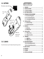
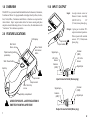
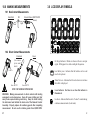
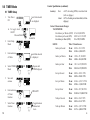
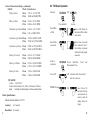
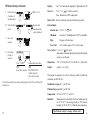
Servicing Europe: OMEGAnet ® Online Service www.omega.com Internet e-mail [email protected] Servicing North America: USA: ISO 9001 Certified Canada: One Omega Drive, Box 4047 Stamford CT 06907-0047 Tel: (203) 359-1660 e-mail: [email protected] FAX: (203) 359-7700 976 Bergar Laval (Quebec) H7L 5A1, Canada Tel: (514) 856-6928 FAX: (514) 856-6886 e-mail: [email protected] Benelux: Czech Republic: Frystatska 184, 733 01 Karviná, Czech Republic Tel: +420 (0)59 6311899 FAX: +420 (0)59 6311114 Toll Free: 0800-1-66342 e-mail: [email protected] France: 11, rue Jacques Cartier, 78280 Guyancourt, France Tel: +33 (0)1 61 37 2900 FAX: +33 (0)1 30 57 5427 Toll Free in France: 0800 466 342 e-mail: [email protected] Customer Service: 1-800-622-2378 / 1-800-622-BEST® Engineering Service: 1-800-872-9436 / 1-800-USA-WHEN® TELEX: 996404 EASYLINK: 62968934 CABLE: OMEGA Mexico: En Espan˜ol: (001) 203-359-7803 FAX: (001) 203-359-7807 NIST User’s Guide Germany/Austria: Daimlerstrasse 26, D-75392 Deckenpfronn, Germany Tel: +49 (0)7056 9398-0 FAX: +49 (0)7056 9398-29 Toll Free in Germany: 0800 639 7678 e-mail: [email protected] For immediate technical or application assistance: USA and Canada: Sales Service: 1-800-826-6342 / 1-800-TC-OMEGA® MADE IN Postbus 8034, 1180 LA Amstelveen, The Netherlands Tel: +31 (0)20 3472121 FAX: +31 (0)20 6434643 Toll Free in Benelux: 0800 0993344 e-mail: [email protected] United Kingdom: One Omega Drive, River Bend Technology Centre ISO 9002 Certified e-mail:[email protected] [email protected] Northbank, Irlam, Manchester M44 5BD United Kingdom Tel: +44 (0)161 777 6611 FAX: +44 (0)161 777 6622 Toll Free in United Kingdom: 0800-488-488 e-mail: [email protected] It is the policy of OMEGA to comply with all worldwide safety and EMC/EMI regulations that apply. OMEGA is constantly pursuing certification of its products to the European New Approach Directives. OMEGA will add the CE mark to every appropriate device upon certification. The information contained in this document is believed to be correct, but OMEGA Engineering, Inc. accepts no liability for any errors it contains, and reserves the right to alter specifications without notice. WARNING: These products are not designed for use in, and should not be used for, human applications. WARRANTY/DISCLAIMER OMEGA ENGINEERING, INC. warrants this unit to be free of defects in materials and workmanship for a period of 13 months from date of purchase. OMEGA’s WARRANTY adds an additional one (1) month grace period to the normal one (1) year product warranty to cover handling and shipping time. This ensures that OMEGA’s customers receive maximum coverage on each product. If the unit malfunctions, it must be returned to the factory for evaluation. OMEGA’s Customer Service Department will issue an Authorized Return (AR) number immediately upon phone or written request. Upon examination by OMEGA, if the unit is found to be defective, it will be repaired or replaced at no charge. OMEGA’s WARRANTY does not apply to defects resulting from any action of the purchaser, including but not limited to mishandling, improper interfacing, operation outside of design limits, improper repair, or unauthorized modification. This WARRANTY is VOID if the unit shows evidence of having been tampered with or shows evidence of having been damaged as a result of excessive corrosion; or current, heat, moisture or vibration; improper specification; misapplication; misuse or other operating conditions outside of OMEGA’s control. Components which wear are not warranted, including but not limited to contact points, fuses, and triacs. OMEGA is pleased to offer suggestions on the use of its various products. However, OMEGA neither assumes responsibility for any omissions or errors nor assumes liability for any damages that result from the use of its products in accordance with information provided by OMEGA, either verbal or written. OMEGA warrants only that the parts manufactured by it will be as specified and free of defects. OMEGA MAKES NO OTHER WARRANTIES OR REPRESENTATIONS OF ANY KIND WHATSOEVER, EXPRESS OR IMPLIED, EXCEPT THAT OF TITLE, AND ALL IMPLIED WARRANTIES INCLUDING ANY WARRANTY OF MERCHANTABILITY AND FITNESS FOR A PARTICULAR PURPOSE ARE HEREBY DISCLAIMED. LIMITATION OF LIABILITY: The remedies of purchaser set forth herein are exclusive, and the total liability of OMEGA with respect to this order, whether based on contract, warranty, negligence, indemnification, strict liability or otherwise, shall not exceed the purchase price of the component upon which liability is based. In no event shall OMEGA be liable for consequential, incidental or special damages. Shop online at omega.com e-mail: [email protected] For latest product manuals: omegamanual.info CONDITIONS: Equipment sold by OMEGA is not intended to be used, nor shall it be used: (1) as a “Basic Component” under 10 CFR 21 (NRC), used in or with any nuclear installation or activity; or (2) in medical applications or used on humans. Should any Product(s) be used in or with any nuclear installation or activity, medical application, used on humans, or misused in any way, OMEGA assumes no responsibility as set forth in our basic WARRANTY / DISCLAIMER language, and, additionally, purchaser will indemnify OMEGA and hold OMEGA harmless from any liability or damage whatsoever arising out of the use of the Product(s) in such a manner. RETURN REQUESTS / INQUIRIES Direct all warranty and repair requests/inquiries to the OMEGA Customer Service Department. BEFORE RETURNING ANY PRODUCT(S) TO OMEGA, PURCHASER MUST OBTAIN AN AUTHORIZED RETURN (AR) NUMBER FROM OMEGA’S CUSTOMER SERVICE DEPARTMENT (IN ORDER TO AVOID PROCESSING DELAYS). The assigned AR number should then be marked on the outside of the return package and on any correspondence. The purchaser is responsible for shipping charges, freight, insurance and proper packaging to prevent breakage in transit. PATENT NOTICE: U. S. Pat. No. 6,074,089; 5,465,838 / Canada 2,228,333; 2,116,055 / UK GB 2,321,712 / Holland 1008153 / Israel 123052 / France 2 762 908 / EPO 0614194. Other patents pending. FOR WARRANTY RETURNS, please have the following information available BEFORE contacting OMEGA: 1. Purchase Order number under which the product was PURCHASED, 2. Model and serial number of the product under warranty, and 3. Repair instructions and/or specific problems relative to the product. FOR NON-WARRANTY REPAIRS, consult OMEGA for current repair charges. Have the following information available BEFORE contacting OMEGA: 1. Purchase Order number to cover the COST of the repair, 2. Model and serial number of the product, and 3. Repair instructions and/or specific problems relative to the product. OMEGA’s policy is to make running changes, not model changes, whenever an improvement is possible. This affords our customers the latest in technology and engineering. OMEGA is a registered trademark of OMEGA ENGINEERING, INC. © Copyright 2004 OMEGA ENGINEERING, INC. All rights reserved. This document may not be copied, photocopied, reproduced, translated, or reduced to any electronic medium or machine-readable form, in whole or in part, without the prior written consent of OMEGA ENGINEERING, INC. M4151/0507 HHT13 Pocket Laser Tachometer with Remote Sensor Input SAFEGUARDS AND PRECAUTIONS LASER RADIATION AVOID DIRECT EYE EXPOSURE CLASS 2 LASER PRODUCT MAX OUTPUT POWER: 1mW EMITTED WAVELENGTH: 650nm CLASSIFIED TO IEC 60825-1:2001 WARNING - This product emits a visible beam of laser light. Avoid exposure to the laser radiation. The use of optical viewing aids (binoculars, for example) may increase the ocular hazard. CAUTION - The laser beam should not be intentionally aimed at people or animals. CAUTION - Use of controls or adjustments or performance of procedures other than those specified herein may result in hazardous radiation exposure. Read and follow all instructions in this manual carefully, and retain this manual for future reference. 14.0 OPTIONS / ACCESSORIES HHT-RT-5 Reflective Tape, 5 foot [1.5 m] roll, ½ inch [13 mm] wide HHT13-RCA Remote Contact Assembly with 10 cm wheel, concave and convex tips HHT13-CTE Concave/convex contact tips and 10 cm linear contact wheel HHT13-LCW 12 inch circumference wheel for use with HHT13RCA HHT20-ROS Remote Optical Sensor HHT-ROS-CABLE 25 foot extension cable for all sensors HHT13-CC10 Padded Nylon Carrying Case Do not use this instrument in any manner inconsistent with these operating instructions or under any conditions that exceed the environmental specifications stated. This instrument is not user serviceable. For technical assistance, contact the sales organization from which you purchased the product. In order to comply with EU Directive 2002/96/EC on Waste Electrical and Electronic Equipment (WEEE): This product may contain material which could be hazardous to human health and the environment. DO NOT DISPOSE of this product as unsorted municipal waste. This product needs to be RECYCLED in accordance with local regulations, contact your local authorities for more information. This product may be returnable to your distributor for recycling - contact the distributor for details. 24 12.0 BATTERIES TABLE OF CONTENTS When displayed, replace batteries. 1.0 2.0 3.0 4.0 5.0 Remove battery cover Install two 1.5V “AA” alkaline batteries 6.0 7.0 NOTE: Both batteries face the same direction. 13.0 CLEANING 8.0 9.0 10.0 To clean the instrument, wipe with a damp cloth using mild soapy solution. 11.0 12.0 13.0 14.0 23 OVERVIEW ............................................................................. 1 FEATURE LOCATIONS ............................................................ 1 LCD DISPLAY SYMBOLS ....................................................... 2 HHT13 SPECIFICATIONS ........................................................ 3 PREPARATION FOR MEASUREMENT .................................... 7 5.1 Non-Contact Preparation ............................................. 7 5.2 Direct Contact Preparation .......................................... 7 5.3 Connecting External Sensors ..................................... 8 TACHometer Mode ................................................................ 9 6.1 TACHometer Setup ....................................................... 9 6.2 TACHometer Operation .............................................. 11 RATE Mode ........................................................................... 12 7.1 RATE Setup ................................................................. 12 7.2 RATE Operation .......................................................... 14 TOTALizer Mode .................................................................. 15 8.1 TOTALizer Setup ......................................................... 15 8.2 TOTALizer Operation .................................................. 18 TIMER Mode ......................................................................... 19 9.1 TIMER Setup ................................................................ 19 9.2 TIMER Operation ......................................................... 20 MAKING MEASUREMENTS .................................................. 21 10.1 Non-Contact Measurements ..................................... 21 10.2 Direct Contact Measurements .................................. 21 INPUT / OUTPUT .................................................................. 22 BATTERIES ........................................................................... 23 CLEANING ............................................................................ 23 OPTIONS /ACCESSORIES ................................................... 24 1.0 OVERVIEW 11.0 INPUT / OUTPUT The HHT13 is a precision hand-held multifunction Tachometer, Ratemeter, Totalizer and Timer. It is programmable to display directly in Revs, Inches, Feet, Yards, Miles, Centimeters and Meters or function as a stopwatch or interval timer. Input / output sockets allow for remote sensing and pulse output to external indicating devices. For ease of use, the instrument can be “Locked-on” for continuous operation. Input: Output: 1 pulse per revolution TTL output on internal operation. Pulse repeater with external sensors. 1/8” (3.5mm) mono Input socket (S) phone plug. 2.0 FEATURE LOCATIONS LCD display Min / Scroll Down arrow Accepts remote sensor or Remote Contact Assembly (HHT13-RCA). 1/8” (3.5mm) stereo phone plug. Output socket (T ) Menu / Select and Lock-on button Tripod mounting bushing (underside) Signal Input +3V Out to Sensor Start / Reset button Common (GND) Belt clip Input socket Common (GND) +3V Out to Sensor Signal Input Input Connector Detail (Stereo plug) Output socket Max / Scroll Up arrow Battery compartment Signal Input Common (GND) Common (GND) Signal Input AVOID EXPOSURE - LASER RADIATION IS EMITTED FROM THIS APERTURE Output Connector Detail (Mono plug) 1 22 10.0 MAKING MEASUREMENTS 3.0 LCD DISPLAY SYMBOLS 10.1 Non-Contact Measurements Hand-held OR Light Laser External Sensor (HHT20-ROS shown) 10.2 Direct Contact Measurements Rotational Linear (Use concave tip for small shafts) On Target Indicator. Blinks on whenever there is an input signal. Will appear to be solid on at higher frequencies. to RCA from HHT13 Low Battery icon. Indicates that the batteries are low and need to be replaced. from HHT13 ONLY USE MODERATE PRESSURE WARNING: Making measurements in direct contact with rotating equipment can be dangerous. Keep all loose clothing and hair away from exposed moving machinery. Keep the hand holding the instrument well behind the back end of the Remote Contact Assembly. Properly replace all machinery guards after completing measurement. Do not use for rotation greater than 20,000 RPM. 21 Times Ten icon. Indicates that the value shown is ten times that which is displayed. Laser Indicator. Red laser is on when this indicator is illuminated. Lock icon. Indicates that the unit is “Locked” on and making continuous measurements (Lock mode). 2 4.0 HHT13 SPECIFICATIONS 8. Save and advance 9. Exit Setup – Ready to measure Laser Specifications: Classification: Class 2 (per IEC 60825-1 Ed 1.2 2001-8) Complies with FDA performance standards for laser products except for deviations pursuant to Laser Notice No. 50, dated July 26, 2001. Maximum Laser Output: Pulse Duration: Laser Wavelength: Beam Divergence: Beam Diameter: Laser Diode Life: 1mW Continuous 650 nm < 1.5 mrad 4 x 7 mm typical at 2 meters 8,000 operating hours MTBF (1 year warranty) Unit will remember these settings (including lock on/off) even if turned off and back on. 9.2 TIMER Operation Measure: Manual Non-Contact Specifications: Ranges: RPM RPS RPH 5 – 200,000 0.084 – 3,333.3 300-999,990 Auto Resolution: Fixed: 1 (10 above 99,999) Auto-ranging: 0.001 to 1.0 (10 above 99,999) Accuracy: ±0.01% of reading or resolution limit Range: Contact Tips: 0.5 to 20,000 RPM 10 cm / 12-inch Wheel: 0.5 to 12,000 RPM Resolution: Fixed: Auto-ranging: 3 1 (10 above 99,999) 0.001 to 1.0 (10 above 99,999) Each press toggles Start and Stop OR Start and Stop triggered by Remote Optical Sensor (HHT20-ROS) Reset With Timer stopped Resets time to 00:00.0 Lap With Timer running Stops at elapsed time to date. To continue, press again. Power Off OR Automatic after 90 seconds if unit not Locked on Operating Range: up to 25 feet (7.62 m) or up to 70 degrees off perpendicular to reflective tape target Contact Specifications using optional Remote Contact Assembly: DONE, then Units selected 20 9.0 TIMER Mode Contact Specifications (continued): Accuracy: 9.1 TIMER Setup 1. Turn Power ON Last Units selected are displayed 1a. To toggle Lock On/Off Press and Hold 2. 3. Enter selection of Mode 4. Select TIMER Mode 5. Save and advance 6. Enter selection of Timer function 7. 19 Locked On Enter Setup Mode Select Timer function Revs: Linear: ±0.05% of reading (RPM) or resolution limit (with no slippage) ±0.5% of reading or resolution limit (with no slippage) Contact Measurements Ranges: TACHOMETER: Revolutions per Minute (RPM) 0.5 to 20,000 RPM Revolutions per Second (RPS) 0.0833 to 333.33 RPS Revolution per Hour (RPH) 30 to 999,990 RPH RATES: Inches per Second Last Mode selected is displayed OR Repeat until TIMER displayed MAN or AUTO OR Toggles between Manual and Auto Wheel Circumference: 10 cm: 0.033 to 1312.3 IPS 12 in: 0.100 to 2,400.0 IPS Inches per Minute 10 cm: 12 in: 1.969 to 78,740 IPM 6.000 to 144,000 IPM Inches per Hour 10 cm: 12 in: 118.11 to 999,990 IPH 360.00 to 999,990 IPH Feet per Second 10 cm: 12 in: 0.003 to 109.36 FT/S 0.009 to 200.00 FT/S Feet per Minute 10 cm: 12 in: 0.164 to 6,561.7 FT/M 0.500 to 12,000 FT/M Feet per Hour 10 cm: 12 in: 9.843 to 393,700 FT/H 30.000 to 720,000 FT/H Yards per Second 10 cm: 12 in: 0.001 to 36.453 YPS 0.003 to 66.667 YPS Yards per Minute 10 cm: 12 in: 0.055 to 2,187.2 YPM 0.167 to 4,000.0 YPM 4 Contact Measurements Ranges (continued): RATES: Wheel Circumference: Yards per Hour 10cm: 3.281 to 131,233 YPH 12 in: 10.000 to 240,000 YPH Miles per Hour 10 cm: 12 in: 0.084 to 3,333.3 CM/S 0.21 to 3,048.0 CM/S Centimeters per Minute 10 cm: 12 in: 5.000 to 200,000 CM/M 15.240 to 365,760 CM/M Centimeters per Hour 10 cm: 12 in: 300.00 to 999,990 CM/H 914.40 to 999,990 CM/H Meters per Second 10 cm: 12 in: 0.001 to 33.333 M/SEC 0.003 to 60.960 M/SEC Meters per Minute 10 cm: 12 in: 0.050 to 2,000.0 M/MIN 0.153 to 3,657.6 M/MIN Meters per Hour 10 cm: 12 in: 3.000 to 120,000 M/H 9.144 to 219,460 M/H TOTALIZER: Counts: 0 to 999,999 Scale Totals in Inches, Feet, Yards, Centimeters or Meters Input: Internal or External optics or linear contact wheel Minutes:Seconds.Tenths to 99:59.9 Accuracy: ±0.2 second Measure 0.002 to 74.564 MPH 0.006 to 136.36 MPH Centimeters per Second 10 cm: 12 in: Timer Specifications: 8.2 TOTALizer Operation OR Press and hold Lock on Recall Max or Min Max or Min Speed (in last selected Tach or Rate mode units) Recall Time in seconds Shows time in seconds from when the Start / Reset button is pressed until the last input signal measured. If unit is Locked on: Resets Max/Min, Measurement Time Power Off OR Automatic after 90 seconds if unit not Locked on NOTE: Pressing OR Total and once before 90 seconds will keep measurements in memory and the display turned on longer. Resolution: 0.1 second 5 18 TOTALizer Setup (continued): 9. Enter selection of number of decimal places 10. Select decimal places NONE, 1, 2 or 3 Display: 5 x 0.5” (12.7mm) numeric digits plus 5 Alpha-numeric LCD Batteries: 2 “AA” 1.5 V (DC) alkaline included (Note: Batteries are NOT rechargeable.) Battery Life: 30 hours continuous typical with batteries provided OR Repeat until desired decimal places displayed 11. Save and advance External Input: Absolute max: -0.3 V to 5 V (DC) Minimum: low below 1.2 V and high above 2 V (TTL compatible) Edge: Triggers on Positive edge Power Out: 3.0 V nominal, approx. 2.8 V @ 20 mA max Pulse Output: 0 V to 3.3 V (DC) pulse Same shape as External Input signal or high when internal optics sees a reflection 12. Exit Setup – Ready to measure Units = COUNT: DONE, then Units selected Rotational/Linear Units: DONE, USE CONTACT TIP or [wheel selected], then Units selected Unit will remember these settings (including lock on/off) even if turned off and back on. Dimensions: 6.92” (17.58 cm) H x 2.4” (6.10 cm) W x 1.6” (4.06 cm) D Weight: Approx. 7 oz. (210 g) This product is designed to be safe for indoor use under the following conditions (per IEC61010-1). Installation Category II per IEC 664 Pollution Degree Level II per IEC 664 Temperature: 40 °F to 105 °F (5 °C to 40 °C) Humidity: 17 Maximum relative humidity of 80% for temperatures up to 88 °F (31 °C) decreasing linearly to 50% relative humidity at 100 °F (40 °C). Humidity non-condensing. Specifications subject to change without notice. 6 5.0 PREPARATION FOR MEASUREMENT 6. 5.1 Non-Contact Preparation 2. Apply 1/2” square T-5 Reflective tape For Small Shafts: Different options displayed for Internal or External operation. Internal or External ROS: External RCA: COUNT Rotational: REV Only Linear: INCH, FEET, YARDS, CM, METER For Internal operation (Red laser) or External operation using optional Remote Optical Sensor (ROS-Red LED). 1. Clean Shaft Enter selection of Units 7. Select Units 8. Save and advance As small as 1/8” wide on side or radius edge OR Repeat until desired Units displayed OR COUNT or REV Only for Linear Units: 8a. Enter selection of Wheel 5.2 Direct Contact Preparation For External operation ONLY using optional Remote Contact Assembly (HHT13-RCA). 8b. Select Wheel Select and install contact option: 8c. Save and Advance 1. Contact Tip (Convex tip shown. Use Concave tip for small shafts.) Linear Units Last Wheel selected is displayed OR Toggles between 10CM and 12IN Align flats 7 16 8.0 TOTALizer Mode OR 2. 10 cm Wheel 3. 12 inch Wheel 8.1 TOTALizer Setup 1. Turn Power ON Different messages displayed for Internal or External operation. Internal or External ROS: Last Units selected External RCA: EXTRN, then scrolling message, then last Units selected Enter Setup Mode 3. Enter selection of Mode Tighten screw securely into flat on shaft. 5.3 Connecting External Sensors 1a. To toggle Lock On/ Off Press and Hold 2. Install with pin in shaft fully seated in slot. Tighten screw. Locked On Last Mode selected is displayed S Plug sensor into Input socket In 4. Select TOTAL Mode 5. Save and advance OR Repeat until TOTAL displayed. Remote Optical Sensor (HHT20-ROS) Remote Contact Assembly (HHT13-RCA) (shown with optional 12 inch wheel) 15 8 6.0 TACHometer Mode 11. Save and advance 6.1 TACHometer Setup 1. Turn Power ON Last Units selected are displayed 1a. To toggle Lock On/ Off Press and Hold 2. 3. 4. 5. 6. 9 Locked On Enter Setup Mode Unit will remember these settings (including lock on/off) even if turned off and back on. Measure Last Mode selected is displayed OR OR Press and hold Lock on Recall Max Max Speed Recall Min Min Speed Repeat until TACH displayed Save and advance Enter selection of Units DONE, USE CONTACT TIP or [wheel selected], then Units selected 7.2 RATE Operation Enter selection of Mode Select TACH Mode 12. Exit Setup – Ready to measure RPS, RPM or RPH If unit Locked on: Resets Max/Min Power Off OR Automatic after 90 seconds if unit not Locked on 14 RATE Setup (continued): 6. 7. 8. Enter selection of Units Select Units Linear: IPS, IPM, IPH, FT/S, FT/M, FT/H, YPS, YPM, YPH, MPH, CM/S, CM/M, CM/H, M/SEC, M/MIN, M/H OR Repeat until desired Units displayed OR Rotational Units Linear Units Only for Linear Units: 8a. Enter selection of Wheel Last Wheel selected is displayed OR Toggles between 10CM and 12IN 8c. Save and Advance 9. Enter selection of number of decimal places 10. Select decimal places 13 Select Units 8. Save and advance 9. Enter selection of number of decimal places OR Rotational: C RPS, C RPM or C RPH Save and advance 8b. Select Wheel 7. NONE, 1, 2 or 3 OR 10. Select decimal places Repeat until desired Units displayed NONE, 1, 2 or 3 OR Repeat until desired decimal places displayed 11. Save and advance 12. Exit Setup – Ready to measure DONE, then Units selected Unit will remember these settings (including lock on/off) even if turned off and back on. Repeat until desired decimal places displayed 10 7.0 RATE Mode 6.2 TACHometer Operation Press and hold 11 NOTE: OR Measure External Remote Contact Assembly (HHT13-RCA) must be inserted into input socket. 7.1 RATE Setup Lock on Recall Max Max Speed Recall Min Min Speed 1. Turn Power ON 1a. To toggle Lock On/Off Press and Hold If unit Locked on: Resets Max/Min 2. Enter Setup Mode Power OFF OR 3. Enter selection of Mode 4. Select RATE Mode 5. Save and advance Automatic after 90 seconds if unit not Locked on EXTRN, then scrolling message, then last Units selected Locked On Last Mode selected is displayed OR Toggles between RATE and TOTAL. Select RATE. 12