1
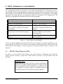
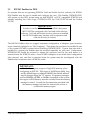
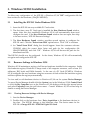
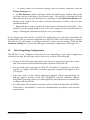
(1*,1((5,1* ,1& IOP-241 24 Channel Digital Input/Output Type II PCMCIA Card Users Manual INTERFACE CARDS FOR PERSONAL COMPUTERS OMEGA ENGINEERING, INC. One Omega Drive P.O. Box 4047 Stamford, CT 06907-4047 Tel: (203) 359-1660 Fax: (203) 359-7700 Toll free: 1-800-826-6342 E-mail: [email protected] http://www.dasieee.com IOP-241 Users Manual 1 WARRANTY/DISCLAIMER OMEGA ENGINEERING, INC., warrants this unit to be free of defects in materials and workmanship for a period of 13 months from the date of purchase. OMEGA warranty adds an additional one (1) month grace period to the normal one (1) year product warranty to cover shipping and handling time. This ensures that OMEGA’s customers receive maximum coverage on each product. If the unit should malfunction, it must be returned to the factory for evaluation. OMEGA’s Customer Service Department will issue an Authorized Return (AR) number immediately upon phone or written request. Upon examination by OMEGA, if the unit is found to be defective it will be repaired or replaced at no charge. OMEGA’s warranty does not apply to defects resulting from any action of the purchaser, including but not limited to mishandling, improper interfacing, operation outside design limits, improper repair or unauthorized modification. This WARRANTY is VOID if the unit shows evidence of having been tampered with or shows evidence of being damaged as a result of excessive corrosion; or current, heat, moisture or vibration; improper specification; misapplication; misuse or other operating conditions outside of OMEGA’s control. Components which wear are not warranted, including but not limited to contact points, fuses and triacs. OMEGA is pleased to offer suggestions on the use of its various products. However, OMEGA neither assumes responsibility for any omissions or errors nor assumes liability for any damages that result from the use of its products in accordance with information provided from OMEGA, either verbal or written. OMEGA warrants only that the parts manufactured by it will be as specified and free of defects. OMEGA MAKES NO OTHER WARRANTIES OR REPRESENTATIONS OF ANY KIND WHATSOEVER, EXPRESSED OR IMPLIED, EXCEPT THAT OF TITLE, AND ALL IMPLIED WARRANTIES INCLUDING ANY WARRANTY OF MERCHANTABILITY AND FITNESS FOR A PARTICULAR PURPOSE ARE HEREBY DISCLAIMED. LIMITATION OF LIABILITY: The remedies of purchaser set forth herein are exclusive and the total liability of OMEGA with respect to this order, whether based on contract, warranty, negligence, indemnification, strict liability or otherwise, shall not exceed the purchase price of the component upon which liability is based. In no event shall OMEGA be liable for consequential, incidental or special damages. CONDITIONS: Equipment sold by OMEGA is not intended to be used, nor shall it be used: (1) as a “Basic Component” under 10 CFR 21 (NRC), used in or with any nuclear installation or activity, medical application or used on humans. Should any Product(s) be used in or with any nuclear installation or activity, medical application, used on humans or misused in any way, OMEGA assumes no responsibility as set forth in our basic WARRANTY/DISCLAIMER language, and additionally, purchaser will indemnify OMEGA and hold OMEGA harmless from any liability or damage whatsoever arising out of the use of the Product(s) in such a manner. RETURN REQUESTS/INQUIRIES Direct all warranty and repair requests/inquiries to the OMEGA Customer Service Department. BEFORE RETURNING ANY PRODUCT(S) TO OMEGA, PURCHASER MUST OBTAIN AN AUTHORIZED RETURN (AR) NUMBER FROM OMEGA’S CUSTOMER SERVICE DEPARTMENT (IN ORDER TO AVOID PROCESSING DELAYS). THE ASSIGNED NUMBER SHOULD THEN BE MARKED ON THE OUTSIDE OF THE RETURN PACKAGE AND ON ANY CORRESPONDENCE. THE PURCHASER IS RESPONSIBLE FOR SHIPPING CHARGES, FREIGHT, INSURANCE AND PROPER PACKAGING TO PREVENT BREAKAGE IN TRANSIT. FOR WARRANTY RETURNS, please have the following information available BEFORE contacting OMEGA: (1) P.O. Number under which the product was purchased, (2) Model and serial number of the product under warranty, and (3) Repair instructions and/or specific problems relative to the product. FOR NON-WARRANTY REPAIRS, consult OMEGA for current repair charges. Have the following information available BEFORE contacting OMEGA: (1) P.O. Number to cover the cost of the repair, (2) Model and serial number of the product, and (3) Repair instructions relative to the product. OMEGA’s policy is to make running changes, not model changes, whenever an improvement is possible. This affords our customers the latest in technology and engineering. OMEGA is a registered trademark of OMEGA ENGINEERING, INC. © Copyright 1999 OMEGA ENGINEERING, INC. All rights reserved. This document may not be copied, photocopied, reproduced, translated or reduced to any electronic medium or machine readable form, in whole or in part, without prior written consent of OMEGA ENGINEERING, INC. IOP-241 Users Manual 2 Declaration of Conformity Manufacturer's Name: Omega Engineering, Inc. Manufacturer’s Address: One Omega Drive Stamford, CT 06907-0047 Application of Council Directive: 89/336/EEC Standards to which Conformity is Declared: * EN50081-2 (EN55022) * EN50082-1 (IEC 801-2, IEC 801-3, & IEC 801-4) Type of Equipment: Information Technology Equipment Equipment Class: Commercial, Residential and Light Industrial Product Name: PCMCIA Card Model Number : IOP-241 IOP-241 Users Manual 3 OMEGAnet On-line Service: http://www.omega.com Internet e-mail: [email protected] Servicing North America: USA: ISO 9001 Certified Canada: One Omega Drive, Box 4047 Stamford, CT 06907-0047 Tel: (203) 359-1660 E-mail: [email protected] 976 Bergar Laval (Quebec) H7L 5A1 Tel: (514) 856-6928 E-mail: [email protected] FAX: (203) 359-7700 FAX: (514) 856-6886 For immediate technical or application assistance: USA and Canada: Sales Service: 1-800-826-6342 / 1-800-TC-OMEGA SM Customer Service: 1-800-622-2378/ 1-800-622-BEST SM Engineering Service: 1-800-872-9436 / 1-800-USA-WHEN SM TELEX: 996404 EASYLINK: 62968934 CABLE: OMEGA Mexico and Latin America: Tel: (001) 800-826-6342 En Espanol: (001) 203-359-7803 E-mail: [email protected] FAX: (001) 203-359-7807 Servicing Europe: Benelux: Postbus 8034, 1180 LA Amstelveen, The Netherlands Tel: (31) 20 6418405 Toll Free in Benelux: 0800 0993344 E-mail: [email protected] Czech Republic: ul.Rude armady 1868, 733 01 Karvina-Hraniee Tel: 42 (69) 6311899 Toll Free: 0800-1-66342 FAX: 42 (69) 6311114 E-mail: [email protected] France: 9, rue Denis Papin, 78190 Trappes Tel: (33) 130-621-400 Toll Free in France: 0800-4-06342 E-mail: [email protected] Germany/Austria: Daimlerstrasse 26, D-75392 Deckenpfronn, Germany Tel: 49 (07056) 3017 Toll Free in Germany: 0130 11 21 66 E-mail: [email protected] IOP-241 Users Manual 4 United Kingdom: ISO 9002 Certified One Omega Drive, River Bend Technology Drive Northbank, Irlam, Manchester M44 5EX, England Tel: 44 (161) 777-6611 FAX: 44 (161) 777-6622 Toll Free in England: 0800-488-488 E-mail: [email protected] It is the policy of OMEGA to comply with all worldwide safety and EMC/EMI regulations that apply. OMEGA is constantly pursuing certification of it’s products to the European New Approach Directives. OMEGA will add the CE mark to every appropriate device upon certification. The information contained in this document is believed to be correct but OMEGA Engineering, Inc. accepts no liability for any errors it contains, and reserves the right to alter specifications without notice. WARNING: These products are not designed for use in, and should not be used for, patient connected applications. IOP-241 Users Manual 5 Table of Contents 1. Introduction ......................................................... 9 1.1 IOP-241 Features . . . . . . . . . . . . . . . . . . . . . . . . . . . . . . . . . . . . . . . . . . . . . . . . . . 9 1.2 System Configuration . . . . . . . . . . . . . . . . . . . . . . . . . . . . . . . . . . . . . . . . . . . . . . 9 2. DOS / Windows 3.x Installation ............................... 2.1 IOP-241 Client Driver for DOS . . . . . . . . . . . . . . . . . . . . . . . . . . . . . . . . . . . . 2.1.1 Client Driver Installation . . . . . . . . . . . . . . . . . . . . . . . . . . . . . . . . . . . . . . . . . . . 2.1.2 Command Line Options . . . . . . . . . . . . . . . . . . . . . . . . . . . . . . . . . . . . . . . . . . . . 2.1.3 Common Problems . . . . . . . . . . . . . . . . . . . . . . . . . . . . . . . . . . . . . . . . . . . . . . . . 2.2 IOP-241 Enabler for DOS . . . . . . . . . . . . . . . . . . . . . . . . . . . . . . . . . . . . . . . . . 2.2.1 Enabler Installation . . . . . . . . . . . . . . . . . . . . . . . . . . . . . . . . . . . . . . . . . . . . . . . . 2.2.2 Command Line Options . . . . . . . . . . . . . . . . . . . . . . . . . . . . . . . . . . . . . . . . . . . . 2.2.3 Common Problems . . . . . . . . . . . . . . . . . . . . . . . . . . . . . . . . . . . . . . . . . . . . . . . . 2.3 After Completing Configuration . . . . . . . . . . . . . . . . . . . . . . . . . . . . . . . . . . 3. Windows 95/98® Installation ................................... 3.1 Installing the IOP-241 Under Windows 95/98 . . . . . . . . . . . . . . . . . . . . . 3.2 Resource Settings in Windows 95/98 . . . . . . . . . . . . . . . . . . . . . . . . . . . . . . 3.2.1 Viewing Resource Settings with Device Manager . . . . . . . . . . . . . . . . . . . . . . . 3.3 Changing Resource Settings with Device Manager . . . . . . . . . . . . . . . . 3.4 After Completing Configuration . . . . . . . . . . . . . . . . . . . . . . . . . . . . . . . . . . 4. Theory of Operation .............................................. 4.1 I/O Port Description . . . . . . . . . . . . . . . . . . . . . . . . . . . . . . . . . . . . . . . . . . . . . 4.2 Port C Interrupt Description . . . . . . . . . . . . . . . . . . . . . . . . . . . . . . . . . . . . . . 4.3 External Interrupt Description . . . . . . . . . . . . . . . . . . . . . . . . . . . . . . . . . . . . 5. Register Descriptions ............................................ 5.1 Data Port A Control Register (Base + 0) . . . . . . . . . . . . . . . . . . . . . . . . . . . 5.2 Data Port B Control Register (Base + 1) . . . . . . . . . . . . . . . . . . . . . . . . . . . . 5.3 Data Port C Control Register (Base + 2) . . . . . . . . . . . . . . . . . . . . . . . . . . . . 5.4 Port C Interrupt Enable Register (Base + 5) . . . . . . . . . . . . . . . . . . . . . . . . 5.5 Interrupt Mode Control Register (Base + 6) . . . . . . . . . . . . . . . . . . . . . . . . 5.6 Interrupt Status Register (Read Only) (Base + 7) . . . . . . . . . . . . . . . . . . . 5.7 Interrupt Acknowledge Register (Write Only) (Base + 7) . . . . . . . . . . . 5.8 Summary of Interrupt Source Options . . . . . . . . . . . . . . . . . . . . . . . . . . . . . 5.9 Summary of Input/Output Options . . . . . . . . . . . . . . . . . . . . . . . . . . . . . . . 5.10 Programming Example . . . . . . . . . . . . . . . . . . . . . . . . . . . . . . . . . . . . . . . . . . IOP-241 Users Manual 10 10 11 12 14 15 16 17 18 19 20 20 20 20 21 22 23 23 24 24 25 25 26 26 27 28 28 29 29 30 31 6 6. External Connections . . . . . . . . . . . . . . . . . . . . . . . . . . . . . . . . . . . . . . . . . . . . . 32 7. Optional Accessories . . . . . . . . . . . . . . . . . . . . . . . . . . . . . . . . . . . . . . . . . . . . . 33 7.1 CP-1037 Cable Assembly . . . . . . . . . . . . . . . . . . . . . . . . . . . . . . . . . . . . . . . . . 33 7.2 UIO-37 Screw Terminal Block . . . . . . . . . . . . . . . . . . . . . . . . . . . . . . . . . . . . 34 8. Specifications IOP-241 Users Manual . . . . . . . . . . . . . . . . . . . . . . . . . . . . . . . . . . . . . . . . . . . . . . . . . . . . . . 35 7 List of Figures and Tables Figure 1-1. Figure 3-1. Figure 6-1. Figure 7-1. Figure 7-2. Table 1-1. Table 5-1. Table 5-2. Table 5-3. Table 5-4. Table 5-5. Table 5-6. Table 5-7. Table 5-8. IOP-241 System Configuration . . . . . . . . . . . . . . . . . . . . . . . . . . . . . . . . . . . . . . . . . 9 Windows 95/98 Resource Settings . . . . . . . . . . . . . . . . . . . . . . . . . . . . . . . . . . . . . 21 IOP-241 33-Pin Connector . . . . . . . . . . . . . . . . . . . . . . . . . . . . . . . . . . . . . . . . . . . . 32 CP-1037 D37 Pin Assignments . . . . . . . . . . . . . . . . . . . . . . . . . . . . . . . . . . . . . . . . . 33 UIO-37 Screw Terminal Block . . . . . . . . . . . . . . . . . . . . . . . . . . . . . . . . . . . . . . . . . 34 Client Driver versus Enabler . . . . . . . . . . . . . . . . . . . . . . . . . . . . . . . . . . . . . . . . . 10 IOP-241 Program Registers . . . . . . . . . . . . . . . . . . . . . . . . . . . . . . . . . . . . . . . . . . . 25 Data Port A Control Register . . . . . . . . . . . . . . . . . . . . . . . . . . . . . . . . . . . . . . . . . . 25 Data Port B Control Register . . . . . . . . . . . . . . . . . . . . . . . . . . . . . . . . . . . . . . . . . . 26 Data Port C Control Register . . . . . . . . . . . . . . . . . . . . . . . . . . . . . . . . . . . . . . . . . . 26 Port C Interrupt Control Register . . . . . . . . . . . . . . . . . . . . . . . . . . . . . . . . . . . . . . 27 Interrupt Mode Control Register . . . . . . . . . . . . . . . . . . . . . . . . . . . . . . . . . . . . . . . 28 Interrupt Status Register (Read Only) . . . . . . . . . . . . . . . . . . . . . . . . . . . . . . . . . . 28 Interrupt Status Register (Write Only) . . . . . . . . . . . . . . . . . . . . . . . . . . . . . . . . . . 29 IOP-241 Users Manual 8 1. Introduction The IOP-241 is a 24 channel digital input/output card for systems equipped with PCMCIA Type II and/or Type III expansion sockets. 1.1 IOP-241 Features 1.2 PC Card Standard Specification 2.10 Compliant 24 TTL compatible digital I/O channels (8 channels can be used as interrupt sources) Channels individually programmable as either input or output Active high sensitive, active low sensitive, low-to-high transistion or high-to-low transition interrupt modes (external interrupt available) System Configuration The figure below illustrates a complete IOP-241 system. For users that do not wish to interface to the IOP-241 0.8mm I/O connector, an optional adapter cable (CP-1037) is available to convert this connector into an industry standard D-37 connector. For applications requiring discrete wiring hook-ups, an optional screw terminal block (UIO-37) is available to convert the D-37 connector into 37 single screw terminal blocks. These optional accessories are described in detail in Chapter 7. D37 IOP-241 UIO-37 Hirose-32 CP-IO37 Figure 1-1. IOP-241 System Configuration IOP-241 Users Manual 9 2. DOS / Windows 3.x Installation Two configuration software programs are provided with the IOP-241: a Client Driver and a card Enabler. Both of these programs are executed from DOS (before entering Windows) and allow operation of the IOP-241 in both the DOS and Windows 3.x environments. For optimal operation, the Client Driver is the preferred method of installation and configuration. The table below highlights the differences between these programs. Client Driver (recommended) Enabler File name: IOP241CL.SYS File name: IOP241EN.EXE File type: DOS device driver File type: Interfaces to PCMCIA Card and Socket Services software (PCMCIA host adapter independent) Interfaces directly to Intel 82365SL and other PCIC compatible PCMCIA host adapters Allows automatic configuration of IOP-241 adapters upon insertion (Hot Swapping) Does not support automatic configuration of IOP-241 adapters upon insertion (Hot Swapping) Requires PCMCIA Card and Socket Services software Does not require PCMCIA Card and Socket Services software DOS executable Table 1-1. Client Driver versus Enabler If you are unsure whether Card and Socket Services software is currently installed on your system, install the IOP-241 Client Driver as discussed in following section. When loaded, the Client Driver will display an error message if Card and Socket Services software is not detected. 2.1 IOP-241 Client Driver for DOS In order to use the IOP-241 Client Driver, the system must be configured with Card and Socket Services software. (Card and Socket Services software is not provided with the IOP-241). IMPORTANT: Some versions of Card and Socket Services dated before 1993 do not support general purpose I/O cards. If after careful installation of the Client Driver, the IOP-241 does not configure or operate properly, an updated version of Card and Socket Services software may be required. IOP-241 Users Manual 10 2.1.1 Client Driver Installation The following procedure is used to install the IOP-241 Client Driver: 1. Copy the file IOP241CL.SYS from the customer software CD-ROM directory PCMCIA\DOS\CLIENTS onto the root directory of the system hard drive. 2. Using an ASCII text editor, open the system CONFIG.SYS file located in the root directory of the boot drive. 3. Locate the line(s) in the CONFIG.SYS file where the Card and Socket Services software is installed. 4. AFTER the line(s) installing the Card and Socket Services software, add the following to the CONFIG.SYS file: DEVICE = drive:\path\IOP241CL.SYS(options), where options are the IOP-241 Client Driver command line options discussed on the following pages. (Path is only required if the user places the Client Driver executable file in a directory other than the root directory). 5. Save the CONFIG.SYS file and exit the text editor. 6. Insert the IOP-241 into one of the system PCMCIA slots. NOTE: Since the IOP-241 Client Driver supports "Hot Swapping", it is not necessary to have the IOP-241 installed when booting the system. However, by inserting the card before booting, the Client Driver will report the card configuration during the boot process thereby verifying changes made to the CONFIG.SYS file. 7. Reboot the system and note the message displayed when the IOP-241 Client Driver is loaded. If the Client Driver reports an "invalid command line option", correct the entry in the CONFIG.SYS file and reboot the system again. If the Client Driver reports "Card and Socket Services not found", then Card and Socket Services software must be installed on the system or the IOP-241 Enabler program must be used to configure the card. If the Client Driver reports the desired card configuration, the installation process is complete and the IOP-241 may be removed and/or inserted from the system as desired. On each insertion into the PCMCIA socket, the IOP-241 will be automatically reconfigured according to the command line options. IOP-241 Users Manual 11 2.1.2 Command Line Options The Client Driver accepts up to eight command line arguments from the user to determine the configuration of the IOP-241. If any arguments are provided, the Client Driver will attempt to configure the IOP-241 with the options specified in the order they are entered on the command line. Each argument must be enclosed in parenthesis and must be separated from other arguments by a space on the command line. Within each argument, any or all of the following parameters may be specified using a comma (no spaces) to separate each parameter: b address Specifies the base I/O address of the IOP-241 in hexadecimal. “Address” must reside on an even 8-byte boundary (I/O base address must end in '0' or '8'). The valid range for the IOP-241’s base address is 100H to 3F8H. If this option is omitted, a base address is assigned by Card and Socket Services. i irq Specifies the interrupt level (IRQ) of the IOP-241 in decimal. “Irq” must be one of the following values: 3, 4, 5, 7, 9, 10, 11, 12, 14, 15 or 0 if no IRQ is desired. If this option is omitted, an interrupt level will be assigned by Card and Socket Services. s socket Specifies which PCMCIA socket the IOP-241 must be inserted into for this configuration argument to be used. “Socket” must be in the range of 0 - 15. If this option is omitted, the configuration argument will apply to cards inserted into any socket. 2.1.2.1 Example 1 DEVICE = C:\IOP241CL.SYS No command line arguments are specified. The Client Driver will configure an IOP-241 inserted into any socket with a base address and IRQ assigned by Card and Socket Services. 2.1.2.2 Example 2 DEVICE = C:\IOP241CL.SYS (b330) A single command line argument is provided. The Client Driver will attempt to configure an IOP-241 inserted into any socket at address 330H and an IRQ assigned by Card and Socket Services. If address 330H is unavailable, the IOP-241 will not be configured. 2.1.2.3 Example 3 DEVICE = C:\IOP241CL.SYS (s0,b300,i5) A single command line argument is provided. The Client Driver will attempt to configure an IOP-241 inserted into socket 0 with a base address of 300H and IRQ 5. If address 300H or IRQ 5 are unavailable, the IOP-241 will not be configured. In addition, if an IOP-241 is inserted into any other socket, it will not be configured. IOP-241 Users Manual 12 2.1.2.4 Example 4 DEVICE = C:\IOP241CL.SYS (i11,b300) A single command line argument is provided. Because the parameter order is not significant, the Client Driver will attempt to configure an IOP-241 inserted into any socket with a base address of 300H and IRQ 11. If address 300H or IRQ 11 are unavailable, the IOP-241 will not be configured. 2.1.2.5 Example 5 DEVICE = C:\IOP241CL.SYS (b300,i5) (i10) ( ) Three command line arguments are provided. The Client Driver will first attempt to configure an IOP-241 inserted into any socket with a base address of 300H and IRQ5. If address 300H or IRQ 5 are unavailable, the Client Driver will proceed to the second command line argument and attempt to configure the card with a base address assigned by Card and Socket Services and IRQ 10. If IRQ 10 is also unavailable, the Client Driver will proceed to the third command line argument and attempt to configure the IOP-241 with a base address and an IRQ assigned by Card and Socket Services. 2.1.2.6 Example 6 DEVICE = C:\IOP241CL.SYS (b300,i5) ( ) (i10) In example 6, the three command line arguments of example 5 have been rearranged. The Client Driver will first attempt to configure an IOP-241 inserted into any socket with a base address of 300H and IRQ 5. If address 300H or IRQ 5 are unavailable, the Client Driver will proceed to the second command line argument and attempt to configure the card with a base address and IRQ assigned by Card and Socket Services. Since the second command line argument includes all available address and IRQ resources, the third command line argument will never be reached by the Client Driver. The user must ensure the command line arguments are placed in a logical order. 2.1.2.7 Example 7 DEVICE = C:\IOP241CL.SYS (s0,b300,i5) (s1,b340,i10) The type of configuration shown in example 7 may be desirable in systems where more than one IOP-241 is to be installed. In this example, the Client Driver will attempt to configure an IOP-241 inserted into socket 0 with a base address of 300H and IRQ 5. If the IOP-241 is inserted into socket 1, the Client Driver will attempt to configure it with base address 340H and IRQ 10. This allows the user to force the IOP-241's address and IRQ settings to be socket specific which may simplify cable connections and software development. As in the previous examples, however, if the requested address or interrupt resources are not available, the IOP-241 will not be configured. IOP-241 Users Manual 13 2.1.3 Common Problems 2.1.3.1 Generic Client Drivers Many Card and Socket Services packages include a generic client driver (or SuperClient) which configures standard I/O devices. If one of these generic client drivers is installed, it may configure the IOP-241 causing the client driver to fail installation. In these cases, the user should do one of the following: 1. Modify the operation of the generic client driver to disable the configuration of modem/serial port cards. Consult the Card and Socket Services documentation for availability and details of this feature. 2. Place the IOP-241 client driver entry before the generic client driver entry in the system CONFIG.SYS file. 2.1.3.2 Available Resources One function of the Card and Socket Services software is to track which system resources (memory addresses, I/O addresses, IRQs, etc.) are available for assignment to inserted PCMCIA cards. Sometimes, however, the software assumes or incorrectly determines that a particular resource is used when it is actually available. Most Card and Socket Services generate a resource table in a file (typically in the form of an .INI file) which the user can modify to adjust the available system resources. Consult the Card and Socket Services documentation for availability and details of this feature. 2.1.3.3 Multiple Configuration Attempts Some Card and Socket Services have a setting which aborts the configuration process after a single configuration failure (such as a request for an unavailable resource). The user should change this setting to allow for multiple configuration attempts. Consult the Card and Socket Services documentation for availability and details of this feature. 2.1.3.4 Older Versions of Card and Socket Services Some versions of Card and Socket Services dated before 1993 do not support general purpose I/O cards. If after careful installation of the Client Driver the IOP-241 does not configure or operate properly, an updated version of Card and Socket Services may be required. Card and Socket Services software is available from Omega. IOP-241 Users Manual 14 2.2 IOP-241 Enabler for DOS For systems that are not operating PCMCIA Card and Socket Services software, the IOP-241 DOS Enabler may be used to enable and configure the card. This Enabler, IOP241EN.EXE, will operate on any DOS system using an Intel 82365SL or PCIC compatible PCMCIA host adapter including the Cirrus Logic CL-PD6710/6720, the VLSI VL82C146 and the Vadem VG-365. IMPORTANT: In order to use the IOP-241 Enabler for DOS, the system MUST NOT be configured with Card and Socket Services software. If a Card and Socket Services software is installed, the IOP-241 Enabler may interfere with its operation and with the device(s) it controls. The IOP-241 Enabler does not support automatic configuration of adapters upon insertion, more commonly referred to as "Hot Swapping". This means the card must be installed in one of the system's PCMCIA sockets before executing IOP241EN.EXE. If more than one card is installed in a system, the Enabler must be executed separately for each card. Furthermore, IOP241EN.EXE should be executed to release the resources used by the card before it is removed from the PCMCIA socket. Since PCMCIA adapters do not retain their configuration after removal, any card that is removed from the system must be reconfigured with the Enabler after re-insertion into a PCMCIA socket. IMPORTANT: The Enabler requires a region of high DOS memory when configuring an IOP-241. This region is 1000H bytes (4KB) long and by default begins at address D0000H (the default address may be changed using the "W" option). If a memory manager such as EMM386, QEMM, or 386Max is installed on the system, this region of DOS memory must be excluded from the memory manager's control. Consult the documentation provided with the memory manager software for instructions on how to exclude this memory region. IOP-241 Users Manual 15 2.2.1 Enabler Installation The following procedure is used to install the IOP-241 Enabler: 1. Copy the file IOP241EN.EXE from the customer software CD-ROM (directory=PCMCIA\DOS\ENABLERS) onto the root directory of the system hard drive. 2. Using an ASCII text editor, open the system's CONFIG.SYS file located in the root directory of the boot drive. 3. Locate the line(s) in the CONFIG.SYS file where the Card and Socket Services software is installed. 4. AFTER the line(s) installing the Card and Socket Services software, add the following to the CONFIG.SYS file: DEVICE = drive:\path\IOP241EN.EXE(options), where options are the IOP-241 Client Driver command line options discussed on the following pages. (Path is only required if the Enabler executable file is placed in a directory other than the root directory). 5. Save the CONFIG.SYS file and exit the text editor. 6. Insert the IOP-241 into one of the system's PCMCIA slots. NOTE: Since the IOP-241 Enabler does not support "Hot Swapping", it is necessary to have the IOP-241 installed when booting the system. 7. Reboot the system and note the message displayed when the IOP-241 Enabler is loaded. If the Enabler reports an "invalid command line option", correct the entry in the CONFIG.SYS file and reboot the system again. If the Enabler reports the desired card configuration, the installation process is complete. IOP-241 Users Manual 16 2.2.2 Command Line Options To configure an IOP-241, the Enabler requires one command line argument from the user to determine the configuration of the card. This argument must be enclosed in parenthesis and within the argument, any or all of the following parameters may be specified using a comma (no spaces) to separate each parameter: s socket Specifies which PCMCIA socket the IOP-241 must be inserted into for this configuration argument to be used. “Socket” must be in the range of 0 - 15. This option is always required. b address Specifies the base I/O address of the IOP-241 in hexadecimal. “Address” must reside on an even 8-byte boundary (I/O base address must end in '0' or '8'). The valid range for the IOP-241’s base address is 100H to 3F8H. Specify only one of the following options: “b address’ or ‘r’. Use of one of these options is always required. i irq Specifies the interrupt level (IRQ) of the IOP-241 in decimal. “Irq” must be one of the following values: 3, 4, 5, 7, 9, 10, 11, 12, 14, 15, or 0 if no IRQ is desired. This option is required if the 'r' option is not used. w address Specifies the base address of the memory window required to configure the IOP-241. Set address = D0 for a memory window at segment D000, address = D8 for a memory window at segment D800, etc. Valid settings for address are C8, CC, D0, D4, D8 and DC. If this option is omitted, a memory window at segment D000 will be used. Before removing an IOP-241 from its PCMCIA socket, the Enabler should be executed to free the system resources allocated when the card was installed. For this operation the Enabler provides on additional command line option: r 2.2.2.1 Instructs the Client Driver to release the resources previously allocated to the IOP-241. When the 'r' option is used, any settings specified by the 'b', 'i', 'u' and 'e' options are ignored. Specify only one of the following options: ‘b address’ or ‘r’. Use of one of these options is always required. Example 1 DEVICE=C:\IOP241EN.EXE No command line argument is specified. The Enabler will report an error and display the proper usage of the command. 2.2.2.2 Example 2 DEVICE = C:\IOP241EN.EXE (s0,b300,i5) The Enabler will configure the IOP-241 in socket 0 with a base address of 300H and IRQ 5 using a configuration memory window at segment D000. IOP-241 Users Manual 17 2.2.2.3 Example 3 DEVICE = C:\IOP241EN.EXE (i10,b340,s1) The Enabler will configure the IOP-241 in socket 1 with a base address of 340H and IRQ 10 using a configuration memory window at segment D000. Note that the parameter order is not significant. 2.2.2.4 Example 4 DEVICE = C:\IOP241EN.EXE (s0,b300,i3,wd8) The Enabler will configure the IOP-241 in socket 0 with a base address of 300H and IRQ 3 using a configuration memory window at segment D800. 2.2.2.5 Example 5 DEVICE = C:\IOP241EN.EXE (s0,b300,i5,r) The Enabler will release the configuration used by the IOP-241 in socket 0 using a configuration memory window at segment D000. The base address and IRQ parameters are ignored and may be omitted. 2.2.2.6 Example 6 DEVICE = C:\IOP241EN.EXE (s1,r,wcc) The Enabler will release the configuration used by the IOP-241 in socket 1 using a configuration memory window at segment CC00. 2.2.3 Common Problems 2.2.3.1 Memory Range Exclusion The Enabler requires a region of high DOS memory when configuring an IOP-241. This region is 1000H bytes (4KB) long and by default begins at address D0000H (the default address may be changed using the "W" option). If a memory manager such as EMM386, QEMM or 386Max is installed on the system, this region of DOS memory must be excluded from the memory manager's control. Consult the documentation provided with the memory manager software for instructions on how to exclude this memory region. Furthermore, some systems use the high memory area for BIOS shadowing to improve overall system performance. In order for the Enabler to operate, any BIOS shadowing must be disabled in the address range specified for the configuration window. BIOS shadowing can usually be disabled through the system's CMOS setup utility. 2.2.3.2 Socket Numbers The Enabler requires the IOP-241's socket number to be specified on the command line and the IOP-241 must be inserted into the socket before the Enabler is invoked. Some vendors number their sockets from 1 to N while other vendors number their sockets from 0 to N-1. For the IOP-241 Enabler, the lowest socket number in the system is designated socket 0. IOP-241 Users Manual 18 2.2.3.3 Card and Socket Services Software In order to use the IOP-241 Enabler for DOS, the system MUST NOT be configured with Card and Socket Services software. If Card and Socket Services software is installed, the IOP-241 Enabler may interfere with its operation and with the device(s) it controls. For systems configured with Card and Socket Services, the IOP-241 Client Driver is the recommended method of configuration. 2.3 After Completing Configuration The IOP-241 is now configured and ready for use. Depending on the type of application software to be used, the user may wish to review one or more of the following: 1. Chapter 4 of this document provides a basic theory of operation of the card for users that wish to learn the technical details about the operation of the IOP-241. 2. For users that want to program the IOP-241 with direct I/O transfers to the card’s register set, Chapter 5 provides an address map and a detailed description of each I/O register. 3. Users that wish to write custom application software without programming the IOP-241 directly should consult the DAQDRIVE software reference manual. DAQDRIVE provides a library of data acquisition subroutines and is included free of charge with the IOP-241. 4. For third party data acquisition software such as LabTech Notebook®, LabVIEW®, TestPoint® or SnapMaster®, consult the documentation provided by the software manufacturer. IOP-241 Users Manual 19 3. Windows 95/98® Installation To allow easy configuration of the IOP-241, a Windows 95/98 "INF" configuration file has been written for the hardware, (DAQPCARD.INF). 3.1 Installing the IOP-241 Under Windows 95/98 1. Insert the IOP-241 into any available PC Card socket. 2. The first time a new PC Card type is installed the New Hardware Found window opens. After this first installation Windows 95/98 will automatically detect and configure the card. If the New Hardware Found window does not open, then skip to the next section, “IOP-241 Resource Settings". 3. The New Hardware Found window provides several options to configure the IOP-241 card. Click the "Driver from Disk" option button. Click "OK" to continue. 4. An "Install from Disk" dialog box should appear. Insert the customer software CD-ROM, select the correct drive letter and path for the configuration file (DAQPCARD.INF) and click "OK". Windows 95/98 will browse the path for the aforementioned file. The IOP-241 should now be configured. In the future, Windows 95/98 will automatically recognize and configure the IOP-241. 3.2 Resource Settings in Windows 95/98 Windows 95/98 maintains a registry of all known hardware installed in the computer. Inside this hardware registry Windows 95 keeps track of all computer resources, such as base I/O addresses, IRQ levels and DMA channels. In the case of a PC Card (PCMCIA), Windows 95/98 configures the new hardware using free resources it finds within the hardware registry and then updates the registry automatically. To view and/or edit hardware devices in Windows 95/98 use the system Device Manager. To access Device Manager double click the System icon in the Windows 95/98 Control Panel or click the My Computer icon on the Windows 95/98 desktop with the right mouse button and select Properties from the pull down menu. Consult Windows 95/98 on-line help for details on using the Device Manager. 3.2.1 Viewing Resource Settings with Device Manager 1. Start the Device Manager. 2. Double click on the hardware class Data_Acquisition to list hardware devices in the class. The IOP-241 belongs to this hardware class. The device name for the IOP-241 is Omega IOP-241 : PCMCIA Digital I/O Card. IOP-241 Users Manual 20 3. Open the Properties dialog box for the IOP-241, then click the Resources tab to view the Input/Output Range and Interrupt Request resource allocations, (see Figure 3-1). 4. To access the IOP-241, use these system resources allocated by Windows 95/98 or see Changing Resource Settings with Device Manager. 3.3 Changing Resource Settings with Device Manager 1. Start the Windows 95/98 Device Manager. 2. Double click on the hardware class Data_Acquisition to list hardware devices in the class. The IOP-241 belongs to this hardware class. The device name for the IOP-241 is Omega IOP-241: PCMCIA Digital I/O Card. 3. Open the Properties dialog box for the IOP-241, then click the Resources tab to view the Input/Output Range and Interrupt Request resource allocations. Figure 3-1. Windows 95/98 Resource Settings IOP-241 Users Manual 21 5. To modify either of the resource settings click the resource name and click the Change Setting button. 6. An Edit Resource window will open. Inside the Edit Resource window click on the up/down arrows to the right of the resource value. This scrolls you through all of the allowable resources for your hardware. Pay attention to the Conflict Information at the bottom of the window. Do not select a resource that causes a conflict with any other installed hardware. 7. Repeat the above steps to modify all of the resources allocated to the IOP-241. Once satisfied with the settings make a note of the new settings and click the OK button to accept. Clicking the Cancel button does not save your changes. If any changes have been made to the IOP-241 configuration, the card will automatically be reconfigured to the new resources specified. Any time a PCMCIA card of this type is inserted, Windows 95/98 will attempt to configure the card at these resource settings. Click the Use Automatic Settings box to reset this card type for automatic configuration, (see Figure 3-1). 3.4 After Completing Configuration The IOP-241 is now configured and ready for use. Depending on the type of application software to be used, the user may wish to review one or more of the following: 1. Chapter 4 of this document provides a basic theory of operation of the card for users that wish to learn technical details about the operation of the IOP-241. 2. For users that want to program the IOP-241 with direct I/O transfers to the card’s register set, Chapter 5 provides an address map and a detailed description of each I/O register. 3. Users that wish to write custom application software without programming the IOP-241 directly should consult the DAQDRIVE software reference manual. DAQDRIVE provides a library of data acquisition subroutines and is included free of charge with the IOP-241. 4. For third party data acquisition software such as LabTech Notebook®, LabVIEW®, TestPoint® or SnapMaster®, consult the documentation provided by the software manufacturer. IOP-241 Users Manual 22 4. Theory of Operation 4.1 I/O Port Description The 24 digital I/O channels provided by the IOP-241 are grouped into three different ports with each port containing eight digital I/O channels. These three ports are controlled via the Data Port A Control Register, Data Port B Control Register and Data Port C Control Register. In all three registers, each bit corresponds to one data line. The Data Port A Control Register is used to access data lines DATA7 - DATA0. The Data Port B Control Register is used to access data lines DATA15 - DATA8. The Data Port C Control Register is used to access data lines DATA23 - DATA16. All of the 24 I/O channels (DATA23 - DATA0) may be individually programmed for either input or output. Each data port is latched on a write to that particular port. Each I/O channel may be programmed for input by writing a '1' to the appropriate bit in the corresponding data port control register. The I/O channels are driven by an open-collector driver, therefore writing a '1' will turn the open-collector output driver 'off'. When 'off', the open-collector output driver is tri-stated. Tri-stating the output driver of an I/O channel will allow that I/O channel to be driven by another device. An I/O channel which is configured for input may be accessed by reading the appropriate data port control register. If a '0' is written to the appropriate bit in the corresponding data port control register, the channel may not be used as input. The channel will be 'masked' and a '0' will always be read on the channel. If an I/O channel is to be used as output, the appropriate data port control register should be written. When a write operation is performed, the data is latched. If a bit is written with a '0', the open-collector output driver will be turned 'on' and the I/O channel will be driven to a low voltage state. Writing a '1' to the appropriate bit will turn the open-collector driver 'off', but a pull-up resistor will pull the particular I/O channel to a TTL high voltage level. Upon reset of the IOP-241, the three data port control registers are all latched with a value of FFh. This forces all 24 open-collector output drivers 'off' upon a system power-up or upon an IOP-241 card insertion. Thus, all 24 I/O channels are configured as input by default. Care should be taken prior to programming any of these I/O channels for output. The open-collector drivers should not be turned 'on' (by writing a '0' to the appropriate bit of a data port control register) if the I/O channel is driven by another device. Driving the channel low by latching a '0' into a bit of the data port control register may cause damage to the peripheral, the host system or the IOP-241 card if the channel is also being driven by a peripheral. IOP-241 Users Manual 23 4.2 Port C Interrupt Description The eight Port C I/O channels (DATA23 - DATA16) may also be configured as interrupt sources. If any of these eight I/O channels are used to generate an interrupt, the I/O channel must be configured for input by latching the appropriate bit in the Data Port C Control Register to '1'. The interrupt must also be enabled by setting the appropriate bit in the Port C Interrupt Enable Register. Eight interrupt sources (INT7 - INT0) may be enabled in this manner; each of these interrupt sources corresponds to an I/O channel in Port C. The mode of the port C interrupt sources may be configured in one of four possible manners: level sensitive active low interrupt, level sensitive active high interrupt, high-to-low transition edge sensitive interrupt and low-to-high transition edge sensitive interrupt. The lower nibble (4 bits) and upper nibble (4 bits) of the Port C interrupt sources may be configured separately. This will allow INT7 - INT4 to be configured for a different mode than INT3 - INT0. These modes are configured by writing the Interrupt Mode Control Register. Whenever an interrupt is generated due to a Port C interrupt source, the corresponding bit of the Interrupt Status Register is set to reflect the cause of the interrupt. This provides a mechanism for determining the source of a detected interrupt. The Interrupt Status Register will be continually updated as additional interrupt generating conditions appear. Writing a '1' to the appropriate bit of the Interrupt Acknowledge Register is the method by which interrupts should be acknowledged. After a write to the Interrupt Acknowledge Register, another interrupt will be generated if the Interrupt Status Register does not contain a value of 00h. Any bit in the Interrupt Status Register which has a value of '1' can be reset to a value of '0' if the following two conditions are met: first the corresponding bit in the Interrupt Acknowledge Register must be written with a '1' and second, the interrupt generating condition must no longer exist. For level sensitive interrupts, an interrupt will be immediately generated after the write of the Interrupt Acknowledge Register if the interrupt generating condition (active level on Port C interrupt source) remains. 4.3 External Interrupt Description In addition to the eight Port C interrupt sources, an additional external interrupt source is provided in the IOP-241. This external interrupt source is accessed through Pin 29 of the external connector. The external interrupt source permits the IOP-241 to be operated with 24-bit input/output and one separate interrupt source. The Interrupt Mode Control Register provides a means of enabling/disabling this external interrupt, setting the external interrupt mode, reading the status of the external interrupt and acknowledging the external interrupt. The functionality of this external interrupt source is identical to that described for the Port C interrupt sources in the previous section. IOP-241 Users Manual 24 5. Register Descriptions The program registers of the IOP-241 occupy eight adjacent bytes of I/O address space. These registers must be programmed to control the operation of the IOP-241. The table below lists the program registers along with their offsets relative to the I/O space base address at which the IOP-241 is located: Offset Read/Write 0 R/W Data Port A Control Register Register 1 R/W Data Port B Control Register 2 R/W Data Port C Control Register 5 R/W Port C Interrupt Enable Register 6 R/W Interrupt Mode Control Register 7 R Interrupt Status Register 7 W Interrupt Acknowledge Register Table 5-1. IOP-241 Program Registers Each register of the IOP-241 is discussed in detail in the following sections. 5.1 Data Port A Control Register (Base + 0) The Data Port A Control Register contains the control bits for I/O channels DATA0 - DATA7. Each I/O channel may be individually programmed for input by writing a '1' to the appropriate bit of this register. Bit Name Description 7 DATA7 General Purpose I/O bit 7 6 DATA6 General Purpose I/O bit 6 5 DATA5 General Purpose I/O bit 5 4 DATA4 General Purpose I/O bit 4 3 DATA3 General Purpose I/O bit 3 2 DATA2 General Purpose I/O bit 2 1 DATA1 General Purpose I/O bit 1 0 DATA0 General Purpose I/O bit 0 Table 5-2. Data Port A Control Register IOP-241 Users Manual 25 5.2 Data Port B Control Register (Base + 1) The Data Port B Control Register contains the control bits for I/O channels DATA8 - DATA15. Each I/O channel may be individually programmed for input by writing a '1' to the appropriate bit of this register. Bit Name Description 7 DATA15 General Purpose I/O bit 15 6 DATA14 General Purpose I/O bit 14 5 DATA13 General Purpose I/O bit 13 4 DATA12 General Purpose I/O bit 12 3 DATA11 General Purpose I/O bit 11 2 DATA10 General Purpose I/O bit 10 1 DATA9 General Purpose I/O bit 9 0 DATA8 General Purpose I/O bit 8 Table 5-3. Data Port B Control Register 5.3 Data Port C Control Register (Base + 2) The Data Port C Control Register contains the control bits for I/O channels DATA16 DATA23. Each I/O channel may be individually programmed for input by writing a '1' to the appropriate bit of this register. In addition, any of these eight I/O channels which are programmed for input may also be used to generate interrupts. In order to program an I/O channel as an interrupt source, the Port C Interrupt Enable Register must be set appropriately. The I/O channel must also be programmed for input by writing a '1' to the appropriate bit of the Data Port C Control Register. Bit Name Description 7 DATA23/INT7 General Purpose I/O bit 23 and Interrupt Line 7 6 DATA22/INT6 General Purpose I/O bit 22 and Interrupt Line 6 5 DATA21/INT5 General Purpose I/O bit 21 and Interrupt Line 5 4 DATA20/INT4 General Purpose I/O bit 20 and Interrupt Line 4 3 DATA19/INT3 General Purpose I/O bit 19 and Interrupt Line 3 2 DATA18/INT2 General Purpose I/O bit 18 and Interrupt Line 2 1 DATA17/INT1 General Purpose I/O bit 17 and Interrupt Line 1 0 DATA16/INT0 General Purpose I/O bit 16 and Interrupt Line 0 Table 5-4. Data Port C Control Register IOP-241 Users Manual 26 5.4 Port C Interrupt Enable Register (Base + 5) INT7 - INT0 may be enabled by writing the appropriate bits in the Port C Interrupt Enable Register. The corresponding I/O channel must be configured as an input channel via the Data Port C Control Register if an interrupt is to be generated. If an I/O channel is configured as an interrupt source (INT7 - INT0), the I/O channel continues to be a standard data input channel (DATA23 - DATA16) and may be read just as any other input signal is read. Bit Name Description 7 INT7EN 1 = Enables INT7; 0 = Disables INT7 6 INT6EN 1 = Enables INT6; 0 = Disables INT6 5 INT5EN 1 = Enables INT5; 0 = Disables INT5 4 INT4EN 1 = Enables INT4; 0 = Disables INT4 3 INT3EN 1 = Enables INT3; 0 = Disables INT3 2 INT2EN 1 = Enables INT2; 0 = Disables INT2 1 INT2EN 1 = Enables INT1; 0 = Disables INT1 0 INT1EN 1 = Enables INT0; 0 = Disables INT0 Table 5-5. Port C Interrupt Control Register IOP-241 Users Manual 27 5.5 Interrupt Mode Control Register (Base + 6) The mode of both the external interrupt and the Port C interrupts may be controlled with the Interrupt Mode Control Register. The upper nibble (4 bits) and lower nibble (4 bits) of the Port C interrupts may be configured separately. The external interrupt may also be enabled by writing this register. The status of the external interrupt may be read in this register and the external interrupt may also be acknowledged by writing the appropriate bit in the Interrupt Mode Control Register. Bit Name Description 7 ExtIntStat(Read) ExtIntAck(Write) 6 ExtraIntEn 5:4 ExtIntControl These two bits control the mode of the external interrupt: 00 = Level Sensitive Active Low Interrupt 01 = Level Sensitive Active High Interrupt 10 = High-to-low Transition Edge Sensitive Interrupt 11 = Low-to-high Transition Edge Sensitive Interrupt 3:2 UpperIntCntrl These two bits control the mode of the Upper Nibble of Port C (INT7, INT6, INT5, INT4): 00 = Level Sensitive Active Low Interrupt 01 = Level Sensitive Active High Interrupt 10 = High-to-low Transition Edge Sensitive Interrupt 11 = Low-to-high Transition Edge Sensitive Interrupt 1:0 LowerIntCntrl These two bits control the mode of the Lower Nibble of Port C(INT3, INT2, INT1, INT0): 00 = Level Sensitive Active Low Interrupt 01 = Level Sensitive Active High Interrupt 10 = High-to-low Transition Edge Sensitive Interrupt 11 = Low-to-high Transition Edge Sensitive Interrupt ExtIntStat: to read status of external interrupt ExtIntAck: write acknowledges external interrupt 1 = external interrupt is enabled 0 = external interrupt is disabled Table 5-6. Interrupt Mode Control Register 5.6 Interrupt Status Register (Read Only) (Base + 7) On a read, this register provides the interrupt status for the Port C interrupts. This provides a mechanism for determining the sources of any pending interrupts. A '1' signals that an interrupt generating condition has occurred on the appropriate channel. Interrupts will continue to occur until this register has a value of 00h and no interrupt generating conditions remain. This register must be 'reset' by acknowledging interrupts via writing the Interrupt Acknowledge Register. Bit Name 7:0 ChanCIntStatus Description The Status of INT7 - INT0 is read (Bit 7 = INT7, Bit 6 = INT6, etc...) Table 5-7. Interrupt Status Register (Read Only) IOP-241 Users Manual 28 5.7 Interrupt Acknowledge Register (Write Only) (Base + 7) Writing a '1' to any bit in the Interrupt Acknowledge Register will acknowledge the interrupt generating condition which was represented in the corresponding bit of the Interrupt Status Register. If a '1' is written to a bit in the Interrupt Acknowledge Register and the corresponding interrupt generating condition is not present, then the appropriate bit in the Interrupt Status Register will be reset (set to '0'). Bit Name 7:0 ChanCIntAck Description Written to acknowledge INT 7- INT0 (Bit 7 = INT7, Bit 6 = INT6,etc...) Table 5-8. Interrupt Status Register (Write Only) 5.8 Summary of Interrupt Source Options Two interrupt source options are provided in the IOP-241 and are summarized below: (1) Port C Interrupt Sources (a) The following must be programmed: (i) (ii) (iii) (b) Interrupt generated unless Interrupt Status Register is 00h: (i) (ii) (c) Channel set for input via Data Port C Control Register. Interrupt source enabled via Port C Interrupt Enable Register. Mode selected via Interrupt Mode Control Register. Unacknowledged interrupts are represented by a '1' in the Interrupt Status Register. Interrupt is generated after write of Interrupt Acknowledge Register if any interrupts remain unacknowledged. '1' in Interrupt Status Register is reset to '0' if the following two requirements are satisfied: (i) (ii) Interrupt acknowledged by writing appropriate bit in Interrupt Acknowledge Register with '1'. Condition which caused interrupt is no longer present. IOP-241 Users Manual 29 (2) External Interrupt Source (a) The following must be programmed: (i) (ii) (b) Interrupt generated if ExtIntStat of Interrupt Mode Control Register is '1'. (c) '1' in ExtIntStatus is reset to '0' if the following two requirements are satisfied: (i) (ii) 5.9 Interrupt source enabled via Interrupt Mode Control Register. Mode selected via Interrupt Mode Control Register. Interrupt acknowledged by writing ExtIntAck with '1'. Condition which caused interrupt is no longer present. Summary of Input/Output Options Each of the three ports (Port A, Port B, Port C) may be configured in one of three manners: (1) (2) PORT USED AS AN OUTPUT (a) Write a '1' to the appropriate bits of the latch in order to turn 'off' the output module. (b) Write a '0' to the appropriate bits of the latch in order to turn 'on' the output module. PORT USED AS AN INPUT (a) (3) Writing a '1' to all the bits of the latch will allow all the channels of the port to be read as inputs. (Writing a '0' to any bits of the latch will 'mask' those bits. Those bits will always be read as a '0'). PORT USED AS INPUT AND OUTPUT If a port is to be used so that some channels are inputs and some channels are outputs, it must be insured that the channels to be used as inputs are initialized as inputs. This is done by writing a '1' to the bits of the data port control register representing the I/O channels which are to be used as inputs anytime the port is written. (a) The channels which are to be inputs should always be written with a '1' and never written with a '0'. (b) The channels which are to be outputs should be written with the appropriate value ('0' or '1'). (c) The channels which are latched with a '0' will always be '0' when read (they are 'masked' from input). IOP-241 Users Manual 30 5.10 Programming Example The following C program segment demonstrates how to program an IOP-241 located at I/O base address 300h. Port A will be programmed as output, and 55h will be latched at Port A. Port B will be configured with it's upper 3 bits as output and it's lower five bits as input. The upper three bits will be latched with 010b. Port C will be configured as input. Interrupts will be enabled as explained in the program comments. outp(0x300,0x55); /* writes 55h to Port A */ outp(0x301,0x5F); /* writes 010b to Port B upper 3 bits*/ /* sets Port B lower 5 bits for input */ outp(0x302,0xFF); /* initializes Port C for input */ Port_B = inp(0x301); /* reads data from Port B */ /* Port_B(bit7) = '0' and Port_B(bit5) = '0' due to 'masking' */ Port_C = inp(0x302); /* reads data from Port C */ outp(0x306,0x76); /* INT7 - INT4 set for Level Sensitive Active High Interrupt Mode */ /* INT3 - INT0 set for Edge Sensitive High-to-low Transition Interrupt Source */ /* External Interrupt Source Enabled */ /* External Interrupt Source set for Low-to-high Edge Sensitive Interrupt Source*/ outp(0x305,0x77); /* Enables six Port C interrupt sources */ /* Enables INT6,INT5,INT4,INT2,INT1,INT0 */ IOP-241 Users Manual 31 6. External Connections The IOP-241 is fitted with a 33-pin 0.8mm shielded connector with the pins assigned as shown in Figure 6-1 below. 1 5 10 25 30 33 QUATECH INC. 20 IOP-241 15 GND DATA0 DATA1 DATA2 DATA3 DATA4 DATA5 DATA6 DATA7 GND DATA8 DATA9 DATA10 DATA11 DATA12 DATA13 DATA14 DATA15 GND DATA16/INT0 DATA17/INT1 DATA18/INT2 DATA19/INT3 DATA20/INT4 DATA21/INT5 DATA22/INT6 DATA23/INT7 GND EXT_IRQ GND GND GND GND Figure 6-1. IOP-241 33-Pin Connector IOP-241 Users Manual 32 7. Optional Accessories 7.1 CP-1037 Cable Assembly An optional cable assembly, Omega product number CP-1037, is available to convert the IOP-241's 33-pin 0.8mm I/O connector to a standard D-37 male connector. The first 31 connections on the IOP-241 map directly to the first 31 pins of the D37 connector. Note that two of the IOP-241 ground connections (pins 32 and 33) are not available when using the CP-1037. Figure 7-1 illustrates the D37 connector pin assignments. GND 19 DATA15 18 DATA14 17 DATA13 16 DATA12 15 DATA11 14 DATA10 13 DATA9 12 DATA8 11 GND 10 DATA7 9 DATA6 8 DATA5 7 DATA4 6 DATA3 5 DATA2 4 DATA1 3 DATA0 2 GND 1 37 N/C 36 N/C 35 N/C 34 N/C 33 N/C 32 N/C 31 GND 30 GND 29 EXT_IRQ 28 GND 27 DATA23/INT7 26 DATA22/INT6 25 DATA21/INT5 24 DATA20/INT4 23 DATA19/INT3 22 DATA18/INT2 21 DATA17/INT1 20 DATA16/INT0 Figure 7-1. CP-1037 D37 Pin Assignments IOP-241 Users Manual 33 7.2 UIO-37 Screw Terminal Block The UIO-37 Screw Terminal Block shown in Figure 7-2 connects directly to the optional CP-1037 cable assembly to provide users with a screw terminal interface. The D37 connector of the CP-1037 connects directly to the 37 screw terminal blocks of the UIO-37. Each screw terminal is numbered for easy reference. NOTE: Since only the first 31 connections on the IOP-241 are available on the CP-1037 cable assembly, two of the IOP-241's ground connections (pins 32 and 33) are not available when using the UIO-37. Figure 7-2. UIO-37 Screw Terminal Block IOP-241 Users Manual 34 8. Specifications Bus Interface Physical Dimensions PCMCIA PC Card Standard 2.1 compliant Type II PCMCIA card (5mm) Power Requirements +5 volts 7.33 mA Typical (all outputs 'off') 12.38 mA Maximum (all outputs 'off') 36.38 mA Maximum (all outputs 'on') Digital Input/Output TTL Compatible Current Source/Sink (at 25° C) Sink 6mA(min) at 0.33V Sink 20mA(max) at 1.0V Source 1.1mA (max) into 0Ω at Vcc = 5V Input/Output Current 25mA Maximum Connector Adapter to standard male D37 IOP-241 Users Manual 35 IOP-241 Users Manual Version 2.30 January 25, 1999 Part No. 940-0077-230 IOP-241 Users Manual 36