1
LCD Multi-Media Display
LT26HVE / LT26HVX Series
Table of Contents
Important Information
Important Safety Precautions
FCC Statement
Accessories
Installation And Connection Guide
Identifying Front Controls and Rear Inputs
-Descriptions of Input Types
-Connecting the TV's Power
Installation
-Connecting to an Antenna or Video Equipment with Antenna outlet
-Connecting to a VCR
-Connecting to an Audio Receiver/Home Theater System
-Connecting to a DVD Player with A/V or S Video Cables
-Connecting to a DVD Player with Component Cables
-Connecting to a Satellite Receiver or Cable Box with A/V Cables
- Connecting to a Satellite Receiver or Cable Box With Component Connectors
-Connecting to a PC with VGA, and a DVD Player with DVI/HDCP Cables
-Other Connections
8
10
11
12
13
14
15
16
17
18
19
20
21
Remote Control Guide
-Regular Buttons
-Hotkeys Tutorial
22
23
Adjusting the On Screen Display (OSD)
Introduction
To Operate in the OSD
VIDEO Adjusting TV Picture Settings
- Adjusting Picture Quality
- Video Settings
- To Adjust Settings
- Auto Setting : Return to Default Factory Settings
AUDIO Adjusting Sound Quality
- OSD Audio Settings : Reverb
- OSD Audio Settings : Equalizer
- MTS System for Stereo TV
MISCELLANEOUS Adjusting Personal TV Settings
- Description of Settings
- Setting the Channels
- Personal Channel Preferences : Favorites
- Personal Channel Preferences : Channel Skip/Lock
- Personal Channel Preferences : Channel Naming
- Setting up the TV Timer
- Watching with Closed Caption
- TV OSD Languages
- Using the Parental Control Feature
- Parental Control
- Activating the Parental Control Feature
- To Block Unrated Channels
- Setting up Parental Control Password
- Factory Default Option
SCREEN Adjusting Screen Modes
- Changing the Screen Mode
- Picture in Picture (PIP)
- PIP Mode
- Split Screen
- Split Screen Mode
Specifications
Timing Mode for VGA and DVI
Pixels Policy
Glossary
25
25
26
26
26
29
29
30
31
31
32
33
33
34
34
35
36
37
38
39
39
40
40
42
42
44
45
45
46
48
49
50
51
53
55
56
1
2
5
6
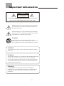
Impor tant information
Caution
Risk of electronic shock
Do not open
To reduce the risk of electronic shock, do not remove cover (or back).
No user-serviceable parts inside.
Refer service to qualified Repair Technician or Repair Center.
Read the following context indicated by the following
symbol to the left. It indicates important literature in
operating the product.
Read the following context indicated by the following
symbol to the left. It indicates a potential high voltage
hazard that may compromise your safety.
Caution
Take caution when moving the product on a cart.
Quick stops, excessive force, and uneven surfaces may
cause the display unit and cart combination to overturn.
Caution
To prevent electric shock, match wide blade of plug to wide slot,
fully insert.
Caution
This product satisfies FCC regulations when shielded cables and
connectors are used to connect the unit to other equipment.
Prevent electromagnetic interference from electrical appliances
such as radios and televisions. Please use shielded cables and
connectors for connections.
Warning
FCC Regulations state that any unauthorized changes or
modifications to this equipment not expressly approved by the
manufacturer could void the user's authority to operate this
equipment.
01
Important safety precautions
Cleaning
Stand
Remember to unplug the AC cord from the AC outlet
before cleaning the display unit. And do not use
liquid cleaners or aerosol cleaners to clean the
display.
Do not place the display unit on an unstable place.
The TV may fall resulting in serious personal
injuries to nearby people as well as damage to the
display unit.
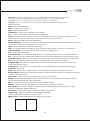
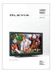
Ventilation
Do not cover or block these vents and openings located
on the top and back of the display. Inadequate ventilation
may cause overheating and shorten the lifespan of the display.
Do not place in an enclosed area such as a built-in shelf,
unless proper ventilation is provided or the manufacturer's
instructions are followed. Keep the distance of 10cm
minimum between the display unit and wall. Never install the
display unit as indicated in the picture below.
Air circulation is not blocked
Air circulation is blocked
10cm
10cm
02
Important safety precautions
Never insert objects or spill liquid
into the display unit
Precautions when transporting the
display
Never insert any object into the display unit through
openings or spill liquid on the display unit. High
voltage flows in the display unit, and inserting an
object can cause electric shock and/or short internal
parts.
Carrying the display requires two or more people.
Attachments
Keep away from water and moisture
Do not use attachments not recommended by the
manufacturer. Use of inadequate attachments may
result in accidents to nearby poeple or to the unit.
Do not place the display in areas where moisture is
present or where the unit may get wet such as bathrooms, kitchen, pool area or in a wet basement.
Power source
Keep away from heat sources
This product must operate on a power source
specified on the specification label. If you are not
sure of the type of power supply used in your home,
consult your dealer or local power company. For
units designed to operate on batteries or another
power source, refer to the operating instructions.
Keep the display unit away from heat sources such
as radiators, heaters, stoves and other
heat-generating products.
The liquid crystal panel used in this
product is made of glass
AC cord protection
Do not hit the panel. Be careful to prevent from
getting hurt by broken glass pieces in case the panel
breaks.
The AC cords must be routed properly to prevent
people from stepping on them or objects from resting
on them. Check the cords at the plugs and product.
Follow operating instructions
All operating instructions must be followed.
Wall mounting
Servicing
Be sure to install the display unit according to the
method recommended by the manufacturer. Use
only the mounting hardware recommended by the
manufacturer.
Do not attempt to service the display unit yourself
unless specified by the manufacturer.
Failure to this rule will void the warranty of the unit.
Removing covers expose you to high voltage and
other dangerous conditions.
Request a qualified service technician to perform the
service.
Overloading
Do not overload AC outlets or extension cords. It
may result in electric shock or start a fire.
03
Important safety precautions
Replacement parts
In case the display unit needs replacement parts,
make sure that the service technician uses replacement
parts specified by the manufacturer, or those with
the same characteristics and performance as the
original parts. Use of unauthorized parts can result
in fire, electric shock and/or other danger.
Safety checks
Upon completion of service or maintenance, request
the service technician to perform safety checks to
ensure that the display unit is in proper operating
condition.
Repair
When the display unit displays an abnormal
condition, any noticeable abnormality in the display
unit indicates that the display unit needs servicing.
If any of the following conditions occurs, unplug
the AC cord from the AC outlet, and request a
qualified service person to perform repairs.
1.A liquid was spilled on the display unit or objects
have fallen into the display unit.
2.The display unit has been exposed to rain or water.
3.The display unit has been dropped or damaged.
Environment
The display unit only operates within the
temperature 0C to 40 C.Operation outside of the
recommended may cause damage to your product.
04
FCC Statement
FCC notice
This equipment has been tested and found to comply with the limits for
a Class B digital device, pursuant to part 15 of the FCC Rules. These
limits are designed to provide reasonable protection against harmful
interference in a residential installation. This equipment generates, uses
and can radiate radio frequency energy and, if not installed and used in
accordance with the instructions, may cause harmful interference to radio
communications. However, there is no guarantee that interference will
not occur in a particular installation. If this equipment does cause
harmful interference to radio or television reception, which can be
determined by turning the equipment off and on, the user is encouraged
to try to correct the interference by one or more of the following
measures:
1.Reorient or relocate the receiving antenna.
2.Increase the separation between the equipment and receiver.
3.Connect the equipment into an outlet on a circuit different from that to
which the receiver is connected.
4.Consult the dealer or an experienced radio/TV technician for help.
Modifications not expressly approved by the manufacturer could void
the user's authority to operated the equipment under FCC rules. This
device complies with part 15 of the FCC Rules. Operation is subject to
the following two conditions:
1.This device may not cause harmful interference.
2.This device must accept any interference received, including
interference that may cause undesired operation.
For Canadian model
This Class B digital apparatus complies with Canadian ICES-003.
Approval
05
Accessories
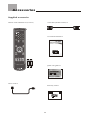
Supplied accessories
Remote control & batteries (AAA x 2)
VGA cable (D-Sub 15 male) x 1
User manual booklet x 1
LCD Multi-Media Display
LT26HVE/LT26HVX Series
Quick start guide x 1
LCD Multi-Media Display
Quick Start Guide
LT26HVE /LT26HVX Series
Power cord x 1
Warranty card x 1
06
Accessories
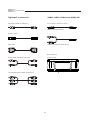
Optional accessories
Audio cable with stereo mini jack
AV cable with RCA connector
Use the proper cable for the device.
( Stereo mini jack cable )
S-video cable
DVI cable
( Stereo mini jack to RCA cable )
Wall mount set
Audio cable with RCA connector
Model# WM-20D
Component cable with RCA connector
07
TV Installation and Connection Guide
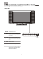
Identifying Front and Rear Panels
Front Panel
POWER Turns display on / off
MENU Displays the On Screen Display(OSD)
menu. In OSD menu, press it to return
to pre-phase
CH / CH
IR Sensor
Adjusts Channel. In the OSD menu,
both keys are used to navigate within
menu
VOL+/VOL- Adjusts volume
SOURCE Press to switch the input sources
IR SENSOR Contains Infra-red light for digital
data transmission by the remote
control. Please point remote control
at IR Sensor for function
08
TV Installation and Connection Guide
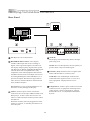
Identifying Front and Rear Connectors
Rear Panel
VIDEO
Component1
Audio Output
VIDEO-1
S-VIDEO
L
L
R
Y
ANT
Pb / Cb
VGA
R
Service
Port
S-VIDEO
AC IN power cord connects here.
VIDEO
Pr / Cr
L
R
L
R
Component2
VIDEO-2
DVI / HDCP
L
R
EarPhone
L
R
Y
Pb / Cb
Pr / Cr
(Cont'd)
The display will automatically detect the input
jack being used.
DVI/HDCP and VGA Port : This display
includes a DVI input that receives analog or
digital video signals through the interface for
the display of high quality digital video signals.
The DVI port is HDCP (High Bandwidth Digital
Content Protection) compliant and is fully
compatible with video equipment that features
the HDCP function. The VGA input can be used
for analog RGB signals from a HD Receiver or
personal computer. Resolutions supported are
VGA, SVGA, XGA and WXGA. DVI and VGA
share Audio L/R inputs.
NOTE: The S-Video input has a better quality of
picture than a composite Video signal.
Antenna (ANT) Antenna receives signals from
VHF/ UHF antennas or a cable system.
Audio Out The Audio Output sends the TV's
connected audio signals to an A / V receiver or
other equipment. Display features a R / L
stereo.
Service Port is reserved for manufacturer use.
Incorrect use may damage the Display.
Component 1, 2 These inputs can be used for the
connection of A / V equipment with component
video outputs, such as a DVD player, Digital
Satellite Receiver, or compatible Video Game
System.
Video 1,2 These inputs can be used for the
connection of a VCR, Super VHS (S-VHS) VCR,
DVD player, or other video devices to the TV.
There is a Video and an S-Video input for Video1
and Video 2.
When the S-Video jacks are plugged into either
Video 1 or Video 2, it will take precedence over
the Video jack.
09
TV Installation and Connection Guide
Descriptions of Connector Types
You may find it necessary to use some of the following connector types during setup.
75-ohm coaxial cable Used for TV cable connection .
S-Video Cable High quality video cable for enhanced picture quality.
Audio/Video Cable
Video Yellow
Audio (Left) White
Audio (Right) Red
Some DVD players are equipped with the following three video connectors:
Y- Green
Pb/Cb - Blue
Pr/Cr - Red
10
TV Installation and Connection Guide
Connecting the Power Cord
Complete other connections prior to connecting the power cord:
1.Connect the power cord to the AC IN connector of the TV
2.Connect the other end of the power cord to the wall outlet.
11
TV Installation and Connection Guide
Installation
In the following pages, you will find directions on how to install your tv and choice of video equipment.
Connecting to an Antenna or Video Equipment with Antenna outlet
Connecting to a VCR
Connecting to an Audio Receiver/Home Theater System
Connecting to a DVD Player with A/V or S-Video Cables
Connecting to a DVD Player with Component Cables
Connecting to a Satellite Receiver or Cable Box with A/V Cables
Connecting to a Satellite Receiver or Cable Box With Component Connectors
Connecting to a PC with VGA, and a DVD Player with DVI / HDCP Cables
Other Connections
12
TV Installation and Connection Guide
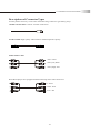
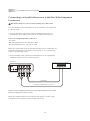
Connecting to an Antenna or Video Equipment
with Antenna outlet
Disconnect all power sources before making any connection.
1.Connect a 75ohm coaxial cable onto the ANT input on the back of the
TV's right side panel.
Rear of TV
R
L
VIDEO
Component1
Audio Output
VIDEO-1
S-VIDEO
Y
ANT
Pb / Cb
S-VIDEO
VIDEO
Pr / Cr
L
R
L
R
Component2
VIDEO-2
L
R
EarPhone
L
R
Y
Pb / Cb
Pr / Cr
75-ohm coaxial cable
If connecting to Video Equipment with Antenna outlet
1.Using a 75-ohm coaxial cable (or choice of Antenna Cable), connect
the cable box's OUT jack to the TV's ANT jack (RF Terminal).
Rear of TV
VIDEO
Component1
Audio Output
VIDEO-1
S-VIDEO
L
R
Y
ANT
Pb / Cb
S-VIDEO
IN
jack
VIDEO
L
R
OUT
jack
75-ohm coaxial cable
75-ohm coaxial cable
Video Equipment with
Antenna In/Out Socket
13
Pr / Cr
L
R
L
R
Component2
VIDEO-2
EarPhone
L
R
Y
Pb / Cb
Pr / Cr
TV Installation and Connection Guide
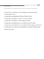
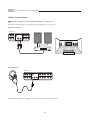
Connecting to a VCR
Disconnect all power sources before making any connections.
Use this hookup if you subscribe to a cable TV system that does not
require a cable box.
1.Using A/V cable and S-Video cables, connect the VCR's Audio and S Video
OUT jacks to the TV's Audio and S-Video In jacks.
VCR
Rear of TV
S-VIDEO
VIDEO
Component1
Audio Output
VIDEO-1
L
R
Y
ANT
Pb / Cb
S-VIDEO
VIDEO
Pr / Cr
L
R
L
R
Component2
VIDEO-2
L
R
EarPhone
L
R
Y
Pb / Cb
Pr / Cr
A/V cable with RCA connector
S Video cable
Connecting both Video IN or S-Video IN
Note: Use this method of connection if you subscribe to a cable TV
system that does not require a cable box.
S-Video is strongly recommended for use if your VCR or video
equipment has it. S-Video input has a better quality of picture than a
composite Video signal.
Note: You can also use the Video 2 jacks located on the TV rear to
connect additional video equipment.
14
TV Installation and Connection Guide
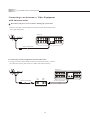
Connecting to an Audio Receiver / Home Theater System
Disconnect all power sources before making any connections.
1.Using an audio cable, connect the TV's audio OUT jack to the audio
receiver's audio IN or AUX IN jacks.
Rear of TV
Audio Receiver
VIDEO
Component1
Audio Output
VIDEO-1
S-VIDEO
L
R
Y
ANT
Pb / Cb
S-VIDEO
VIDEO
L
EarPhone
R
White
Audio cable
Note: When connecting an Audio output signal, an external Audio
amplifier is necessary to amplify the signal for external speakers.
Note: If the audio out is hooked up to a home theatre sound system,
please disable the audio in the OSD by selecing off in audio section .
Volume adjustment must be made on the home theatre receiver. By not
disabling the TV's speaker it could damage the speakers or TV itself.
15
Pr / Cr
L
R
L
R
Component2
VIDEO-2
L
R
Y
Red
Pb / Cb
Pr / Cr
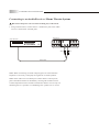
TV Installation and Connection Guide
Connecting to a DVD Player with A/V or S-Video Cables
Disconnect all power sources before making any connections.
Note: Use this method of connection if your DVD player does not have
component (Y, Pb,Pr) jacks.
Note: If your DVD player has component video output connectors, for
best picture quality, use the connection described for Connecting to a
DVD Player With Component Connectors.(See page.17)
1.Using an A/V cable, connect the DVD player's Audio OUT jacks to
the TV's Audio IN jacks.
2.Using an S-Video Cable, connect the DVD player's S-Video OUT jack
to the TV's S-Video IN jack.
DVD player
Rear of TV
S-VIDEO
VIDEO
Component1
Audio Output
VIDEO-1
L
R
Y
ANT
Pb / Cb
S-VIDEO
VIDEO
Pr / Cr
L
R
L
R
Component2
VIDEO-2
L
R
EarPhone
L
R
Y
Pb / Cb
Pr / Cr
A/V cable with RCA connector
S Video cable
Note: S-Video is strongly recommended for use if your VCR or video
equipment has the option .S-Video input has better quality of picture than a
composite Video signal.
Note: You can also use the Video 2 jacks located on the TV rear to
connect additional video equipment.
16
TV Installation and Connection Guide
Connecting to a DVD Player With Component Cables
Disconnect all power sources before making any connections.
Note: Use this method of connection if your DVD Player has component
(Y, Pb, Pr) jacks.
1.Using a component video cable, connect the DVD Player's Y, Pb and
Pr jacks to the Y, Pb and Pr jacks on the TV.
Colors on Component Video connectors:
Y: Green
Pb (also identified as Cb, CB or B-Y): Blue
Pr (also identified as Cr, CR or R-Y): Red
Note: The Y, Pb and Pr jacks on your DVD player are sometimes labeled
as Y, Cb and Cr, or B-Y and R-Y. If so, connect the cables to the
matching colors.
2.Using an Audio cable, connect the DVD player's Audio OUT jacks to
the TV's Audio in jacks.
Rear of TV
S-VIDEO
VIDEO
DVD player
Component1
Audio Output
VIDEO-1
L
R
Y
ANT
Pb / Cb
S-VIDEO
VIDEO
Pr / Cr
L
R
L
R
Component2
VIDEO-2
L
R
EarPhone
L
R
Y
Pb / Cb
Pr / Cr
Audio cable
Component cable with RCA connector
Note: The Y, Pb and Pr jacks do not provide audio, so audio cables must
be connected to provide sound.
Note: The YPbPr connection provides the best quality of video signal
compared to AV (Composite) and S-Video connection.
17
TV Installation and Connection Guide
Connecting to a Satellite Receiver or Cable Box with A/V Connectors
Disconnect all power sources before making any connections.
1.Using Audio and S Video cables, connect the satellite receiver's Audio
and S Video OUT jacks to the TV Audio and S Video IN jacks.
2.Connect a 75-ohm coaxial cable from your cable or antenna to the TV
Ant (Antenna) jack.
75-ohm coaxial cable
Rear of TV
S-VIDEO
VIDEO
L
R
Y
ANT
Pb / Cb
VIDEO
Pr / Cr
L
R
L
R
Component2
VIDEO-2
S-VIDEO
Satellite Receiver or Cable Box
Component1
Audio Output
VIDEO-1
L
R
EarPhone
L
R
Y
Pb / Cb
Pr / Cr
A/V cable with RCA connector
S Video cable
Note: S-Video is strongly recommended for use if your VCR or video
equipment has it because S-Video input has better quality of picture than
a composite Video signal.
Note: You can also use the Video 2 jacks located on the TV rear to connect
additional video equipment.
18
TV Installation and Connection Guide
Connecting to a Satellite Receiver or Cable Box With Component
Connectors
Disconnect all power sources before making any connections.
Use this hookup if your Satellite Receiver or Cable Box has component
(Y, Pb, Pr) jacks.
1.Using a component video cable, connect the Satellite Receiver or
Cable Boxes' Y, Pb and Pr jacks to the Y, Pb and Pr jacks on the TV.
Colors on Component Video connectors:
Y: Green
Pb (also identified as Cb, CB or B-Y): Blue
Pr (also identified as Cr, CR or R-Y): Red
Note: The Y, Pb and Pr jacks on your Satellite Receiver or Cable Box are
sometimes labelled as Y, Cb and Cr, or B-Y and R-Y. If so, connect the
cables to the matching colors.
2.Using an Audio cable, connect the Satellite Receiver or Cable Boxes'
Audio OUT jacks to the TV's Audio in jacks.
Rear of TV
S-VIDEO
VIDEO
Satellite Receiver or Cable Box
Component1
Audio Output
VIDEO-1
L
R
Y
ANT
Pb / Cb
S-VIDEO
VIDEO
Pr / Cr
L
R
L
R
Component2
VIDEO-2
L
R
EarPhone
L
R
Y
Pb / Cb
Pr / Cr
Audio cable
Component cable with RCA connector
Note: Use this method of connection if your Satellite Receiver or Cable
Box has component (Y, Pb, Pr) jacks.
Note: The YPbPr connection provides the best quality of video signal
compared to AV (composite) and S-Video connection.
19
TV Installation and Connection Guide
Connecting to a PC with VGA
Connector
Rear of TV
L
DVI / HDCP
Disconnect all power sources before making
any connections.
VGA
R
1.Using a D-Sub 15 pin cable, connect the VGA
output terminal of the PC to the TV's VGA signal
input terminal.
2.You may need to use a Stereo mini jack to RCA
L/R connectors to receive audio.
Red
D-sub 15 pin cable
Connecting to a DVD Player or HDReceiver with a DVI/HDCP Cable
Service
Port
White
Rear of TV
L
Disconnect all power sources before making
any connections.
1.Using a DVI cable, connect the DVD's DVI output
terminal to the TV's DVI-HDCP input terminal.
2.Using an Audio cable, connect the DVD's Audio
OUT jacks to the TV's Audio IN jacks.
DVI / HDCP
VGA
R
Red
Note: VGA and DVI/HDCP Connectors share the
same audio input.
DVI cable
Note: HDCP is a copy protected digital connection
that receives analog or digital video signals from
equipment with DVI ouput that features the HDCP
function. DVI allows the transfer of digital
uncompressed data to the TV.
DVI technology is better than Component, S Video
or AV (composite) connections.
Note: DVI signal is purely digital and provides a
crystal clear technology better than component,
S-Video or Video connections. It is strongly
recommended to use this connection if you have
this function on your equipment.
20
Service
Port
White
Audio cable with
stereo mini jack
TV Installation and Connection Guide
Other Connections
Disconnect all power sources before making any connections.
See setup instructions for: Connecting to an Audio Receiver on page 15.
Speakers Outputs
Rear of TV
S-VIDEO
VIDEO
Component1
Audio Output
VIDEO-1
L
R
Y
ANT
Pb / Cb
S-VIDEO
VIDEO
Pr / Cr
L
R
L
R
Component2
VIDEO-2
L
R
EarPhone
L
R
Y
Pb / Cb
Pr / Cr
Headphone Set
Rear of TV
VIDEO
Component1
Audio Output
VIDEO-1
S-VIDEO
L
R
Y
ANT
Pb / Cb
S-VIDEO
VIDEO
Pr / Cr
L
R
L
R
Component2
VIDEO-2
L
R
EarPhone
L
R
Y
Pb / Cb
Pr / Cr
Note: When headphone is plugged in the speaker will turn into mute mode.
21
Remote Control Guide
Remote Function Keys & Description
Regular Buttons
POWER Press to turn display on/off.
CH + / CH- Press to adjust channel up and
channel down.
NUMBER BUTTONS Press the number buttons
to select channels on the display.
1
VOL+/ VOL- Press to adjust the volume.
2
3
RETURN (Channel Return) Press to return the
to previous-channel.
4
5
MTS Press to select from SAP, Mono or Stereo
mode
buttons (Direction Buttons) Press to
move highlighted selection through menus or
submenus.
SOURCE Press to show the source input from
TV 1, AV 1, AV 2, SV 1, , SV 2, YPbPr 1,
YPbPr 2, DVI and VGA.
9
6
10
7
11
8
12
ENTER Press to enter the channel number,
highlighted menu or submenu item.
13
MUTE Press to mute the sound.
MENU Press to activate or close the On Screen
Display menu. In OSD Menu, acts as a cancel
button while navigating through the OSD.
DISPLAY Press to display the information of
current channel number and time.
Hotkeys Press to directly access certain
Shortcut TV functions..
22
Remote Control Guide
Hot Keys Tutorial
The remote control contains 15 additional "Hotkeys" that represent
direct access to a certain function on your TV. Hotkeys enable you to
directly change the setting to your preference without having to
navigate through the OSD (On Screen Display) Menu.
How to use your Hot Keys
HOT KEY FUNCTION
TV / VIDEO Press to select a video signal from different sources (TV 1
, AV 1, AV 2, SV 1, , SV 2, YPbPr 1, YPbPr 2, DVI and VGA ) .
AUTO ( Auto adjustment ) Under VGA mode, the screen position
could be automatically adjusted by pressing "Auto" button, when the
screen image is not centered.
VIEW Press to select and program PIP, Split Screen or viewing options.
SWAP Press to select TV channels between main and sub screen. (This
function is only in the PIP and Split Screen modes. )
EQ1 This function will provide an environmental effect to the audio for
an added live experience.
FAVORITE Press to select favorite channels. Can be preset in OSD
Menu.
C.C. Press to call up the Close Caption (CC) and Caption Service (CS)
list. You can pre-select one to see Closed Caption.
EQ2 This function will provide a preset equalized effect to the audio for
added audio definition.
Note: EQ1 and EQ2 selections can be used simultaneously to suite your
preference.
23
Remote Control Guide
Battery Installation
1.Push the tab and pull it out as illustrated below.
2.Insert two size AAA batteries (supplied) by matching the (+) and (-)
on the batteries to the diagram inside the remote control's battery
department.
3.Replace the cover back and make sure the cover "snaps" into the
remote control.
Note:
1.The display unit comes with two new AAA batteries as accessories.
However, due to uncontrollable causes, the electricity of the
accessorized batteries may be partially or completely drained. We do
not warrant the quality of the batteries in any case since many factors
are considered. If replacement is needed, please purchase two AAA
batteries.
2.Handle remote with care. Avoid dropping it, placing in direct sunlight,
near a heater, high areas of humidity or getting it wet. If the remote
gets wet, please wipe it dry immediately. In the event of the remote
not working properly or is inoperational, a replacement of remote
control may be required.
3.If you do not use the remote control for a long period of time, please
remove the batteries and store in a cool place to preserve battery life.
4.Do not mix new and used or with different types of batteries for
operation.
24
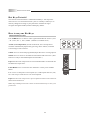
Adjusting On Screen Displays (OSD)
Introduction
After you have finished connecting your TV, you are now ready to choose
and personalize your TV settings in the OSD (On Screen Display) menu.
There are four main sections in the OSD Menu:
Video
Audio
Miscellaneous
Screen
To Operate in the OSD
1. Press "Menu" button to enter OSD menu mode.
2. In Main OSD Menu, use the and keys to select and enter each
main OSD Section: Video; Audio; Miscellaneous; Screen.
Note: The OSD Section appears at the bottom left corner of the OSD
Screen at all times.
3. In Each OSD Section, press the and to select the function, and
the
button to make an adjustment or selection.
4. To adjust the value bar, use the keys
and
5. After choosing your setting, press the to go back into Main OSD
Section. To exit, press
to go back to Main OSD Menu.
6. To exit the OSD menu, press "Menu" until you exit the OSD menu,
or without action for 12 seconds of inactivity. This is also
adjustable in the OSD.
25
OSD-Video
Adjusting On Screen Displays (OSD)
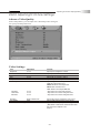
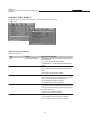
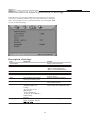
VIDEO Adjusting TV Picture Settings
Advance Video Quality
In this Setup Index, you can adjust the video and picture settings to
suit your personal preferences.
Video Settings
Item
Brightness
Contrast
Saturation
Hue
Sharpness
Color temp
Red Gain
Green Gain
Blue Gain
Backlight
Auto Setting
Advance Picture Setting
Adjustment
0~100
0~100
0~100
0~100
0~100
Cool / Middle / Warm / User
0~100
0~100
0~100
Bright / Middle / Dark
Enter
Enter
Function
Adjusts picture brightness contrast
Adjusts picture color contrast
Adjusts the color intensity
Adjusts the tint or shade of picture
Adjusts the picture sharpness or softness
Adjusts image color intensity.
Cool: More blue-tinted colors
Middle: Standard color temperature
Warm: More red-tinted colors
User: Allows User to adjust RGB Gain
Adjusts the color control with red tones
Adjusts the color controls with green tones
Adjusts the color controls with green tones
Adjusts the darkness or lightness of the screen
Adjusts OSD Settings back to factory default
Adjusts additional specific picture settings
( DNR, Black Level Extender, White Peak Limitator,
CTI, Flesh Tone, Adaptive Luma
Control )
26
OSD-Video
Adjusting On Screen Displays (OSD)
Advance Video Adjust
To further adjust specific picture settings, enter this function by pressing
the button.
Advance picture setting
Definition of Terms
Item
DNR
Status
Off/Low/Middle/Strong
Black Level Extender
On/Off
White Peak Limitator
On/Off
Flesh Tone
On/Off
Adaptive Luma Control
On/Off
Description and Function
DNR-Dynamic Noise Reduction. Reduces high frequency
noise dynamically.
Off- Dynamic Noise Reduction is disabled.
Low/Middle/Strong---Set the DNR in low/medium/strong
degree.
Black Level Extender -Extends "grays" to black so a
more accurate picture is produced with a wider contrast
scale.
On-The Black Level Extender is enabled.
Off-The Black Level Extender is disabled.
White Peak Limitator-Limit the signal amplitude varying
degree resulted in frequency increasing or other reasons,
and in case of screen defocus for white-peak.
On-The White Peak Limitator is enabled.
Off-The White Peak Limitator is disabled.
Most LCD TV's video processing solutions have a red push
to the their color matrix. With the Flesh Tone Control option,
it helps to tone down these strong reds and produce more
naturalistic color tones.
On-Flesh tone adjustment is enabled.
Off-Flesh tone adjustment is disabled.
Control the luminance adaptively.
On-The Adaptive Luma control feature is enabled.
Off-The Adaptive Luma control feature is disabled.
27
OSD-Vidio
Adjusting On Screen Displays (OSD)
To Adjust S ettings:
Use the and
as seen below:
remote buttons to adjust each Video picture setting,
Brightness
Saturation
Hue
To exit, press the
Button
To Reset Factory Settings
If, at any time, you wish to go back to original factory setting, you may
do so by choosing the Default setting in the OSD Picture and Audio Sections.
Selecting "Default," will reset all OSD settings to the original
manufacture settings. The only items which will remain unaffected, are:
Clock
Auto Scan Channels
Edited Channels
Parental Control Password
28
OSD-Audio
Adjusting On Screen Displays (OSD)
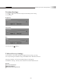
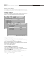
Audio Adjusting Sound Quality
Audio setting
Definition of Terms
Item
Treble
Bass
Balance
Surround
Adjustment
-50~50
-50~50
-20~20
On / Off
Equalizer 1
MTS
Off, Concert, Living Room,
Hall, Arena, Church
Off, Rock, Pop, Live, Classic,
Soft
Mono, Stereo, SAP
Speakers
On / Off
Equalizer 2
Function
Adjusts higher pitched sounds
Adjusts lower pitched sounds
Adjusts volume balance in Left and Right
Creates a panoramic stereo audio image by producing
deep and rich bass tones and clear treble tones. This
enables you to enjoy powerful sound effects like those
in a movie theatre
Adjusts the sound as occurred in an enclosed space
of varying spaces
Adjusts the volume of different bands (ranges of
frequencies (HZ)) to control the overall sound
Adjusts sound reception of stereo, bilingual and mono
programs under the TV Source.
Turns off the speakers of the TV when using a
Receiver or Home Theater System.
29
OSD-Audio
Adjusting On Screen Displays (OSD)
To Adjust Settings:
Use the and
seen below:
remote buttons to adjust each Audio sound quality, as
Treble
Bass
Balance
Surround Sound is an available option for creating a panoramic stereo
audio image by producing deep and rich bass tones and clear treble
tones. This enables you to enjoy powerful sound effects like those in a
movie theater.
Speakers
Must turn off speakers of the TV when using a Receiver or Home
Theater System.
30
OSD-Audio
Adjusting On Screen Displays (OSD)
OSD Audio Settings: Equalizer 1
OSD Audio Settings: Equalizer 2
31
OSD-Audio
Adjusting On Screen Displays (OSD)
MTS System for Stereo TV
You can enjoy stereo, bilingual and mono programs.
Additionally, you can press the hotkey "MTS" until the desired sound in
dication appears. Each time you press the button, the sound indication
changes as follows:
Mono, Auto SAP, Stereo
Definifion of Terms
Sound Effect
Stereo
Auto SAP
Mono
Description
Select for stereo reception when viewing a program broadcast
in stereo
Select to automatically switch the TV to Secondary Analog
Program when a signal is received.
(If no SAP signal is present, the TV remains in Stereo Mode)
Select for mono reception.
(Use to reduce noise during weak stereo broadcasts)
32
OSD-Miscellaneous
Adjusting On Screen Displays (OSD)
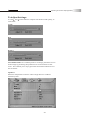
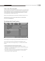
MISCELLANEOUS Adjusting Personal TV Settings
In this Section, you can adjust additional TV settings to your personal
preference, including channel setup, choosing tuner modes, setting up
timer, closed caption services, parental controls, and viewing the OSD
in your preferred language.
Description of Settings
Item
Channel Setup
Channel-Favorite
Channel-Skip
Channel-Name
Tuner Mode
Auto Search
Timer
Closed Caption
Parental
Language
Adjustment
Function
Setting up Channel functions
Stores the favorite channels
Sets up available channels.
Add : To add available channel.
Skip : To cancel available channel
Stores channel names
24 favorite channels setting
Air / Cable
Selects to auto scan the available channels
of the TV or CATV.
Set Alarm with channel preference
Time, Start/Stop Time, Channel,
Activate option, Display option
C1, C2, C3, C4, T1, T2, T3, T4
Switches different types of caption or
cancel caption functions.
Adjusts MPAA and TV Ratings under parental
control settings and setup password lock.
MPAA
G/PG/PG-13/R/NC-17/X
Tv rating
TV-Y/ TV-Y7/ TV-Y7-FV
NPAA Unrated
TV-G/ TV-PG(V,S,L,D)/
TV-14(V,S,L,D) / TV-MA(V,S,L)
TV None Rating
Password
English / Deutsch / Francais / Espanol
Italiano / Portugues / Svenska
/
Switches the OSD language
Default
Resets OSD setting to default.
33
OSD-Miscellaneous
Adjusting On Screen Displays (OSD)
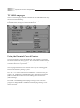
Setting the Channels
After you finish connecting your TV, you can run Auto Scan program to
setup your channels. The program will scan and preset all receivable
channels automatically.
To Cancel Auto Program
Exit auto scan program by pressing "menu" Key.
Note: The Auto Scan is set to scan cable TV channels by default. You
cannot receive and set the cable TV channels VHF/ UHF channels
at the same time.
Setting Favorites Channels
You can select and store a list of your favorite channel settings.
Selected favorite channels are marked with a
icon.
You can preset favorite channels on this page. You can also access
this function by pressing the " FAVORITE" hotkey on the remote
control and select or switch between your favorite channels .
1. Enter "Channel-Favorite" mode.
2. Press "Edit " to enter the channel(s) using the number keys.
You can "Delete" channels per line or "Empty" all channels at once.
3. Press "View" to see the selected channel display in real time.
4. Press "Enter" to exit when complete.
34
OSD-Miscellaneous
Adjusting On Screen Displays (OSD)
Watching favorite channels
To watch you favorite channels after specifying your preferences, just
press the Hotkey "FAVORITE" to browse through each favorite channel.
Editing Channels
You can also edit channels to your personal preference. Once you edit a
channel, it will be skipped when surfing through TV channels.
To Skip or Lock a Channel
1.Make sure Channel Skip or Channel Lock is highlighted.
2.Enter the channel number you wish to skip or lock, or scroll through
channels using the and
Arrow.
3.Press "Enter" to make your selection or adjustment.
Note: You will see a checkmark next to Skipped Channels, and a small
lock icon next to Locked Channels.
4.Press to exit when complete.
To Undo a Skipped or Locked Channel:
1.Make sure Channel Skip or Channel Lock is highlighted.
2.Enter channel number you wish you undo, or scroll through channels
using the and Arrow.
3.Press "Enter" to make your selection or adjustment.
Note: You will NOT see a checkmark next to Skipped Channels, or a
small lock icon next to Locked Channels afterwards.
4. Press to exit when complete.
35
OSD-Miscellaneous
Adjusting On Screen Displays (OSD)
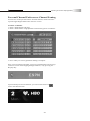
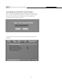
Personal Channel Preferences: Channel Naming
You can also create personal names for each channel, which will show
up in the upper Right hand corner of the TV screen.
To Name a Channel:
1. Enter Channel Name sub-page
2. Enter Channel name using alphabet-numerical keypad as seen below:
3. Press "Okay" to exit keypad when naming is complete.
Once you have named a channel, your preset channel name will show up
on the TV screen when flipping through channels, or by pressing the
Display Key.
If you named your favorite channel, you will see the heart icon
next to the channel name.
36
OSD-Miscellaneous
Adjusting On Screen Displays (OSD)
Setting up the TV Timer
To setup the time on the TV:
1.Using and
keys, enter in HH: MM: SS Enter the time using the
number keys found on the remote.
2.press "Enter" when complete.
NOTE: Clock will NOT BE affected when Factory Default settings are
reset.Under Activate, "ON" allows the start/stop time to be ongoing
whereas, "ONCE" allows it to only function once.
However, when the power cord is not connected to the TV, you will lose
all previous time adjustments.
37
OSD-Miscellaneous
Adjusting On Screen Displays (OSD)
Timer: Start Time / Stop Time
You can set the TV to turn On and/or Off automatically at a predetermined
time through the timer function. Use the Start Time to setup the hour and
minute preferences. Your TV will automatically turn on at the set time.
Use the Stop Time to setup the hour and minute preferences. Your TV
will automatically turn off at the set time.
Note: Alarm WILL BE affected when Factory Default settings are reset.
When the power cord is not connected to the TV, you will lose all
previous saved adjustments.
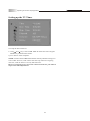
Watching with Closed Caption
You can display closed captioning if the broadcaster offers this service.
Close Caption option can be set On/Off from the OSD page. This
function also can be accessed by pressing "C.C " hotkey on the remote
control.
1. Not all programs offer the Closed Caption option.
2. Closed Caption may not be seen clearly (white blocks, strange
characters, etc.) if the signal condition is poor, or if there are technical
difficulties with the broadcaster.
3. If no TEXT broadcast is being received while viewing in the [TEXT]
mode, the screen may become dark and blank for some programs.
Switch Off the Closed Caption mode.
38
OSD-Miscellaneous
Adjusting On Screen Displays (OSD)
TV OSD Languages
There are nine language formats available for the OSD Menu. You may
choose from the following:
English, Chinese Traditional, Chinese Simplified, Spanish,
French, German, Portugese, Italian and Russian.
Using the Parental Control Feature
To block programs you feel unsuitable for your children, you need to
Set the TV for desired rating systems. The TV Parental Control feature
functions by receiving the rating signal from your local broadcasting
station or cable service provider.
The TV programs and movies shown on TV are given a rating signal
based on the following rating systems.
In U.S.A.: U.S. Television Parental Guidelines to rate television pro
grams (U.S. TV Ratings) and Motion Picture Association of America
(MPAA) Guidelines to rate movies including those shown on TV
(Movie ratings).
In Canada: Canadian English Language ratings to rate television
programs in English, and Canadian French Language ratings to rate
those in French.
39
OSD-Miscellaneous
Adjusting On Screen Displays (OSD)
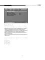
Parental Control
1. This function allows programs to be restricted and controlled by
parents based on FCC regulation. It prevents children from watching
program contents that may be prohibited by parents.
2. Restriction of programs is based on three Rating Systems: MPAA
Rating, TV (Child) Rating and TV (Entire Audience) Rating.
The MPAA Rating restricts based on age. TV (Child) rating and TV
(Entire Audience) Rating restrict based on age and contents.
3. When you block the lower rating, the higher age-based ratings are
blocked automatically.
4. When you enter "Parental control" mode, those messages display for
different state.
The Parental Control Main Menu contains four options in the following
categories:
1.MPAA Rating
2.TV Rating
3.MPAA Unrated
4.TV Unrating
40
OSD-Miscellaneous
Adjusting On Screen Displays (OSD)
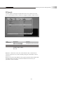
Activating the Parental Control Feature
Once you enter the highlighted section of Parental Control, you will
have to enter your password. The Factory Default password is"9999".
Once you enter the Parental Control Menu, you may change the
password to your personal preference.
To setup, enter each sub-menu to setup your parental controlled TV
channels.
41
OSD-Miscellaneous
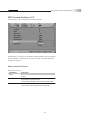
Adjusting On Screen Displays (OSD)
MPAA Rating controls channels and movies that are rated from G,
PG-13, R, NC-17, and X.
TV Rating controls channels and movies that have been rated from TV-Y,
TV Y-7, TV-G, TV-PG, TV-14, and TV-MA.
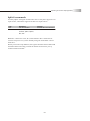
To Block Unrated Channels
You may choose "YES" for Block MPAA Unrated and Block TV None
Rating. This will lock you from accessing any channels that do not
contain MPAA or TV Ratings. To watch unrated channels, re-activate
Block MPAA Unrated and Block TV None Rating to "NO".
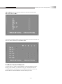
42
OSD-Miscellaneous
Adjusting On Screen Displays (OSD)
Setting up Parental Control Password
Enter the password sub-page. Enter the current password. If this is the
first time, you do not have to enter a password.
You will have to enter and confirm your password before changing to a
new password. Please keep password within 4 numbers.
If you enter the incorrect password, you will see an error page.
Please re-enter the new password and confirmation password again.
Note: If you forget the password, press "9999" to lift the Password lock
and change to a new preferred password.
43
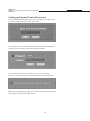
OSD-Miscellaneous
Adjusting On Screen Displays (OSD)
Factory Default Option
Reset Factory Settings:
Initiating Factory Default will reset all OSD settings to original
manufacture settings. The only items, which will remain unaffected are:
Clock
Auto Scan Channels
Edited Channels
Parental Control Password
44
Adjusting On Screen Displays (OSD)
Adjusting Screen Modes
There are two option in the Screen Modes, "aspect & "View." Apect will
allow user to select different aspect ratios, whereas, View will all
different modes of viewing 1 or 2 sources.
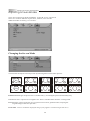
Changing the Screen Mode
You can alter the aspect ratio of a picture by choosing between these four options:
Input
4:3
Input
16:9
Full Screen
4:3
16:9
Panoramic
Full Screen Enlarges the picture to 16:9 wide mode, by stretching the picture horizontally only.
4:3 Returns the 4:3 picture to its original size. This is considered the "normal" viewing mode.
16:9 Enlarges (zoom-in) the size of a 4:3 picture on screen as geometric ratio, keeping the
original image as much as possible.
Panoramic select to widen the displayed image. (only applies to content larger than 16:9)
45
OSD-Screen
Adjusting On Screen Displays (OSD)
Changing the View Modes
You can select four view types of picture modes that best suits the
program you are watching. You can set a different view mode for each
video mode for each input and store it manually.
View Modes
Function
PIP
Picture-in-Picture has a Main screen and small screen view
Split Screen
Full Screen split in two Views
Picture in Picture (PIP)
Allows you to view a main screen (Picture 1)and a secondary small
screen (Picture 2).
Press 'source' button to switch from P1 to P2 and vice versa.
You may also choose the settings of P1 and P2 as well as the position
of P2 on screen.
46
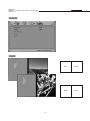
OSD-Screen
Adjusting On Screen Displays (OSD)
OSD View
TV View
47
Pic1
Pic2
Pic1
Pic2
OSD-Screen
Adjusting On Screen Displays (OSD)
PIP mode
You may adjust setting for each Picture source. Pic 1 allows for a TV,
AV1, AV2 and DVI sources while Pic 2 supports all other input sources.
Item
PIP Position
PIP-Pic1
PIP-Pic2
Adjustment
Upper Left / Upper Right /
Lower Left / Lower Right
TV1,AV1, AV2, DVI
AV1, AV2, S-Video1,
S-Video2, YpbPr1, YpbPr2,
DVI, VGA
Function
Changes the position of Picture 2
Switches the source of Picture 1
Switches the source of Picture 2
Note: Pic 1 allows for a TV, AV1, AV2 and DVI. Pic 2 allows for all
sources except TV or if you are already using one of the other sources
from Pic 1.
When you use the swap function, the signals from the main window and
the PIP window will swap positions no matter what sources you
specified on either window.
48
OSD-Screen
Adjusting On Screen Displays (OSD)
Split Screen
Allows you to view two separate screens simultaneously (Picture 1 and
Picture 2).
Press 'source' button to switch from P1 to P2 and vice versa.
OSD View
TV View
49
Pic1
Pic2
Pic1
Pic2
Adjusting On Screen Displays (OSD)
Split Screen mode
You may adjust setting for each Picture source. Only Pic1 supports a TV
input source, while Pic2 supports all other TV input sources.
Item
Pic1
Pic2
Adjustment
TV1, AV1, AV2, DVI
AV1, AV2, S-Video1,
S-Video2, YpbPr1, YpbPr2,
DVI, VGA
Function
Switches the source of Picture 1
Switches the source of Picture 2
Note: Pic 1 allows for a TV, AV1, AV2 and DVI. Pic 2 allows for all
sources except TV or if you are already using one of the other sources
from Pic 1.
When you use the swap function, the signals from the main window and
the PIP window will swap positions no matter what sources you sp
ecified on either window.
50
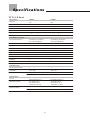
Specifications
TFT LCD Panel
Specificatinos
LT26HVE
LT26HVX
Panel size
26in
26in
Aspect Ratio
15:9
16:9
Pixels
1280 X 768
1366 X 768
Brightness
7 00 cd/ m 2
80 0 cd / m 2
Contrast
750:1
1200:1
H/V(View Angle)
170 (H) / 170 (V)
178 (H) / 178 (V)
Gray to Gray Response Time
12 ms
8 ms
PC compatible frequency
30~85 KHz(H) / 50~80Hz(V)
Max. 1280x1024 @60Hz
30~85 KHz(H) / 50~80Hz(V)
Max. 1280x1024 @60Hz
NTSC
Video/Graphic Processing
Video Compatibility
NTSC
DTV & HDTV Compatability
480i, 480p, 720p, 1080i
480i, 480p, 720p, 1080i
Aspect Ratio Adjustment
Full Screen, 4:3, 16:9, Panoramic
Full Screen, 4:3, 16:9, Panoramic
3D Comb Filter
Y
Y
3 2 / 2 : 2 Pull D own
Y
Y
Digital Noise Reduction
ON / OFF, High, Low
ON / OFF, High, Low
Adjustable Color Temperature
Y
Y
De-interlacer
Y
Y
VGA Auto Frequency Correction
Y
Y
TV Auto Frequency Detection
Y
Y
Audio Processing
Auto Sound Level Control
Y
Y
Output Watt
10W + 10W
10W + 10W
Sound Effect
MTS (Mono / Stereo / SAP)
MTS (Mono / Stereo / SAP)
EQ1 andEQ2
EQ1 andEQ2
TV Tuner
NTSC VHF/UHF tuner x1
NTSC VHF/UHF tuner x1
Video Input(rear side)
AV1, Svideo1, RL x1
AV2, S-Video2, RL x1
Y Pb/Cb Pr/Cr x2, RLx2
AV1, Svideo1, RL x1
AV2, S-Video2, RL x1
Y Pb/Cb Pr/Cr x2, RLx2
Graphic Input(Rear)
Input 1: RGB D-Sub 15 pin x1, RLx1
Input 1: RGB D-Sub 15 pin x1, RLx1
Input Terminals
Service Port(Rear)
Input 2: DVI-D(w/ HDCP) x1
Input 2: DVI-D(w/ HDCP) x1
RS-232 mini DIN 6 pins X 1
RS-232 mini DIN 6 pins X 1
51
Specifications
TFT LCD Panel
Output Terminals
LT26HVE
LT26HVX
Audio Output(Rear)
Output 1:Earphone X 1
Output 1:Earphone X 1
Output 2:RCA, R/L X 1
Output 2:RCA, R/L X 1
Others
Power
(Voltage)
100~240 VAC / 50-60 Hz
100~240 VAC / 50-60 Hz
(Power Consumption)
130W
130W
Stand-by
< 3W
< 3W
Dimensions (W x D x H)
33.46 in x 19.6 in x 8.93 in
33.46 in x 19.6 in x 8.93 in
Weight w/ stand
30.86 lbs
34.82 lbs
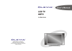
Dimensional drawing
4.41in
18in
19.6in
8.93in
13.5in
33.46in
52
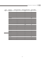
Timing Mode for VGA and DVI
Source
Resolution
YPbPr
480p
59.94
31.469
27
720p
60
45
74.25
1080i
60
33.75
74.25
512 x 384
60.147
24.48
15.667
640 x 350
85
37.861
31.5
640 x 400
85
37.861
31.5
56
24.823
21.05
59
30.296
24.964
59
30.295
25.024
66
35
30.24
66
34.975
31.34
66
35
30.24
72
37.861
31.5
75
37.5
31.5
75
39.375
31.5
85
43.269
36
720 x 350
70
31.469
28.32
720 x 400
70
31.469
28.32
85
37.927
35.5
87
39.444
35.5
56
35.156
36
60
37.879
40
72
48.077
50
75
46.875
49.5
85
53.674
56.25
832 x 624
74.6
49.725
55
1024 x 768
59
48.193
64
60
47.699
64.1
60
48.363
65
70
56.476
75
70
56.287
77
71
57.87
75
75
60.241
80
VGA
640x480
800 x 600
Vertical frequency(Hz)
Horizontal frequency (Khz)
53
Pixel rate (MHZ)
Timing Mode for VGA and DVI
Source
Resolution
VGA
1024 x 768
Horizontal frequency (Khz)
Pixel rate (MHZ)
75
60.241
80
75
62.937
84.6
75
61.08
86
75
60.023
78.75
77
62.04
84.4
85
68.677
94.5
70.012
63.851
94.5
75
67.5
108
1152 x 870
75.062
68.681
100
1152 x 900
65.95
61.795
92.9
66.004
61.846
94.5
76.047
71.713
105.6
76.149
71.809
108
60
63.36
89.2
61.399
65.286
92.9
1280x 960
60
60
108
1280 x 720
60
45
74.25
1280 x 768
60
48.36
81.631
1280 x 1024
60
63.981
108
1366 x 768
60
47.7
85.8
1024 x 768
50.014
48.363
32.5
56.041
48.363
32.5
1280 x 720
60
45
74.25
800 x 600
60.317
37.879
40
1024 x 768
60.004
48.363
65
1280 x 768
60
48.36
81.631
1366 x 768
60
47.7
86
1152 x 864
1024 x 1024
DVI
Vertical frequency(Hz)
54
Pixels Policy
Syntax's D.O.A. Policy for LCD TVs for
Defective Pixels on LCD Panels
(Applicable to the LCD TV sold within USA & Canada only)
Syntax TM LCD TVs are evaluated at a distance of approximately 50 centimeters
(approximately 20 inches) between the LCD panel and the eyes of the user at a
90 degrees viewing angle. All LCD panels have been tested to ensure they
comply with our factory standards. Our evaluation is based on the number of
defective pixels and the distance between any two defective pixels. Bright dots
are dots that appear bright and unchanged in size when a LCD TV screen
displays under a black pattern; dark dots are dots that appear dark and
unchanged in size when a LCD TV screen is displayed under pure red, green,
or blue patterns ("defective pixels"). Adjacent dots are dots located directly
next to each other.
Customers are required to check their LCD panel immediately after purchase.
To identify defective pixels, the LCD panel should be examined under normal
operating conditions as mentioned above, preferably in its native display
resolution, and with a 90 degrees viewing angle.
A LCD TV will be considered dead on arrival (D.O.A.) with regards to defective
pixels on the LCD panel when any one of the following criteria is met:
A total of 7 defective pixels including both bright dots and dark dots are
present (the typical 30" LCD Television screen has 16.7 million pixels), or
2 or more pairs of adjacent bright dots are present, or
3 adjacent bright dots are present, or
3 adjacent dark dots are present.
In view of customers' concerns about dead pixels, Syntax would like to address
that defective pixels are not ultimately avoidable with the current LCD industry
standard panel manufacturing processes. We always strive to improve our
technology and minimize the chance of occurrence of defective pixels by
applying strict screening processes in our factory production processes.
However, Syntax cannot guarantee that a return unit to our customers will be
100% free of defective pixels.
For questions, please call our toll free service number in the USA at 888-SYNTAX-8.
"At SyntaxGroups, a satisfied customer is our
most important focus."
55
Glossary
3:2 pull down - Process of converting 24 frames per second film to video by repeating one film frame
as three fields, then the next film frame as two fields.
1
1
1
2
2
1
1
1
2
2
480I - 480 lines of display every 1/60 of a second; image is displayed by interlace scanning. See
also Interlaced
480P - 480 lines of display every 1/60 of a second; image is displayed by progressive scanning. See
also Progressive.
720P - 720 lines of display every 1/60 of a second; image is displayed by progressive scanning. See
also Progressive.
1080I - 540 lines of display x 2 every 1/30 of a second; image is displayed by interlace scanning.
See also Interlaced
16:9 - Aspect ratio under Hi Def. and theater movie formats. Also known as widescreen; see Aspect
Ratio
4:3 - Aspect ratio under SDTV; see Aspect Ratio
Active Matrix TFT (Thin Film Transfer) - A type of display technology where the three primary
colors are modulated. Results in better contrast ratios suitable for video.
Alarm - Feature on the Syntax Olevia models. Allows the unit to power on from the stand by mode.
Alarm Time - Time specified as to when the unit will power on. See Alarm.
Aspect Ratio - The ratio of an image according to the width and height of a picture.
ATSC - Advanced Television Systems Committee; international, non-profit organization that is
committed to developing standards for digital television.
Reference: http://www.atsc.org
Bezel - Refers to the plastic or metal frame that acts like a shell around the LCD glass.
Backlight - Refers to the component, that lights up the LCD display.
Balance - Feature on the OSD for the Syntax Olevia models that adjust the left and right sound
output from the speakers.
Background - Feature on the OSD for the Syntax Olevia models, which allows the user to change the
OSD background, display to transparent or opaque.
Brightness - The measurement of color that is illuminated. Colors range from black to white.
CATV - Community Antenna Television (Cable Television)
Channel Favorite - Feature on the OSD for the Syntax Olevia models that allows the user to scroll
through a defined list of channels that the user sets up.
Channel Edit - Feature on the OSD for the Syntax Olevia models that allows the user add or delete a
channel.
Channel Source - Feature on the OSD for the Syntax Olevia models that lets the user select the
source of their channels. Select TV for antennae or CATV for cable television.
Channel Auto Scan - Feature on the OSD for the Syntax Olevia models that when initiated, will
determine which channels are available and which are not. If a desired channel is not accessible, you
can add the channel in manually. See Channel Edit.
Channel Fine Tune - Feature on the OSD for the Syntax Olevia models that enables the user to tune
the channel for better reception.
Chroma - (Chrominance) Refers to the color characteristics of a video signal.
CC - Closed Caption
56
Glossary
Color - The term refers to the amount of color present. This varies between each user, as each
person perceives colors differently.
Color Temperature - Feature on the OSD for the Syntax Olevia models that enables warm, normal
or cool color settings. Warm emphasizes red, cool emphasizes blue, and normal doesn't emphasize
any of the primary colors. This setting may affect each person individually depending on how color is
perceived.
Comb Filter - A filtering system designed to removal unwanted artifacts by rejecting certain
frequencies while permitting others.
Component - A three RCA type input that uses high quality cables (one for brightness, and two for
color). Process increases bandwidth resulting in more color information to be carried to the TV
producing a more accurate picture.
Composite - Also known as CVBS, Technology that permits the combination of color information and
brightness under one wire. A single video signal that carries both brightness and color information
are contained in a single wire.
Contrast - Difference in luminance between the white and black colors.
CRT - Cathode Ray Tube.
DB15 - Also referred to as VGA; See VGA
De-Interlace - Process of converting an interlaced video signal.
Display Area - The perimeter of the LCD glass the image is displayed on. See Video Resolution
Dual Link - See Single Link; Supports a maximum bandwidth of 2 x 165 MHz (1920 x 1080 @ 60 Hz,
1280 x 1024 @ 85 Hz).
DVI - Digital Video Interface Describes the technology that is used to take full advantage of a signal
when paired with a high-end video card and flat panel displays
DVI-A - Digital Video Hi-Resolution Analog
DVI-D - Digital Video Interface Digital; Cable is used for direct connection from one digital source
to the TV; See DVI
DVI-I - Digital Video Interface Integrated; Cable that supports analog and digital signals; See DVI
DTV - Digital Television
Factory Default - Feature on the OSD for the Syntax Olevia models that resets all menu options to
factory default.
F-Connector - The standard connector found on video equipments that coaxial cables connect to.
Flat-Panel Display - ultra thin displays, usually found in notebooks are now entering the TV
appliances sector as new technology enables wider/larger screens.
Frame - A complete picture that includes both even and odd lines. 30 video frames are present in 1
second.
Gain - Describes the amplification level of a particular signal.
HDCP - High bandwidth Digital Content Protection
HDTV - 1.High Definition Television 2. Designates as the unit having a built in ATSC
tuner to decode High Definition signals (720P/1080I).
HD-Ready - A unit that supports the High Definition displays (720P/1080I) with the
help of a Set-Top Box.
Horizontal Resolution - Refers to the number of vertical black and white lines defined
along a horizontal line.
IR - Infrared
Input - term used in the On Screen Display
57
Glossary
Interlaced - Images are the result of lines of data reassembled. Interlaced refers to the process of
an image's odd lines reassembled from top to bottom taking about 1/60 of a second, before
reassembling the even lines which results in a full picture. Antonym: Progressive
Language - Feature on the OSD for the Syntax Olevia models that enables the OSD to be read in
different languages.
LCD - Liquid Crystal Display
LCoS - Liquid Crystal on Silicon
LED - Light Emitting Diode
Luminance - refers to the brightness of an image.
Lux - 1 Lux = 1 footcandle; measurement of brightness
Moire - A visual illusion in which a succession of parallel curved lines produces a pattern to the
naked eye, but does not really exist. Otherwise known as the moire effect.
NCTA - National Cable Television Association
Noise reduction - Feature on the OSD for the Syntax Olevia models that enables channels from the
tuner box to reduce noise displayed on the LCD unit.
NTSC - National Television systems Committee
OSD - On Screen Display; brought up by pressing the menu button on the TV or the Remote.
Over Scanning - An image displayed is larger than the display area
PAL - Phase Alternating Line
Parental Control - The ability to block access to specified content from an unsuitable audience.
PIP - Picture in Picture; feature that enables one source to be displayed on top of another source.
Pixel Resolution - Refers to the number of rows horizontal and vertical that produces the image.
PIP - Picture in Picture; Allows an image to be displayed in front of another image.
Plug and Play - Describes the hardware or software that is installed and does not require any
configuration before using.
Progressive - An image or lines of data that is reassembled from top to bottom sequentially.
Antonym: Interlaced
RGB - Red, green & blue These primary colors provide the basis for many different colors.
Refresh Rate - Refers to the maximum number of frames that the monitor can display per second.
Usually measured in hertz.
Saturation - The amount of a particular color present in an image.
SCART - An industry standard for interconnecting audio-video equipment developed by Peritel.
Usually associated with PAL video equipment.
SDTV - Standard Definition Television usually in 480I/P format.
SECAM - Sequential Color with Memory or Sequential Couleur Avec Memoire
Set-Top-Box - box that is capable of receiving and decoding digital transmissions (i.e. High
Definition Cable Box, Digital Cable box).
Sharpness - Tries to artificially enhance the edges of a picture.
Single Link - supports a maximum bandwidth of 165 MHz
(1920 x 1080 @ 60 Hz, 1280 x 1024 @ 85 Hz).
Split screen - Feature that places two images side by side.
1
2
58
Glossary
Swap - Button featured on the Olevia remote. Used in the POP3 or PIP12 views to swap the sub
viewable boxes with the main viewable box.
Tint - Adjusts the whiteness level within the color. Similar to Hue.
Under- scanning Term used where the image displayed is smaller than the display area.
Up convert - Process of converting a 480P/I signals to 720P or 1080I.
V-Chip - Chip that controls access to forbidden content specified by an adult.
VGA - 1. Video Graphics Array (DB15) 2.
Video Display - Refers to the display resolution
Video Resolution
Aspect Ratio 4:3
Aspect Ratio 16:9
VGA
640 x 480
WXGA
1280 X 800
SVGA
800 x 600
SXGA
1280 X 1024
XGA
1024 x 768
WXGA+
1400 X 1050
QVGA
1280 x 960
WSXGA
1680 X 1050
SXGA+
1400 x 1050
WUXGA 1920 X 1200
UXGA
1600 x 1200
QSXGA
QXGA
2048 x 1536
2560 X 2048
QSXGA+ 2800 x 2100
QUXGA
3200 x 2400
Viewable Angle - Angle at which the screen is still viewable.
Widescreen - See 16:9
YCbCr - Used often with standard interlaced video equipment. See Component
YPbPr - Used often with progressive video equipment. See Component
59