1
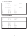
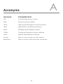
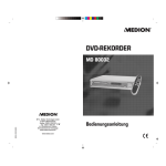
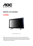
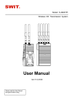
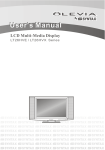
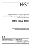
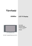
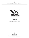
CWHDI-TX2 & RX2 Wireless Multi-Format input Transmitter to HDMI Receiver Box Operation Manual CWHDI-TX2 & RX2 Disclaimers The information in this manual has been carefully checked and is believed to be accurate. Cypress Technology assumes no responsibility for any infringements of patents or other rights of third parties which may result from its use. Cypress Technology assumes no responsibility for any inaccuracies that may be contained in this document. Cypress also makes no commitment to update or to keep current the information contained in this document. Cypress Technology reserves the right to make improvements to this document and/or product at any time and without notice. Copyright Notice No part of this document may be reproduced, transmitted, transcribed, stored in a retrieval system, or any of its part translated into any language or computer file, in any form or by any means - electronic, mechanical, magnetic, optical, chemical, manual, or otherwise - without express written permission and consent from Cypress Technology. © Copyright 2009 by Cypress Technology. All Rights Reserved. Version 1.0 November 2009 Trademark Acknowledgments All products or service names mentioned in this document may be trademarks of the companies with which they are associated. Safety Precautions Please read all instructions before attempting to unpack or install or operate this equipment, and before connecting the power supply. Please keep the following in mind as you unpack and install this equipment: Always follow basic safety precautions to reduce the risk of fire, electrical shock and injury to persons. To prevent fire or shock hazard, do not expose the unit to rain, moisture or install this product near water. Never spill liquid of any kind on or into this product. Never push an object of any kind into this product through module openings or empty slots, as you may damage parts. Do not attach the power supply cabling to building surfaces. Do not allow anything to rest on the power cabling or allow it to be abused by persons walking on it. To protect the equipment from overheating, do not block the slots and openings in the module housing that provide ventilation. Revision History Version No V1 Date 20091029 Summary of Change Preliminary Release Table of Contents 1. Introduction ……………………..……………………...…........….……. 1 2. Applications …………………..………………….……...................….. 1 3. Package Contents ………………………...........……….................… 1 4. System Requirements ……………..……….........………............……. 1 5. Features …………………………………………......……........…...…… 2 6. Specifications ………………………………...……..........………....…. 3 7. Operation Controls and Functions ……………...……..............…… 7.1 Transmitter ................................................................................... 5 7.1.1 Front Panel ……………………..……........…….......…...….… 5 7.1.2 Real Panel ............................................................................. 6 7.2 Receiver ...................................................................................... 7 7.2.1 Front Panel ………………......……………..……......…...….… 7 7.2.2 Real Panel ............................................................................. 8 IR Cable Pin Definitions .................................................................... 9 8.1 IR Blaster ....................................................................................... 9 9. Remote Control .......................…......……………..........…..…....…... 9 10. Connection and Installation ........................................................... 10 10.1 Unicast mode ............................................................................ 10 10.2 Broadcast mode ...................................................................... 10 10.3 Remote Control distance ........................................................ 11 Troubleshooting ……...……........……...........................................… 12 11.1 Input Signal Specifications ....................................................... 13 11.2 Output Signal Specifications ................................................... Acronyms …...................................................................................... 13 8. 11. 12. 5 14 1. Introduction The wireless HDMI transmitter and receiver boxes use baseband technology with Wireless High Definition Interface (WHDI) to deliver uncompressed HD audio and video. It can transmit within a distance of 20 meters while maintaining superb, wired equivalent quality and reliability with little to no lag. Both transmitter and receiver boxes come with built in antennas, making them a sleek addition to your Home or Office. These units can also convert analog and digital signals to HDMI V1.2 in order to be shown on displays. 2. Applications Multi format input to wireless HDMI output Integrate your home entertainment system Showroom Display 3. Package Contents Wireless multi-format input Transmitter box Wireless HDMI output Receiver box 1 x 5V/6A DC power supply adaptor for transmitter box 1 x 5V/2.6A DC power supply adaptor for receiver box User manual CR-77 Transmitter Remote IR blaster cable AC Power cable 2 x Holder 4. System Requirements Input source equipment(s) and output display device(s) with HDMI cables. 1 5. Features Uncompressed HD audio/video wireless transmission at wire-equivalent quality Supports most video resolutions including 480i/p, 576i/p, 720p, 1080i, VGA@60/72Hz, SVGA@56/60/72Hz, XGA@60/70Hz and 1080p@24/30fps Supports analog/digital video/audio input and HDMI output to display HDCP keysets allows each HDMI input to independently connect to an HDMI display Supports 3D comb filter and 3D noise reduction (DNR) Supports 3D noise reduction (DNR) Supports analog format conversion from 480i/576i to 480p/576p with a hot key on the transmitters front panel and remote control Operational within a distance of 20 meters, no direct line of sight required. Real time link, with a lag of less than 2 milliseconds. Strong 256-bit AEC based encryption for security Video Data Rates 1.5Gbps 5GHz licensed band, MIMO(Multiple Input Multiple Output) RF Supports CEC bypass and input switch functionality Fully HDCP Compliant Operational in either Unicast or Broadcast mode Auto shutdown when one of the devices is turned off Instant signal transmission with a timing change of less than 10 seconds. Control Channel allows two-way communications of 10Kbps Audio support PCM (2CH), DTS (5.1CH) & AC3 (5.1CH) 2 6. Specifications Radio Power Transmit power is configurable up to 63mW (+18dBm) Video Resolutions 480i/p, 576i/p, 720p, 1080i, VGA@60/72Hz, SVGA@56/60/72Hz, XGA@60/70Hz and 1080p@24/30fps Frequencies Supported 4.9 ~ 5.9GHz Modulation MIMO OFDM with WHDI video-modem technology Bandwidth 18MHz Wireless Range 20 meters open field Antenna Transmitter: 4 transmit antennas and 2 receive antenna Receiver: 5 receiver antenna and 1 transmit antenna Digital Video Interface Up to 24 bit RGB or YCbCr (4:4:4) System Latency Less than 1 millisecond delay between video/ audio source and sink Security Strong 256 bit AES-based encryption Application Bandwidth Control Channel allows two-way communications of 10Kbps Input ports 2 x Components with R/L 2 x Video and 2 x S-Video with R/L 2 x HDMI 1 x PC with R/L 1 x IR Blaster Output port 1 x HDMI Power Supply Transmitter: 5V/6A DC (US/EU standards, CE/FCC/UL certified) Receiver: 5V/2.6A DC (US/EU standards, CE/FCC/UL certified) ESD Protection Human body model: ± 10kV (air-gap discharge) ± 6kV (contact discharge) 3 Dimensions (mm) Transmitter: 226(W) x 165(D) x 46(H) Receiver: 226(W) x 165(D) x 46(H) Weight(g) Transmitter:500 Receiver:440 Chassis Material Plastic Silkscreen Color White Operating Temperature 0˚C ~ 40˚C / 32˚F ~ 104˚F Storage Temperature -20˚C ~ 60˚C / -4˚F ~ 140˚F Relative Humidity 20~90% RH (non-condensing) Power Consumption Transmitter: 13.5W Receiver: 7.6W 4 7. Operation Controls and Functions The following sections describe the hardware components of the unit with installation guide and setting methods. 7.1 Transmitter 7.1.1 Front Panel 480i480p 576i576p ② 2 1 COMP 2 1 S-VIDEO 2 1 VIDEO 2 1 HDMI PC LINK POWER ③ ④ ⑥ ① INPUTIP/5SEC ② INPUT+ ③ ⑤ ⑥ ID POWER ① IR sensor ② 480i → 480p / 576i → 576p LED indicator and INPUT I P/5SEC button: Press this button to select the input source from COMP1 to PC or press for 5 seconds to switch between interlace and progressive format, yellow LED light will turn on when switched from interlace to progressive format, when switching from progressive to interlace the light will not turn on. ③ Input source selection: Press the input button to switch to your desired input sources from PC to COMP1, green LED will illuminate according to your selection. ④ Link LED: When the system is in search mode the blue LED will flash repeatedly, and when it is in signal linking mode it will slowly flash. When the LED is on and there is no flashing it means the system is ready and audio or video can be sent. ⑤ ID: Press this button with the receivers “ID” button for two seconds to connect the systems. Before they left the factory the systems were already connected so there is no need for the user to reset the connection unless the systems cannot link up properly. Press the ID button for more than ten seconds to switch between Broadcast and Unicast mode. When the green LED is on it means the system is in Unicast mode and when the Red LED is lit the system is in Broadcast mode. The default mode for this system is Unicast and it is recommended to use this for home use. It is not necessary to press both the transmitter and receiver buttons at the same time. Note: Due to the nature of Broadcast mode, which has no uplink, there can be no communication between Transmitter and Receiver, the result is the following: • HDCP protected content should not be transmitted. • CEC and EDID repeater functions cannot be supported. • Broadcast mode is not HDCP compliant. • Only supports single transmitter link with multiple receivers. ⑥ Power: The LED will illuminate when power is on. 5 7.1.2 Rear Panel COMPONENT IN AUDIO 2 AUDIO 1 Y2 Y1 Pb/Cb 2 Pb/Cb 1 Pr/Cr 2 Pr/Cr 1 SVIDEO 2 SVIDEO 1 VIDEO 2 VIDEO 1 ① ② AUDIO 2 AUDIO 1 HDMI 1 ③ PC HDMI 2 IN ④ ① Component inputs: These slots are for connecting the component and R/L output ports of your source equipments such as DVD player or set-top-box with component video and R/L cables. Y1, Pb/Cb1,Pr/ Cr1, & Audio1 and Y2, Pb/Cb2, Pr/Cr, & Audio2 are two individual loops for source equipments. ② Video/S-Video inputs: These slots are for connecting the Video/S-Video and Audio (R/L) output ports of your source equipments such as DVD player or set-top- box with S-Video and RCA cables. The SVideo1, Video1, & Audio1 and SVideo2, Video2, & Audio2 are two individual loops for source equipments. ③ PC- in-AUDIO: These slots are for connecting the PC and or audio output port of your source equipment such as Notebook or PC with D-Sub15pin and R/L cables. ④ HDMI inputs 1/2: These slots are for connecting the HDMI or DVI output ports of your source equipments such as DVD player or set-top-box with HDMI cables. ⑤ Power: Plug the 5V DC power supply included in the package into this unit and connect the adaptor to an AC wall outlet. ⑥ IR Blaster: Connect the IR blaster cable included in the package and place it in front of the source equipments. The IR blaster will transmit the infrared signal to the connected source with the existing remote signal sent to this device. AUDIO POWER IR BLASTER ⑤ 5V 6A ⑥ 6 7.2 Receiver 7.2.1 Front Panel LINK POWER ① ② ③ ID POWER ④ ② ① Link LED: When the system is in search mode the LED will flash repeatedly and when the system is in signal linking mode it will slowly flash. When the LED is on and no longer flashing it means a connection has been established and audio/ video can then be sent. ② Power button: Press this button to power up the system, when the LED is lit the system has been turned on. ③ IR Sensor ④ ID: Press this button along with Transmitters “ID” button for two seconds to connect the systems. Before they left the factory the systems were already set up so there is no need for the user to reset the connection unless the systems cannot link up properly. Press the ID button for more than ten seconds to switch between Broadcast and Unicast mode. When the green LED is on it means the system is in Unicast mode and when the Red LED is lit the system is in Broadcast mode. The default mode for this system is Unicast and it is recommended to use this for home use. It is not necessary to press both the Transmitter and Receiver buttons at the same time. 7 7.2.2 Rear Panel ① HDMI output: This slot is to connect the HDMI cable to the HDMI input of your display. ② Power: Plug in the 5V DC power supply included in the package and connect the adaptor to an AC outlet. HDMI OUT ① RESERVED POWER ② 5V 2.6A 8 8. IR Cable Pin Definitions 8.1 IR Blaster ① Power 5V ② NC ③ IR blaster signal ① ②③ Note: The frequency on both IR Receiver & Blaster can support 36~387KHz with NEC code. 9. Remote Control ① PC: Press this button to select PC input. ② Format selection: Press this button to switch between Interlace and Progressive format. ③ Power: Press this button to turn on/standby the unit. ④ HDMI 1/2: Press no. 1 or 2 buttons to select HDMI 1 or 2 inputs. ⑤ Component 1/2: Press no. 1 or 2 buttons to select Component 1 or 2 inputs. ⑥ S-Video1/2: Press no. 1 or 2 buttons to select S-Video 1 or 2 inputs. ⑦ Video1/2: Press no. 1 or 2 buttons to select Video 1 or 2 inputs 9 ①② PC 480i480p 576i576p POWER ③ ④ ⑤ ⑥ ⑦ HDMI 1 2 COMP 1 2 SVIDEO 1 2 VIDEO 1 2 CR-77 10. Connection and Installation 10.1 Unicast mode PS3 HDMI HDMI HDMI HDMI HDMI Cable DVD LCD TV 20 Meters Blu-ray 10.2 Broadcast mode HDMI HDMI HDMI Cable LCD TV PS3 HDMI HDMI HDMI HDMI HDMI Cable DVD LCD TV 20 HDMI Cable HDMI HDMI rs e et M LCD TV HDMI Cable 10 HDMI HDMI Blu-ray LCD TV 10.3 Remote Control distance 3M 3M 30° PC 30° 480i480p 576i576p 3M 7M 3M 30° POWER PC HDMI 1 1 2 1 2 1 2 1 2 SVIDEO VIDEO 1 POWER 2 COMP SVIDEO 1 480i480p 576i576p HDMI 2 COMP 1 30° 2 VIDEO CR-77 2 CR-77 11 7M 11. Troubleshooting Issue Power LED does not light up when power is on. Recommendation 1. Check if the right adaptor is used. Transmitter: 5V/6A and Receiver: 5V/2.6A 2. Check that all power connectors are plugged in correctly. 3. Push the power buttons to turn on the devices. After powering on Tx & Rx boxes the links LED is flashing quickly/slowly without an image being displayed. 1. This is normal when the devices are in search or signal linking mode. Once a link has been established and the signal is reliable it will no longer flash. 2. If the LED has been flashing repeatedly for more than 3mins it is recommended to re-connect the devices by pressing the “ID” button for two seconds. 3. If the LED has been slowly flashing for more than 3mins make sure the input cable of the transmitter is properly connected. The link LED is turned on and consistent, but without an image displayed or an unexpected image. 1. Check if the source is compatible with the device. The device supports up to 1080i, so please be sure that the source is sending a compatible signal for the display and the display can also accept that signal. 2. Check if both source and the display are HDCP/ CEC complaint. 3. Check if TV is in HDMI mode. 4. Check if both source and display are connected stably. Input LED does not turn on. 1. When linking for the first time, if the output display is not properly connected, the red LED will not turn on; therefore check if the HDMI output is connected. Different color on Power LED. 1. Red Power LED means system is in Broadcast mode and Green Power LED means Unicast mode. If Tx has green LED but Rx has red LED, press Rx’s ID button for ten seconds. But when Broadcast mode is demanded press Tx’s ID for ten seconds to switch to Broadcast mode. 12 11.1 Input Signal Specifications PC Resolution Vert Rate VGA 640x480 60/72Hz SVGA 800x600 56/60/72Hz XGA 1024x768 60/70Hz HDTV Resolutions Vert Rate 480p 720x480 60Hz 480i 720x480 60Hz 576p 720x576 50Hz 576i 720x576 50Hz 720p 1280x720 50, 60Hz 1080i 1920x1080 50, 60Hz 1080p 1920x1080 24, 30fps 11.2 Output Signal Specifications PC Resolution Vert Rate VGA 640x480 60/72Hz SVGA 800x600 56/60/72Hz XGA 1024x768 60/70Hz HDTV Resolutions Ve rt Rate 480p 720x480 60Hz 480i 720x480 60Hz 576p 720x576 50Hz 576i 720x576 50Hz 720p 1280x720 50, 60Hz 1080i 1920x1080 50, 60Hz 1080p 1920x1080 24, 30fps Note: Output resolution limit on the TV/Monitor's specifications. 13 A Acronyms Acronym Complete Term CEC Consumer Electronics Control DNR 3D noise reduction (DNR) HDCP High-bandwidth Digital Content Protection HDMI High-Definition Multimedia Interface MIMO Multiple Input Multiple Output OFDM Orthogonal Frequency Divison Multiplex WHDI Wireless High Definition Interface Unicast Able to connect with one other device. Broadcast Able to connect with more than one device. 14 CYPRESS TECHNOLOGY CO., LTD. Home page: http://www.cypress.com.tw 20091116 MPM-CWHDITX2RX2