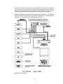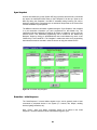
1
Niles Audio Corporation
IntelliControl Reference Manual
Version 8.0 July 2000
Contents
1A. IntelliControl Features and Benefits ................................................................................................................... 1
A Complete System...................................................................................................................................................... 1
One Touch “Intelligent Macros” To Turn The Entire Home Theater On or Off .................................................... 2
Automatically Unmute the System.............................................................................................................................. 2
Manage and Automate “Unfriendly” Components .................................................................................................. 2
Trigger Screens, Screen Masking Devices, Projector Lifts, Curtains and Drapes.................................................. 2
PC Programmable with IntelliFile II......................................................................................................................... 2
Proudly Made in USA................................................................................................................................................. 3
1B. IntelliControl Parts Guide..................................................................................................................................... 3
The Tabletop Remote .................................................................................................................................................. 3
The Main System Unit (MSU) .................................................................................................................................... 4
1C. Selling the System................................................................................................................................................... 6
Selling Automated Home Theater Systems ................................................................................................................ 6
Solving The Problems of Conventional Home Theater Operation........................................................................... 6
Problem One: Turning the System On .................................................................................................................. 6
The IntelliControl Solution: Syncronization (Sync) ............................................................................................. 6
Problem Two: Selecting Inputs & Modes ............................................................................................................. 8
The IntelliControl Solution: Software Managers to Select Inputs and Modes .................................................... 8
1D. Comparison of Home Theater Control Systems..............................................................................................10
2A. Power Syncronization..........................................................................................................................................11
Infrared Turn On/Off Requires “Sync” ...................................................................................................................11
Components that Don’t Need Sync – Those with Latching Power.........................................................................11
Remember the Exception – Tuners built into Receivers and Televisions...............................................................12
2B. Sync Methods and Options .................................................................................................................................12
Video Sync .................................................................................................................................................................12
Syncing the TV.....................................................................................................................................................13
12 Volt Sync...............................................................................................................................................................13
1. 12V DC Sync via a Wall Adapter Plugged into a Switched AC Outlet ......................................................13
2. Niles LS-1 Light Sensor ................................................................................................................................14
3. Niles OTI-512 Voltage Sensor.......................................................................................................................14
4. Niles APC-2 Current Sensing Switcher ........................................................................................................14
5. Niles IPC-6 Current Sensing AC Power Controller .....................................................................................14
Each Sync Connection on the Main System Unit Corresponds to a Particular Master Key on the Tabletop
Remote .......................................................................................................................................................................15
Conventional Labeling Rule: Video on the Left, Everything Else on the Right .....................................................15
Once Again: Remember the Exception...............................................................................................................16
i
2C. Component Compatibility ..................................................................................................................................16
Infrared Compatibility ..............................................................................................................................................16
Testing Components for Automation Conflicts........................................................................................................17
Testing Components for Sync Method .....................................................................................................................17
Sync Off Delay .....................................................................................................................................................18
3A. Pages, Keys, and Sequences................................................................................................................................21
An Address For Every IR Command........................................................................................................................22
Issue A Sequence From A Function Key..................................................................................................................22
Purpose of the Master Key Pages ............................................................................................................................23
Purpose of the Default Page.....................................................................................................................................23
Purpose of the Library Pages...................................................................................................................................24
3B. Function Key Memory Limitations ...................................................................................................................24
3C. Master Key Automation: Part 1 - One Touch System Turn On...................................................................25
Sync Snapshot............................................................................................................................................................26
Event One – Initial Sequence....................................................................................................................................26
Event Two - TV Power..............................................................................................................................................27
Event Three - Preamp Power ...................................................................................................................................27
Event Four - Component Power (Not Applicable to Master Keys Nine and Ten).................................................27
Event Five - TV Input................................................................................................................................................27
Event Six - Preamp Input..........................................................................................................................................27
Event Seven - Surround Mode..................................................................................................................................27
Event Eight - Ending Sequence ................................................................................................................................27
3E. Master Keys: Part 2 - Special Features............................................................................................................28
Automation Bypass for Manually Adjusted Features..............................................................................................28
Automation Bypass for a Typical Application....................................................................................................28
How to Program “Component Power” for Multiple Master Keys which Share a Common Source..................29
Press and Hold a Master Key...................................................................................................................................30
Custom Programming for Preamp/Receivers with Separate On/Off Commands .................................................30
3F. Master Keys: Part 3 - Direct IR, Sequence IR, and Managers......................................................................31
Direct IR - A Different “Single” IR Code for each of the Component’s Inputs.....................................................31
Testing Direct IR ..................................................................................................................................................31
Sequence IR— a Single “Input Toggle” Command and a Secret Back-Door “Anchor” Command(s) ..............31
Finding the Secret Back-Door “Anchor” Command..........................................................................................31
Testing the “Anchor” Command .........................................................................................................................31
Input Manager – For Components with only a Single “Input Toggle” Command...............................................32
ii
Testing the “Input Manager” Method..................................................................................................................32
Determine the “Defaults” .....................................................................................................................................32
3G. Master Keys: Part 4 – Intelligent System Turn Off........................................................................................32
Event 1 - “System Off” Initial Sequence..................................................................................................................32
Event 2 - TV Auto Turn Off.......................................................................................................................................33
Event 3 - Auto Volume Reset ....................................................................................................................................33
Event 4 - Preamp Auto Turn Off ..............................................................................................................................33
Event 5 - Component Auto Turn Off ........................................................................................................................33
Event 6 - “System Off” Ending Sequence................................................................................................................33
3H. The Audio, Video, and Assignable Relays with Control Voltage Output....................................................33
Relay Voltage Limitations.........................................................................................................................................33
Audio 12V Output .....................................................................................................................................................34
Video 12V Output and Relay....................................................................................................................................34
Assignable 12V Output and Relay............................................................................................................................34
3I. Utilities.....................................................................................................................................................................34
ID Code .....................................................................................................................................................................34
Volume Reset.............................................................................................................................................................35
IR Routing..................................................................................................................................................................35
Dual TV .....................................................................................................................................................................35
Mute Manager...........................................................................................................................................................36
Memory Usage..........................................................................................................................................................36
4A. Using Your Original Remote Controls via an IR Repeater System .............................................................37
Integrating a Second Zone........................................................................................................................................37
Turning On Common Sources in Multi-Zone Systems............................................................................................38
Integrating the Niles RVL-6 and MRZ-6 Multi-Room Controllers.........................................................................39
Multiple TV Array In A Media Room.......................................................................................................................39
Integrating the Niles IntelliPad™ Into the Home Theater......................................................................................39
Integrating a Learning Touchscreen Into An IntelliControl Home Theater..........................................................39
Teach the RF/IR Conversion Codes for the Master Keys, Function Keys, and System Off Key...........................40
Step-by-Step Installation of a New System..............................................................................................................41
1.
Connect, Power Up, and Test The Home Theater..........................................................................................41
2. Check MSU Location for Freedom from Interference....................................................................................41
3. Connect and Power Up the MSU, Your PC, and the IntelliFile II ..................................................................41
5. Testing and Troubleshooting RF Transmission and Reception.......................................................................42
iii
6. Connect Flashers and Sync Cables...................................................................................................................43
7. Flasher Level Check ..........................................................................................................................................44
8.
The IR/RF Test LED.........................................................................................................................................45
Specifications................................................................................................................................................................46
The IntelliControl Tabletop Remote.........................................................................................................................46
The IntelliControl Main System Unit .......................................................................................................................46
iv
Chapter
1
IntelliControl® Home Theater Automation
System
1A. IntelliControl Features and Benefits
Introducing the IntelliControl, the world’s first affordable home theater automation system
expressly designed to provide true one-touch operation. Unlike universal remote controls,
the IntelliControl System senses the actual on/off state of all of your audio/video
components. When you press a Master Key, the built-in microprocessor has the
intelligence to decide which components need to be powered up, depending on what
Master Key was selected and the On/Off state of the components.
After the system components have been turned on, the IntelliControl issues all of the
necessary surround-sound mode commands, the preamp input selection commands, the
TV input commands, and any “play” or “favorite station” commands. For the first time,
most anyone in the family can operate the system without training, prompting or headscratching.
Ten Master Keys can be custom labeled to reflect your system components or features.
When you select a source, it lights up letting you know it’s ready to be controlled.
Traditional universal remotes are confusing because “aux” might actually select the
satellite receiver, and “VCR2” selects the TV. Now, each of the sources in your system
are correctly labeled. By pressing one of these Master “scene-setting” Keys, your system
is completely turned on, configured, and set up to watch and control the selected source.
The only other systems capable of this unique combination of custom labeling and full
automation of a mixture of multi-brand components are very expensive touchscreen
automation systems. In addition to the expense, touchscreens are menu-driven, and
always require more than one step to operate. The IntelliControl offers genuine onetouch operation at an affordable price.
A Complete System
The system consists of an ergonomically designed RF (radio frequency) Tabletop Remote
Control and an “intelligent” Main System Unit (MSU). Powerful combinations of hardware
and software functions within the Main System Unit manage and control every aspect of
the home theater.
1
One Touch “Intelligent Macros” To Turn The Entire Home Theater On or Off
Normal home theater system operation requires you to turn on multiple components. It is
easy to make a mistake, which can create a situation where you must be a detective and
hunt down the fugitive component that is “off”, when it really should be “on”. The
IntelliControl eliminates all of this troubleshooting. A single touch of any of the ten installer
labeled “scene-setting” keys (typically labeled for sources e.g. TV, VCR, CD) will initiate
an intelligent sequence of commands (macro).
The IntelliControl will only issue a component’s power command if it is off. All of the
necessary components are turned on, every time. After the system components have
been turned on, the IntelliControl automatically completes the system configuration,
enabling you to watch and listen to the selected source. Now, a complex mix of different
brands of audio/video components can be operated with the same ease and simplicity of a
traditional television set.
Automatically Unmute the System
Many surround-sound preamps or receivers can unpleasantly surprise you with their
“mute” functions. For example, if you mute the system to answer a phone call and then
press a Master Key or the “Volume Up” Key, the volume will be too low. If you first raise
the volume then remember that you muted it, a press of the “Mute” button will issue a
deafening blast.
The IntelliControl is capable of “managing” the mute command. The system will mute
when you press the “Mute” key. However, it will now unmute automatically whenever you
press a Master Key, “Volume Up” or the “Mute” key.
Manage and Automate “Unfriendly” Components
Many high-performance audio/video components have remote control functions that are
impossible to automate with conventional automation equipment. The components are
really just designed for the user who demands manual control at all times. The
IntelliControl has unique software “managers” which enable complete automation of
components that are difficult to automate. For the first time, components chosen for
optimum performance can be automated using the IntelliControl.
Trigger Screens, Screen Masking Devices, Projector Lifts, Curtains and Drapes
The IntelliControl provides dedicated 12-volt DC triggers for both the Video and the Audio
Scenes. The Video scene also triggers a latching (normally open) and a latching (normally
closed) contact relay. An "assignable" relay and 12v DC voltage can be triggered by any
key as a step in a programmed sequence. These relays and voltages enable devices
which are not IR controlled to be automated by the IntelliControl system.
PC Programmable with IntelliFile II
An IntelliControl system configuration can be programmed, saved, and edited using the
Niles IntelliFile II PC Interface and Programming Software. A PC running Windows 95 or
98 is required. Unfortunately, Niles does not offer a Mac compatible version at this time.
2
Proudly Made in USA
The IntelliControl is designed and built in the USA and comes with a limited two year parts
and labor warranty.
1B. IntelliControl Parts Guide
Figure 1 The IntelliControl Tabletop Remote
The Tabletop Remote
The Tabletop Remote is a radio frequency (RF) transmitter which communicates with the
Main System Unit (MSU) on a RF carrier frequency of 418MHz. The Tabletop Remote
features the following:
•
Ten Master Keys – The ten Master Keys on the left side of the remote may be
custom labeled and will initiate the IntelliControl’s automation functions when
programmed via the IntelliFile II PC Interface and Programming Software. Pressing a
Master Key will prompt the MSU to check the On/Off status of all of the components in
the system and issue the necessary IR commands to configure the system so the
user may enjoy the selected source.
•
System Off Key – When pressed, the Tabletop Remote will instruct the MSU to
check the On/Off status of all the components in the system and issue the necessary
IR commands to power down the system.
3
•
Backlight Key – Pressing the Backlight Key (located on the upper left corner of the
Tabletop Remote) will illuminate all the keys to enable complete control of the system
in dark rooms.
•
Function Keys – The thirty-two Function Keys include the numeric, menu, transport,
mute, volume, and channel keys. Once a Master Key is selected, the Function Keys
correspond to the functions of that selected source. However, the volume and mute
keys are usually programmed to control the preamp only.
Figure 2 Main System Unit – Top View
Figure 3 Main System Unit – Front View
The Main System Unit (MSU)
The Main System Unit is the “brain” of the IntelliControl system. Once a RF command is
issued from the Tabletop Remote, the MSU processes the command and controls all
functions of the system. All programming is stored inside the MSU. The Main System Unit
features the following:
•
Power Connector – Located on the upper left side of the MSU, the Power Connector
accommodates a 12V DC 800mA UL approved external power supply (FG00667 included).
4
•
RF Test Port – Also located on the upper left side of the MSU is the RF Test Port.
The RF Test Port enables you to receive real-time confirmation that RF signals are
received and understood, detect interference, and test for sync status. The bicolor
RF/IR Test LED (FG00727) is available as an accessory, and should be sold and
installed in every IntelliControl home theater.
•
Video Sync Inputs – The eight Composite (RCA) Video Sync Ports are provided to
sense the on/off power status of IR controlled components with video output. Your
system design may require additional video cables and “Y” adapters.
•
12V Sync Inputs – The 12V Sync Inputs are provided to sense the on/off power
status of IR controlled components. Your system design may require 12V DC wall
adapters or Niles switchers (APC-2, LS-1, OTI-512) with a 10’ Accessory Cable
(FG00724).
•
Transfer Connector – The three conductor Transfer Connector enables the transfer
of programming information from the IntelliFile II PC Interface or the original
IntelliControl Programmer to the MSU and vice versa. You may want to permanently
install a 20’ Transfer Cable (FG00725) to provide future access for programming
updates.
•
IR Flasher Outputs- The twelve IR Flasher Outputs issue IR codes to IR controlled
components. Your system design may require IRC-2P MiniFlashers (FG00726)
and/or 3.5 to 3.5 mono mini-plug cables for hardwired connections to compatible
components.
•
12V DC Control Voltage Outputs – These connections can be used to trigger
screens, Niles switchers, and other devices. Your system design may require 10’
Accessory Cables (FG00724). The IntelliControl features an “Audio 12V” output
(active whenever a source that utilizes the preamp is selected), a “Video 12V” output
(active whenever a source that utilizes the TV is selected), and an “Assignable 12V”
output (activated as part of a sequence with the “Assignable Relay On” command).
•
Dry Contact Closures / Relays – These connections can be used to trigger lights,
curtains, screens, lifts, and other devices. Your system design may require multiconductor cable. The IntelliControl features a “Video Relay” (active whenever a
source that utilizes the TV is selected), and an “Assignable Relay” (activated as part of
a sequence with the “Assignable Relay On” command).
•
IR Data Input Connectors (“Home Theater IR” and “Second Zone IR”) – These
connections enable IR data to be fed into the MSU from Niles IR sensors, keypads, IR
Main System Units, or Multi-room Controllers around the house. IR data received at
the “Home Theater IR” port is passed through all flashers. IR data received at the
“Second Zone IR” port is passed through flashers 1 – 8 only.
•
Antenna Socket – This F-connector accommodates a 1’ to 200’ length of high quality
quad-shielded RG-6 coax cable with 6-3/4” of the center conductor exposed. It is
suggested that the exposed tip of the antenna be located as far from the main
equipment location (and as close to the user’s location) as practical.
•
IR Flasher Level Controls – The twelve flasher level controls enable the installer to
control the strength of the IR output sent to each of the components in the system.
Flasher strength increases as the pots are turned clockwise (a jeweler’s screwdriver is
5
required). Before beginning to program the system, it is recommended that a Niles IR
Sensor be connected to the MSU’s “Home Theater IR” port and each of the flasher
level adjustments be set using the components’ original remote controls.
1C. Selling the System
Selling Automated Home Theater Systems
In the past, selling a home theater system has always involved system design trade-offs.
With every profitable upgrade you sell to your customer there is a “hidden” cost to you
after the installation, which is your time.
Along with selling and installing the system, you must assume the responsibility for training
the customer to actually use the new features or enjoy the enhanced performance. The
frustration many consumers feel, even after repeated training sessions, certainly limits
referrals and sometimes leads to refunds. In any event, the time required to drill customers
so that they can reliably turn on and operate the system can be ridiculously expensive for
you and tedious for your customer. The IntelliControl enables you, the salesperson, to
design and sell absolutely automated home theater systems (systems that require minimal
training to operate and which generate repeated referrals).
In order to successfully sell the IntelliControl to consumers, you should be able to
effectively present what “Home Theater Automation” means, in terms the consumer will
understand. The following sections elaborate how the IntelliControl’s automation differs
from anything that has ever been sold and installed into a home theater at this price point.
Solving The Problems of Conventional Home Theater Operation
The IntelliControl uses a unique approach to solve the classic problems of operating a
home theater. In this section, we will take a closer look at what those problems are, and
how the IntelliControl solves them.
Problem One: Turning the System On
In a conventional system, turning on a home theater with a remote control can be so
difficult, that most people simply walk up to the equipment where they can see each
component and try to remember what needs to be done. Since most components feature
“toggle” power commands (one button which turns the component both “On” and “Off”),
you cannot simply press the power button on each of your remotes in turn or issue a
macro of many power commands from a sequencing remote or touchscreen. For
example: If you put the videotape into your VCR, it would automatically turn on, and the
act of pressing the power button on each of your remotes (or pressing the macro button on
your touchscreen) would turn on the rest of your system, but would turn off the VCR).
The IntelliControl Solution: Syncronization (Sync)
The IntelliControl’s Main System Unit is connected to all of the home theater components.
Its unique video and 12V sensing circuits enable it to actually “know” whether each
component is on or off.
6
When the user presses any Master Key, the IntelliControl’s microprocessor checks the
power status of each component and synchronizes the system to the end user’s desires
by issuing only the necessary power commands. No matter what their previous on or off
states, the IntelliControl will know exactly which components need to be powered up.
Power synchronization is not just used when the system is first turned on. It is also used
when a new Master Key is selected. The IntelliControl checks to see if anything needs to
be turned on or off, and issues the necessary power commands.
Figure 4 System Schematic
7
Problem Two: Selecting Inputs & Modes
Home theaters need to have the surround receiver’s audio inputs selected, the correct
surround-sound mode selected, and the correct TV input selected. Even if there is a
separate button for every mode or input, the user must remember which input label is
correct for each component and keep track of which remote is which. Although some
remotes have the ability to issue “macros”, most systems incorporate at least one
component that is “macro-proof” (a component that uses a single “INPUT” or “MODE”
command to cycle through all of the choices). There is no way for the remote control to
“know” which input was last selected. So, the consumer must remember which input it was
and cycle through the choices manually. Operation is frustratingly complex for anyone.
The IntelliControl Solution: Software Managers to Select Inputs and Modes
The IntelliControl’s Main System Unit is programmed with powerful software “managers”
that automate Input and Mode selection. No matter what type of IR command is required
to change the inputs or the modes, The IntelliControl automatically selects the correct
configuration for the source selected.
Additionally, for the first time, you can design sophisticated configurations that improve
system performance without worrying about the difficulty the end-user might have
remembering everything (i.e. you could run S-Video direct to the TV’s S-Video input for the
DSS, while composite video is run from the other sources to the TV’s video input).
This automation does not get in the way of hobbyists who like to play with the surroundsound modes. The IntelliControl will automatically select the normal surround-sound
mode for each input when the user presses a Master Key.
However, if the hobbyist decides to experiment with different modes, he/she can press
one of the ten custom labeled Master Keys (labeled “Surround” for example), change and
adjust the surround-sound, and when they return to the last source selected, the surroundsound mode will not automatically change back to the normal mode (this is an example of
the IntelliControl’s “Automation Bypass” feature). Only when the user selects a new source
will the IntelliControl take over again and automatically select the default surround-sound
mode for the new source. Now, the hobbyist can peacefully coexist with the rest of the
family, because he/she will never accidentally leave the system in the wrong input or the
wrong surround-sound mode.
Problem Three: Decorating Electronically – Putting All The Components In
Plain Sight
If the equipment is placed out of sight behind cabinet doors and an infrared repeater
system is installed, the user cannot see which component is on, which input is selected,
etc. Either way, the user is cursed with either a stack of components with cryptically
flickering LEDs in plain sight or a cabinet full of components that can only be operated if
the doors are open.
The IntelliControl Solution: Automation Allows Behind Closed Door
Operation
Because the IntelliControl automates all of the system’s functions, the user doesn’t need
to check the power status or the currently selected input of each component. The
IntelliControl is constantly checking the power status and the software Managers are
8
correctly configuring the system for any source. As a result, the components can be
placed behind closed doors.
Problem Four: When The System Turns On, The Volume Is Too Low, or Too
High
Surround-sound preamps/receivers typically stay at the last volume selected when they
are turned off. As a result, turning on a system can sometimes be puzzling because there
is no sound, while at other times, turning on a system can be ear-shattering.
IntelliControl Solution: The Volume Resets Automatically At Turn Off
The IntelliControl can be programmed to automatically reset the receiver’s volume to a
comfortable level. When the “System Off” key is pressed, the IntelliControl can be
programmed to issue the “Volume Down” for as long as necessary to take the
preamp/receiver to minimum, then raise it to a comfortable level regardless of how loud or
soft the system had been playing. Only then does the IntelliControl turn the system off.
The system always turns on at a moderate volume setting. No more puzzling or surprising
accidents.
Problem Five: The Pitfalls of Mute
It has been traditional for most surround-sound receivers and preamps to offer the end
user a separate “Mute” button. This button has created thousands of service calls
worldwide. You press “Mute” once, the system mutes, you press it again and it unmutes.
However, the user must remember that the system is muted. If the user forgets, then there
is no sound. Or worse, a service call is created.
IntelliControl Solution: Software Managers to Manage Mute
The IntelliControl’s Main System Unit can be programmed to automate the “Mute”
command. Now, when one person presses “Mute”, nobody has to remember anything.
The IntelliControl remembers. When anyone touches any key, the preamp will unmute.
Problem Six: Infrared Remote Controls Are Line-Of-Sight Only
In a conventional system using a “macro” remote, various problems can occur if the
remote control is not pointed correctly, or not held steadily in one position until all of its
commands are issued. If the user’s hand slips, or someone walks by, some of the
commands may not be received. Annoying problems, which are exaggerated in larger
rooms, will occur.
IntelliControl Solution: Radio Frequency Commands Between the Tabletop
Remote Control and the System
The IntelliControl issues a single RF “automation” command when a button is pushed.
Because radio signals operate at any angle and cannot be physically blocked, the
system’s automation is extremely reliable. All macros are issued by the MSU, which feeds
IR commands directly to the components. The IntelliControl provides the end-user with
one-touch operation every time.
9
1D. Comparison of Home Theater Control Systems
Figure 8 System Comparison
10
Chapter
2
Power Syncronization and Component
Compatibility
2A. Power Syncronization
Infrared Turn On/Off Requires “Sync”
Every component which requires an infrared command to turn “On” or “Off” must be
synced to the IntelliControl. Based on the “sync status” of the selected component, the
IntelliControl will know whether or not to issue a “Power” or “On” command when a Master
Key is selected. The same basic procedure applies to turning the system off. The
IntelliControl monitors the on/off status of the components in either of two ways, “12V
Sync” and “Video Sync”.
Components that Don’t Need Sync – Those with Latching Power
Components which “latch” into an “On” state when power is supplied do not need sync.
The term “Latching Power” describes any component which has a Power button which
“latches” into the “On” position and can be turned on automatically when AC power is
supplied. “Single” and “5-disc” CD players, as well as most Tape Decks traditionally plug
into the switched outlet of the preamp/receiver and do not require IR “power” or “On” and
“Off” commands to manage their power. Check the power consumption of each devices in
the system and total them. If all of the connected component’s combined power
consumption exceeds the limitations of the preamp’s switched outlet, you must specify a
Niles AC-6+ to switch the “On” and “Off”. See Figure 9
Figure 6 Using the Niles AC-3 (or AC-6+) to switch on source components featuring
“latching” power via the Audio Control Voltage Output. (The Audio 12V is automatically
activated whenever a source that utilizes the preamp is selected).
11
For some components, it may be useful to turn them on and off with a Niles AC-6+
triggered by one of the three relay voltages (“Audio”, Video”, or “Assignable”). You could
elect to turn on and off a latching power CD player via the Assignable Relay if you
specified an AC-6+ to power it on and off. When programming, you could add the “Relay
On” command to the CD Master Key’s Ending Sequence and the “Relay Off” command to
all other Master Keys and the “System Off” Key.
Figure 7 A projector with latching power may be turned on via an AC-6+ triggered by the
Video Control Voltage Output. (The Video 12V Output is automatically activated
whenever a source that utilizes the TV is selected).
Remember the Exception – Tuners built into Receivers and Televisions
It is important to note that a stereo receiver has both a tuner and a preamp in one chassis.
If the receiver does not feature separate “On” and “Off” commands (or latching power, in
which case it could be activated via the “Audio 12V” trigger and an AC-6+ as described
above), it must be synced to the “Preamp 12V” sync port.
Since the receiver’s AM/FM tuner is automatically turned on/off with the receiver, the tuner
itself does not need sync (or to have a “Component Power” command programmed on the
tuner’s page under “Components” when programming with IntelliFile II). Essentially, the
tuner is treated as a component with latching power. Likewise, most televisions have both
a television tuner and a television monitor in one chassis. You sync the television monitor
to the TV’s dedicated sync port, and treat the television tuner as a source with latching
power.
2B. Sync Methods and Options
The following are the methods you will use to signal the IntelliControl that a component is
on or off.
Video Sync
Most video sources provide either a picture or a blue-screen when the device is on. Using
a Y-splitter, this video output can be routed to both the video switching Preamp (or TV)
12
and to the MSU’s composite video sync port which corresponds to that source’s Master
Key.
Note: The labeling of the Master Keys on the Tabletop Remote must match the sync
connections on the MSU. (For example, if the VCR is Master Key #4, one side of the
VCR’s split video output must be connected to video sync port #4).
The IntelliControl’s video sync ports have an input impedance of 10,000 ohms. This high
impedance circuit assures that even with the use of a “Y” or splitter connection, the signal
sent to the television (or Preamp) is absolutely unaffected. Typically, a “Y” connector and
an additional video cable are needed for video sync. If the component has more than one
video output, only a cable is needed.
Syncing the TV
Televisions which have multiple inputs present a sync problem. Some TV’s do not output
a video signal from the Monitor Video output when there is no signal coming into the
selected input. Thus, the IntelliControl will be deceived into thinking that the TV is off, when
it is on. Although a TV’s monitor output will not provide reliable sync, there are four
options:
1. Use the TV’s “Tuner Output” if available. This will ensure that the Sync is reliable.
2. Specify a Niles APC-2 current sensing device to detect the flow of current to the TV
when it is on. Note: This is the only reliable way to sync a Plasma TV (assuming it
does not feature separate “On” and “Off” codes).
3. Use a Niles LS-1 Light Sensor. (See “12V Sync” options below)
4.
Use a TV with separate “On” and “Off” commands.
Note: The TV’s sync signal output (video or 12V) must be connected to the dedicated “TV
Sync” port on the IntelliControl MSU.
12 Volt Sync
The IntelliControl Main System Unit has 12V Sync connections for the system’s
preamp/receiver, TV Monitor (or projector), and up to eight source components. The 12V
Sync signal lets the IntelliControl know whether the component is on or off and can be
supplied by five different methods:
1. 12V DC Sync via a Wall Adapter Plugged into a Switched AC Outlet
Many preamps, integrated amps, receivers, surround-sound processors, and cable TV
descramblers have a switched AC outlet (i.e. the outlet is hot when the preamp is “on”,
and dead when the preamp is “off”) to automatically power up components with latching
power. In an IntelliControl system, the switched outlet may be expanded with an extension
cord or power strip to accommodate a 12V DC 200mA wall adapter and any “latching
power” components you may be using. The output of the wall adapter is connected to the
IntelliControl’s dedicated “Preamp 12V” sync input.
13
2. Niles LS-1 Light Sensor
The Niles LS-1 Light Sensor was designed to detect a change in brightness on a
component’s front panel display. When it senses a change in brightness, the LS-1 outputs
a constant 12V DC 500mA control voltage. A blocking cover is provided to prevent
ambient light from falsely triggering the LS-1.
Note: You may choose to sync direct-view or rear-projection televisions with the LS-1 Light
Sensor. In this sync application, the LS-1’s sensor is attached to the rear of the TV using
the blocking cover (or better yet – to the flyback transformer inside the TV. The Flyback
transformer resembles a automobile alternator and is located near the TV’s main power
supply and AC power cord connection). The LS-1’s sensitivity is adjusted to output a 12v
DC sync signal only when the TV is on.
Additionally, when syncing multi-disc CD changers or other digital components, it may be
possible to install the LS-1’s sensor inside the component’s optical digital output jack to
detect the presence of light coming from that port when the unit is powered on. The unit
must not emit any light from this port when the unit is in standby!
3. Niles OTI-512 Voltage Sensor
The Niles OTI-512 Voltage Sensor senses any control voltage between 3 and 30 volts AC
or DC, and outputs a 12V DC 500mA control voltage. The 12V DC output is connected to
the IntelliControl’s sync input dedicated to that component.
An accessory cable (the Niles FOS-512) will connect a Fosgate, Lexicon, Citation, or
Synthesis preamp to the OTI-512.
4. Niles APC-2 Current Sensing Switcher
The Niles APC-2 Current Sensing Switcher senses any change in power consumption
that is greater than 30 watts. When it senses that the power consumption has increased
(by the component turning on), it outputs a 12V DC 300 mA control voltage. In an
IntelliControl system, the component’s AC power plug is plugged into the unswitched
“Sensing” socket on the APC-2. The 12V DC output is connected to the IntelliControl’s
sync input dedicated to that component.
The APC-2 has several other features. For more info, please look up the APC-2 on our
website: www.nilesaudio.com
5. Niles IPC-6 Current Sensing AC Power Controller
The Niles IPC-6 Current Sensing Switch senses any change in a component’s power
consumption that is greater than 3 watts. When it senses that the power consumption has
increased, it outputs a 12V DC 300mA control voltage. In an IntelliControl system, the
component’s AC power plug is connected to the unswitched “Trigger” socket on the IPC-6.
The 12V DC output is connected to the IntelliControl’s sync input dedicated to that
component.
The IPC-6 is not an iPower surge suppression device, but it does have several other
useful features. For more info, please look up the IPC-6 on our website:
www.nilesaudio.com
14
Each Sync Connection on the Main System Unit Corresponds to a Particular
Master Key on the Tabletop Remote
The labels typically represent the sources of a system. Master Keys 1 through 7 feature
both “12V” and “Video” sync capabilities, Master Key 8 features only “12V” sync, but
Master Keys 9 and 10 have no sync connections at all. For each component, you must
utilize a Master Key which has the necessary sync capabilities. The preamp/receiver and
the television monitor do not need a Master Key assigned to them (but you may choose to
assign Master Keys to the receiver’s AM/FM tuner and the TV’s internal tuner). The TV
monitor and Preamp are system components that are needed to listen to and watch a
component. Therefore, they have been permanently assigned their own sync connections.
PRE - The surround-sound preamp/receiver for the system is assigned the “PRE 12V”
sync connector.
TV - The Television Monitor for the system is assigned to either the “TV 12V” or the “TV”
Video Sync connector. Note: The “TV” Video Sync connection method is reliable only if the
TV you are using has a “Tuner” output. Using the TV’s “Monitor” or “Video” output is not
reliable.
MASTER KEYS ONE through SEVEN - These Master Keys are assigned both “12V” and
“Video” sync connections.
LABEL EIGHT - This Master Key is assigned a “12V” sync connection only.
LABEL NINE and TEN - These Master Keys do not feature any sync connections at all.
However, these keys may be used as Master Keys if their components have “latching
power” or separate “On” and “Off” commands.
Figure 8 Master Key Sync Features
Conventional Labeling Rule: Video on the Left, Everything Else on the Right
Since most video components require sync, it is conventional to use the left hand column
for video sources, and utilize the right hand column for the rest of the system. Typically,
audio sources, sources with built-in or latching power, components which are always on
(i.e., lighting controllers), and manually controlled features are usually configured to master
Keys on the right side of the Tabletop Remote.
15
Once Again: Remember the Exception
Since the IntelliControl will be programmed to turn on the TV Monitor whenever a video
Master Key is pressed, there are a special set of sync connectors dedicated to the TV and
are unrelated to any of the other Master Keys. Likewise, the Preamp/Receiver has its own
Preamp sync and flasher connections unrelated to any of the other Master Keys.
If the television’s built-in tuner is a source for the system or if the receiver’s built-in AM/FM
tuner is a source, Master Keys do need to be assigned. However, even though the TV and
the Preamp need sync, the Master Keys for their internal tuners do not need sync
(because they represent the components which are built into the TV and the Preamp). The
IntelliControl will automatically check the sync of the Preamp when the “AM/FM” Master
Key is pressed, so it is not necessary to check the sync for the receiver’s tuner as well.
Because of this, you may assign the labels “TV” and “AM/FM” to any of the ten Master
Keys (including Master Keys 9 and 10), since sync for those sources is not necessary.
2C. Component Compatibility
Infrared Compatibility
All audio/video components in the system must be remote-controlled by infrared (IR). The
system was designed to be compatible with virtually any brand of equipment that transmits
IR commands on carrier frequencies between 26kHz and 110kHz, as well as 455kHz (i.e.
the IntelliControl is compatible with Bang & Olufsen).
Niles has compiled an extensive IR Library of over 175 different products from most of the
major manufacturers (including many direct access and separate “On/Off” codes). Earlier
versions of the IntelliFile II CD-ROM do not include the extended IR Library, so call Niles
Tech Support at 1(800)289-4434 with your email address and we will email it to you!
Before an IntelliControl installation is proposed to a customer, it is strongly recommended
that you check the equipment list for compatibility. As a general rule, if the component’s
codes are capable of being taught to a standard “learning” remote control (Pronto,
RC2000, SL9000, etc.), the IntelliFile II will be able to learn them.
Note: If a product’s codes do not work reliably when taught to a learning remote, “A/B”
codes could be the cause. A small percentage of video projectors and other components
feature Philips RC-5 codes. This type of IR code structure has been known to exhibit “A/B”
behavior in some products, and may be incompatible.
To be brief, these products have two different codes for each button on the remote, the “A”
version and the “B” version. The product must receive alternating (A/B/A/B, etc.) versions
of its codes or it will not respond. It doesn’t matter what code is issued (or in what order),
because the remote and the product will keep track (technically there’s more to the story,
but this is the basic principle). Since the IntelliFile II (and the IntelliControl MSU) can only
store one version of each code in memory, only the “A” or the “B” version can be learned
and stored in memory, which creates a problem.
16
The following procedure will help you determine if the component you are using is has
“A/B” codes:
1.
Standing in front of the component, issue the “Power” command to turn it on. This will
theoretically issue the “A” version of the “Power” command.
2.
Next, completely cover the front of the remote with your hand so that the next
command you issue will be blocked.
3.
With your hand covering the front of the remote, issue the “Power” command again.
This command will theoretically be the “B” version, and should not be allowed to
reach the component. The component should remain “On”.
4.
Remove your hand and issue the “Power” command again. This will once again issue
the “A” version of the code to the component. If the component does not turn “Off”
(because it has received two “A” version codes in a row) the codes may be “A/B”.
5.
Issuing the “Power” command yet again should turn the unit “Off”. This would allow
the component to receive its “B” version “Power” command, and enable it to work
properly.
Repeat this procedure with a couple of different commands to be sure. Only allow the
product to receive every-other command. If you are convinced the product you are using
has “A/B” codes, call Niles Technical Support at 1(800)289-4434 for assistance.
Testing Components for Automation Conflicts
All components must be tested to ensure that their operation does not conflict with the
goal of automating the system. Try to detect IR codes that have two functions. Sometimes
this could help you automate the system (i.e. a direct IR command for a particular input
also turns the unit on. This feature is common with some Marantz and Sony receivers).
In some instances, however, they defeat automation (i.e. ADA manufactures a preamp in
which the “Mute” command mutes the preamp, but does not unmute it. A second touch of
the “Mute” key turns the preamp off).
Testing Components for Sync Method
Each component must be “Sync Tested” to determine if it will correctly signal the
IntelliControl that it is on or off, using the sync method specified. You cannot assume that
a sync method will work properly. The following notes will alert you to common sync
problems encountered in the field.
Important! Every component which uses an IR command to turn on or off needs to be
synced to the IntelliControl, and sync tested for reliability.
It is a common mistake to omit sync for a component which uses two separate IR
commands – one command to turn “On”, and a different command to turn “Off”. Without
sync, the IntelliControl will not know that an “Off” command is necessary when the
“System Off” Key is pressed, and the component will not be shut off. Additionally, an
unnecessary delay of 2 seconds will occur every time that component is selected with its
labeled Master Key, even when the system is already on.
17
Sync Off Delay
It is common for many video components such as VCR’s and DSS receivers to continue
to output video for a few seconds (or longer) after they have been turned off. This creates
a false sync signal and may interfere with reliable operation. It is important to note duration
of the component’s “Sync Off Delay”, and discuss this with the installer and the end user.
If a Master Key is pressed immediately after the “System Off” key is pressed, the false
sync signal may prevent the IntelliControl from turning on that component. To maintain
sync during operation and troubleshooting, it is important that both the installer and the
end user know how long they must wait before the system can be turned back on after a
System Off command has been issued. This problem can be eliminated by including a
delay (of whatever duration necessary) in the Ending Sequence of the “System Off” key.
This problem can reach epic proportions when using an APC-2 to current-sense an LCD
projector. Most LCD projectors require the internal fan to stay on for as long as ten
minutes after the projector is turned off. This may trigger the current sensing device to
send a false sync signal for ten minutes!
Attempt to adjust the current sensing device to reduce the sync delay to a few seconds
after the projector is turned off. If this is not possible, change to a different sync method
(such as the LS-1 Light Sensor).
Testing the Switched AC Outlet
Make sure that the switched outlet actually switches “On” and “Off” with the component’s
“power” command. Two 1995 model Harman Kardon receivers (the base model Pro-Logic
and the base model stereo receiver) and the 1995 base model Denon stereo receivers
advertise “Switched” AC outlets. However these “switched outlets” do not turn on and off
with IR commands. they only switch with the front panel “Power” button. For products with
this type of “pseudo-switched” outlet, a Niles LS-1 Light Sensor or the APC-2 Current
Sensor must be used to provide reliable sync.
Testing the Video Output of a Source
Make sure that the video signal turns off when the component is turned off with an IR
command. Some video components output a video signal even when off. This can be
difficult to detect with a television since some televisions generate a blue screen when
there is no input (which is why use of the TV’s “Tuner” output is recommended). To reliably
test for video sync, you will need an IntelliControl Main System Unit, the IntelliFile II
Programming Software and PC Interface, the RF/IR Test LED, and the Transfer Cable.
Follow these steps to test for video sensing:
1) Hook the video component to the video sync port that corresponds to its Master Key
label.
2) Connect an RF/IR Test LED to the RF Test port on the Main System Unit.
3) Power up the Main System Unit.
4) Power up and connect the IntelliFile II PC Interface to the Main System Unit with the
supplied Transfer Cable.
18
5) Click on the “Components” tab in IntelliFile II and select the component you wish to
video sync test.
6) Go to “Sync Test” , select “Video Synced”, and click the “On” button. (The IntelliFile II
will stay in video sync mode for the component being tested until the “Off” button is
selected).
7) Turn the video component “On” and “Off” manually (or with the remote). The RF Test
LED should be green when it is “On”, and red when it is “Off”.
If the Test LED displays a red LED when the video component is “On” (or a green light
while the component is “Off”...) you must utilize an LS-1 Light Sensor or the APC-2
Current Sensor to provide reliable sync.
Testing the Video Output of a Television
Use the TV’s “Tuner” output if the TV is equipped with one. If the TV has only a “Video” or
“Monitor” output, will have to resort to another sync method. A TV’s “Monitor” output will
only give reliable sync if the television’s input is never changed to an input without a video
signal present. However, if you select a video input connected to a device that happens to
be “Off” (video games, computers, etc.), the IntelliControl will be fooled into thinking that
the television is “Off”, when it is, in fact, “On”. Test to be sure. If the “Video” or “Monitor”
output is not reliable, use an APC-2 to current sense and provide 12V sync.
Testing Light Sensing
Make sure that some portion of the front panel display dims when the component is turned
“Off” with an IR command. If a product were to be manufactured with a display that simply
changes color, light sensing sync would not be reliable and an APC-2 or IPC-6 current
sensor should be specified.
Testing Current Sensing
Make sure that the APC-2 reliably senses the difference between “Standby” and “On”. The
component must have a 30 watt difference between “On” and “Off” (or “Standby” and
“On”) to be reliable. If the current difference is less than 30 watts, the IPC-6 Current
Sensing Power Manager or the LS-1 Light Sensor should be specified. The IPC-6 can
sense a 3 watt difference between “Standby” and “On”.
Testing a Component’s Control Voltage Output
The OTI-512 voltage converter outputs a 12V DC voltage whenever any voltage between
3V and 30V AC or DC is output from the component. Make sure that the component’s
voltage output reliably turns on and off in sync with the IR commands. Some components
have voltage outputs that are only present when a component is in a particular mode of
operation. This will cause the system to get out of sync if it happens to be in another
mode. Use a voltage that is present in all modes of operation and is not present when the
component is “Off”, or simply specify another means of syncing the device.
Testing Dual Zone Preamp/Receivers
Most dual zone preamp’s switched outlets are not able to provide reliable sync for just the
Home Theater zone (unless it only switches on when the “Theater” zone is active and not
19
when “Zone 2” is active). Because of this, it may not be possible to sync the receiver
using a 12V DC wall adapter. Instead you must resort to using dual zone receivers with
separate “On” and “Off” commands for the “Main” and “Second” zones, configurable
control voltage outputs, or simply use two separate receivers. An LS-1 Light Sensor may
be used if there is a way to detect when the Home Theater zone is on independent of the
Second Zone.
Connect the dual zone component so that you can listen to music on both zones. Turn on
the “Second zone”, then turn the “Home Theater” zone “On” and “Off”. You may be able to
position an LS-1 Light Sensor on the portion of the display that brightens when the Home
Theater zone is on. Turn the Home Theater zone “On” and “Off” and observe the LS-1’s
LED to see if you can get reliable sync (green lights on your Test LED). This test will only
be valid if you repeat the test with the display in every possible configuration, with any
input selected, and with the Second Zone “On” and “Off”.
20
Chapter
3
Programming Capabilities
3A. Pages, Keys, and Sequences
Designing and programming an IntelliControl system requires that you have an intimate
understanding of how the IntelliControl functions. This way you can sell the system
properly (and not embarrass yourself by making unrealistic promises), as well as be able
to quickly and efficiently program the system so the customer gets the maximum amount
of enjoyment from his investment. In the following sections, the operational capabilities of
each key are described, and the overall architecture of the IntelliControl product is
explained.
The IntelliControl’s memory is divided in two sections. One section stores all of the
“Automation” (including all “Power” commands, “Input Selection”, etc.), and the other
section of memory is divided into “pages” for storage of all of the remaining IR commands
which the user may issue to control the features and functions of the components, as well
as peripheral devices in the system.
Note: It is not important that you learn how to program the functions described below at
this time. Simply concentrate on understanding the general concepts, and explicit
programming instructions will be explained step-by-step in the IntelliFile II Reference
Manual Version 1.0.
Figure 9 The IntelliControl Tabletop Remote
21
An Address For Every IR Command
Every command you want the IntelliControl to issue must be stored to a memory address
(including commands that are only issued as steps in a sequence). Every memory
address is composed of two parts, the “Key” you are pressing, and the “Page” you are on
when that “Key” is pressed.
The “Key” is the actual key you would press on the IntelliControl’s Tabletop Remote (i.e.
“Play”, “Stop”, “Pause”, “Volume Up”, etc). The “Page” describes one of thirteen different
layers of memory storage (there are ten user-accessible “Master Key Pages” for source
components or features, plus three additional pages called the “Special Pages”. The
“Special Pages” include the “Library 1”, “Library 2”, and “Default” pages, which will be
discussed later. Explicit instructions for programming “Function Key IR” commands can be
found in the IntelliFile II Reference Manual starting on page 9.
Once the ten Master Keys are labeled, all of the keys on the right side of the Tabletop
Remote will be referred to as the “Function Keys”. “Function Keys” correspond to the
currently selected “Master Key Page”. Not only does the press of a Master Key initiate all
of the necessary automation required to enjoy the selected source, it also configures the
system to enable you to select any of the “Function Keys” on the right two-thirds of the
Tabletop Remote and control the currently selected source. Thus the VCR’s “Play”
command is typically stored on the “VCR Master Key Page” in the “Play Key” memory
address.
Issue A Sequence From A Function Key
If desired, every “Key” on every user-accessible “Page” may be programmed to trigger
either a single “Function Key IR” command, or “Function Key Sequence” of up to twentysix IR commands. The key that the user will press to issue the sequence is referred to as a
“Trigger Key” in the IntelliFile II software. Thus if you wanted the “VCR” page’s “Play” key
to issue a sequence, you would consider the VCR page as the “Trigger Page”, and the
VCR page’s “Play” button as the “Trigger Key”.
Note: As previously mentioned, each memory address may be programmed to store a
single “Function Key IR” command, as well as to trigger a “Function Key Sequence” if
programmed to do so. Therefore, a “Function Key Sequence” may be triggered by a
tapping a Function Key (i.e. by pressing the “Play” key on the “VCR” page).
However, the “Function Key Sequence” will always take priority. The actual “Function Key
IR” command stored to the “Play” key address is not erased, and may be included in this
sequence (or any other sequence). This means that if you want the VCR’s “Play”
command to be issued as one of the steps in a “Function Key Sequence”, the VCR “Play”
command must be included as one of the steps when the sequence is programmed.
When a “Function Key” is pressed, the IntelliControl first checks to see if a “Function Key
Sequence” has been programmed to be triggered by the selected Function Key. If a
sequence has been programmed, it will be initiated. If a sequence has not been
programmed to be initiated by the selected Function Key, the single “Function Key IR”
code stored to that “Page” and “Key” address will be issued.
22
Therefore, you could first program the “Play” key on the “VCR” page with the VCR’s
“Play” Function Key IR command (which plays the VCR), then you could program the
same key to issue a sequence consisting of two steps - the VCR’s “Play” command,
followed by the LIGHTS “Dim” command. Note: Each actual step has two parts, “a” and
“b”. The overall flow is as follows:
1a. Identify the “MASTER KEY PAGE” on which the “Trigger Key“ that will trigger our
sequence is located. In this example we will select the “VCR” Master Key.
1b. Identify the “TRIGGER KEY” (on the currently selected page) that will trigger our
sequence. In this example we will select the “Play” Function Key.
2a. Identify what “PAGE” the FIRST command in our sequence is stored on. In this
example, the “Page” (where the first command is stored) will be the “VCR” Page.
This will be the same “page” as Step 1a, but ONLY if the first command in the
sequence will be the same as the sequence trigger.
2b. Identify what “KEY” (on the currently selected page) the FIRST command in our
sequence is stored on. In this example, the “Play” button is where the first command
in our sequence is stored. This will be the same “key” as Step 1b, but ONLY if the
first command in the sequence will be the same as the sequence trigger.
3a. Identify what “PAGE” the SECOND command in our sequence is stored on. In this
example, the “Page” (where the second command is stored) will be the “LIGHTS”
Page.
3b. Identify what “KEY” the SECOND command in our sequence is stored on. In this
example, the “#1 digit” is where our second command is stored. (In this example, the
actual code will be a Lutron Grafik Eye scene command that has been stored on the
“Lights” Master Key page, to the “#1 digit” Function Key location).
If your sequence consists of more than two steps, simply repeat steps 3a and 3b. The
concept of sequence programming is very straight-forward as long as you always think of
each step as having two parts, the “Page” and the “Key”.
Note: This is the exact same concept used with the Niles IntelliPad Programmable
Keypad, and applies to both manual programming and programming using IntelliFile II for
IntelliPad.
Purpose of the Master Key Pages
The ten Master Keys decide which “page” of IR command memory will be accessed.
When a Master Key is pressed, the Function Keys (on the right side of the remote) now
access that page of IR command memory. For example, when the “VCR” Master Key is
pressed, the “Play” key will play the VCR, and when the “DVD” Master Key is pressed, the
“Play” key will play the DVD. There are ten labeled Master Keys, each selecting a page of
memory with up to 32 individual IR commands on each page. This gives you a total
possible 320 addresses for IR commands for manual operation of the components in the
system.
Purpose of the Default Page
If you choose not to program a “Function Key IR” command or a “Function Key Sequence”
to any specific key on any of the ten Master Key pages, the IntelliControl will automatically
23
look to that memory address location on the “Default” page of memory to see if a
“Function Key IR” command (or a “Function Key Sequence”) is stored there. If there is
information programmed to that particular address on the “Default” page, the IntelliControl
will issue whatever code (or sequence of codes) is stored there.
Therefore, the “Default” page is the memory location for IR commands which are universal
to all of the components in the Home Theater system. An example of this would be the
Preamp/receiver’s “Volume Up and Down”, and “Mute” commands. You simply do not
program any IR commands to the “Volume Up/Down” and “Mute” Keys on the ten source
pages, and let the IntelliControl issue the commands stored to those locations on the
“Default” page.
If the user constantly adjusts picture or surround-sound, you could choose to assign the
“Menu” group of keys as a universal feature, so that no matter what Master Key is
currently selected, the “Menu” keys will access the customer’s desired functions.
Purpose of the Library Pages
There are two additional pages of memory addresses called “Library 1” and “Library 2”.
The “Library” pages are only used to store codes which will be included in sequences.
Codes taught to the Library pages are not directly accessible by the end-user (unless they
are included in a sequence, of course!).
3B. Function Key Memory Limitations
The IntelliControl has thirteen pages in total, with 32 Function Keys giving you 416 total
possible Function Key addresses including the “Default” and “Library” pages. Of those 416
addresses, only 320 addresses are accessible for manual operation by the end-user.
The IntelliControl ships with a 1 Megabit chip for IR code storage for the Function Keys,
and has an empty socket for a second 1 Megabit chip. You can order an additional
memory chip for especially large and complex systems (FG00735). Depending on the
brands you are using, the built in memory will enable you to learn between 284 and 475 IR
codes.
Note: Typically, since many address locations go unused, less than 200 IR codes are
taught to Function Key addresses and the additional chip is not needed. The configuration
memory used for the Master Keys is completely separate and cannot be exhausted.
The following is a list of the estimated maximum number of IR codes that can be stored in
one memory chip if all of the codes are from one of the following brands:
Denon
Harman/Kardon
Lexicon
Marantz
Mitsubishi
NEC
(More than 50% of all Audio/Video
remote controls use NEC codes)
Onkyo
Pioneer
378
475
378
475
284
378
369
378
24
Sony
Yamaha
369
378
The addition of the second chip gives far more capacity than needed (it essentially gives
the memory the capacity to store more than 1200 IR codes, when there are only
addresses to store 416). The IntelliFile II software will indicate that you are out of memory
when the text describing the codes you are dragging and dropping into your configuration
turns red. For more information on what happens when you run out of memory, see
Memory Usage on page 28 of the IntelliFile II Reference Manual.
If you do manage to legitimately run out of memory (see Memory Usage above), You
may continue to program with your software, but do not attempt to transfer the program to
the MSU until after you have added the second chip. If you do, the codes will be
scrambled and your system will experience extremely erratic operation.
Note: Some manufacturer’s codes (including Panasonic, RCA, and Pioneer) eat up
excessive memory. Be sure to teach these codes with quick bursts from the remote. DO
NOT PRESS AND HOLD WHILE TEACHING THESE CODES. Certain codes (Volume,
FF / Rew, etc.) require a “press-and-hold” of the button to learn and operate properly. Only
hold the button as long as necessary to ensure proper operation. It is strongly suggested
that you test all codes as you teach them!
If you unexpectedly run into the Memory limit and must get the system partially operational
for the customer until the Memory Upgrade chip arrives, the best strategy is to erase a few
IR commands, and transfer the program to the MSU with limited manual operation. Then
phone the office and have them order the Memory Upgrade (FG#00735).
When the Memory Upgrade Chip arrives, go back to the jobsite and complete the
programming. Note: The Memory Upgrade (or lack of memory) does not affect the
automation that occurs as the system is powered up and shut down, it only affects the
ability to store an additional number of IR codes in the Function Keys’ memory address
locations.
3C. Master Key Automation: Part 1 - One Touch System Turn On
By pressing a Master Key, the end user will trigger the following programmed “Events” to
occur. These events are displayed in the “Master Key Navigator” feature of the IntelliFile II
software. The “System Turn On” automation will power up and configure the home theater
system based on the actual status of the components at the time the Master key was
pressed.
Note: “System Turn On” automation is an automatic function of the IntelliControl System.
DO NOT attempt to manually program the “System Turn On” automation by including the
TV, Preamp, and Component power commands in the “Initial Sequences” for the Master
Keys. This will bypass all the sync features and the built-in intelligence which has made
the IntelliControl such a successful product.
The “TV Power”, “Preamp Power”, and “Component Power” commands are entered on
their respective “Tabs” in the IntelliFile II software. The appropriate “Power” commands are
automatically issued based on the “Audio Scene”, “Video Scene”, and “Component
Power” programming which is configured on the “Components” Tab in IntelliFile II. For
more Information, see Scene Setting on page 25 of the IntelliFile II Reference Manual.
25
Sync Snapshot
As soon as a Master Key (or the “System Off” Key) is pressed, and before any commands
are issued, the IntelliControl MSU takes a “Sync Snapshot” of all the sync ports on the
MSU. By taking this “Snapshot”, the MSU is essentially taking inventory (roll call!) to
determine exactly which components are on and which components are off at the exact
moment the Master Key was pressed.
The MSU then takes the information it gathers during the “Sync Snapshot” and compares
it to the automation information you have programmed for that Master Key. The
IntelliControl will then intelligently reconfigure the system to enable the user to enjoy the
selected source. This automation programming can be viewed via the “Master Key
Navigator” feature by clicking on the View button next to each Master Key name on the
“Master Keys” Tab in IntelliFile II. The “Navigator” contains the entire set of programming
instructions that must be executed in order for the user to enjoy the selected source.
Figure 10 The Master Key Navigator
Event One – Initial Sequence
The “Initial Sequence” is issued without regard to sync, and is generally used to issue
commands to peripheral devices in the system (i.e. screens, lifts, drapes, masking
devices, lighting controllers, etc.).
Note: “Power”, “Input” and “Mode” commands should not be placed in the “Initial
Sequence”, as these commands will be issued without regard to sync.
26
Event Two - TV Power
In “Event Two – TV Power”, the IntelliControl checks the automation programming of this
particular Master Key. Should the TV turn “On” when this Master Key is pressed? Should
the TV turn “Off” when this Master Key is pressed?
Once the IntelliControl has checked it’s instructions, it refers to the “Snapshot”. If the
“On/Off” status of the TV is different from the instructions, the IntelliControl will issue the
necessary “Power” command to the TV .
Event Three - Preamp Power
When the IntelliControl reaches “Event Three, Preamp Power”, the IntelliControl checks
the automation programming for this particular Master Key. Should the Preamp turn “On”
when this Master Key is pressed? Should the Preamp turn “Off” when this Master Key is
pressed?
Once the IntelliControl has checked it’s instructions, it then refers to the “Sync Snapshot”.
If the actual status of the Preamp is different from the instructions, the IntelliControl will
issue the necessary “Power” command to the preamp.
Event Four - Component Power (Not Applicable to Master Keys Nine and Ten)
When the IntelliControl reaches “Event Four, Component Power”, the IntelliControl will first
check the programming of this particular Master Key. Should the chosen component turn
“On” when this Master Key is pressed?
Once the IntelliControl has checked it’s instructions, it then refers to the “Sync Snapshot”.
If the “On/Off” status of the component is different than that of the instructions, the
IntelliControl will issue the necessary “Power” to turn on the component.
Event Five - TV Input
The IntelliFile II software features three methods to change the TV’s inputs. See details
starting on page 32 of this manual.
Event Six - Preamp Input
The IntelliFile II software features three methods to change the Preamp’s inputs. See
details starting on page 32 of this manual.
Event Seven - Surround Mode
The IntelliFile II software features three methods to change the surround-sound modes on
the preamp. See details starting on page 32 of this manual.
Event Eight - Ending Sequence
The “Ending Sequence” is used to issue commands that need to be issued after the
IntelliControl has turned on the components and selected inputs and modes. IR
commands included in the “Ending Sequence” are issued without regard for sync.
27
Typically, “Play”, “Digit” commands (used to select the users favorite channel), and
occasionally “Stop” commands (for other components in the system) are included in the
“Ending Sequence”.
3E. Master Keys: Part 2 - Special Features
Automation Bypass for Manually Adjusted Features
Additionally, you may choose to utilize the IntelliFile II’s “Automation Bypass” feature by
selecting
Leave TV Alone and Leave Preamp Alone under “Scene Settings” on the
“Components” Tab.
®
The IntelliFile II’s “Automation Bypass” feature would be useful if you wanted a certain
Master Key to be used as a “Feature Key”. Setting a Master Key up as a “Feature Key”
enables it to control devices or functions which are not source components, but simply
functions of a source, or functions of a peripheral device (i.e. a lighting control system,
mechanical drapes, projection screen, masking devices, etc.).
After the “Feature Key” has been selected and the desired commands have been issued
from the “Feature Key” page (“single” IR commands or a “Function Key Sequence” may
be issued from the “Feature Key” page), you are able to reselect the original Master Key
for the source you are watching to regain control over the functions of that source. The
system will not reconfigure itself to the original Master Key’s default settings.
Note: If a different Master Key (other than the one selected before the Feature Key was
pressed) is chosen, the “Automation Bypass” feature will not work as described, and the
system will reconfigure itself to its default settings for the newly selected Master Key.
By configuring a Master Key as a manually controlled “Feature Key”, the “Automation
Bypass” feature becomes a useful part of a system design whenever manual control of the
system’s features (as well as automation) is desired.
Automation Bypass for a Typical Application
®
Normally, when the “CD” Master Key is pressed, the IntelliControl will set the system’s
Surround Sound Mode to “Stereo”. However, you may label one of your Master Keys as a
“Surround Sound Feature Key” so the end-user may select a source and then manually
change the surround mode from its default setting.
This is accomplished by programming the “Surround Sound” Master Key to Leave the TV
alone and Leave Preamp alone, which will enable the “Automation Bypass” feature. You
®
then program the IntelliControl ’s numeric keys on the “Surround Sound” page to enable
direct access to the preamp’s different DSP surround modes (i.e. Concert Hall, Stadium,
Jazz Club, etc.).
A typical listening session might go something like this: You press the “CD” Master Key
and the system comes to life correctly configured to Stereo Mode. After listening for a
while, you decide that one of your processor’s digital sound fields would be very well
suited to the CD you are listening to. You press the “Surround Sound” Master Key and
experiment with different modes until the sound is perfect.
28
However, if the user decides to skip a song on the CD, you simply reselect the “CD”
Master Key to access the song skip button. Normally this would reset the system to
Stereo, but since the “Surround Sound” Master Key was programmed as a “Feature Key”,
the IntelliFile II’s “Automation Bypass” feature is engaged, and the preamp will not be reset
to Stereo mode.
Since the “CD” Master Key was the last source selected before pressing the “Surround
Sound” Master Key, the normal steps the CD Master Key would trigger to reset the
surround mode to “Stereo” are bypassed. If you were to press any of the other Master
Keys (rather than the last selected, which would be “CD” in this example), the automation
would not be bypassed and the system would continue with normal operation and
configure the system to the default surround mode for that newly selected Master Key.
How to Program “Component Power” for Multiple Master Keys which Share a
Common Source
It is possible to use more than one Master Key to automatically turn on and control the
same source. One example might be multiple Master Keys (labeled HBO, Showtime,
Disney, ESPN, etc.) that are all turning on and controlling the same DSS receiver.
However, the ending sequence for each of the Master Keys is programmed to select a
different channel.
Another example would be a system with a Pioneer combination DVD, Laser and CD
player. You would label three Master Keys for the three functions in the machine, so that
you can program the Surround Sound Mode to be “Dolby Digital” when the DVD key is
pressed, “Dolby ProLogic” when the Laser Disc key is pressed, and “Stereo” when the CD
key is pressed.
There is an “Installation Trick” and a “Programming Trick” which need to be performed in
order for the component to turn on and off as the end-user would expect:
Installation Trick
You must split the shared source component’s sync output to each of the appropriate sync
connections for each Master Key that will be used to automate and control the shared
component. This will enable the MSU to accurately monitor the sync status of the shared
source from any of the Master Keys.
Programming Trick
Note: this “Programming Trick” is only necessary if the component being shared utilizes a
single ”Toggle” power command to turn the unit “On” and “Off”. If the component you are
using features “Separate On and Off” commands, simply program each Master Key as
you normally would.
The IntelliControl Tabletop Remote features ten Master Keys, which are numbered 1
through 5 in the left column, and 6 through 10 in the right column.
For the Master Key with the lowest number (out of the IntelliControl’s ten possibilities),
program the component’s “Power” command in the standard way. Meaning that on the
“Components” tab in IntelliFile II, when the you are asked whether the component uses a
single “Toggle” command, or “Separate On/Off” power commands, answer “Toggle” (one
“single” power command).
29
For all of the other Master Keys with higher numbers (out of the IntelliControl’s ten
possibilities) which will automatically turn on the shared source component, choose
“Separate On/Off”.
Even though the component only features a single “Toggle” power command, this
technique will enable us to trick the IntelliControl into proper operation by programming the
component’s “Toggle” power” IR command into the “On” location, and a bogus IR
command (such as “play”, or any command belonging to a component not being used in
this system) in the “Off” location. Note: Once again, this programming “trick” is
unnecessary if the component uses separate “On” and “Off” commands.
Press and Hold a Master Key
Optionally, the ten labeled Master Keys may be programmed to trigger an additional
“Function Key IR” command, or a “Function Key Sequence” of up to 26 steps, whenever a
Master Key is “pressed and held” for more than one second.
This function of the system is completely independent of the Master Key automation
programming that occurs when the Master Key is simply “tapped”. Note: If the system is
not active when a Master Key is pressed and held, the normal intelligent automation
programming will be bypassed, and only the “Press and Hold” IR command (or sequence)
will be issued. Additionally, this IR command (or sequence) will be issued without regard to
sync.
Typically the “Press and Hold” feature is used to provide the end user with a way to
manually turn a particular component “On” or “Off”. It is frequently only programmed for
the TV Master Key, so that the user can turn on the system with a video source
(automatically switching on the TV), then switch to listening to an audio source (the TV
could be programmed to remain on), and then finally decide to continue to listen to the
audio source with the TV “Off” by pressing and holding the TV Master Key. The installer
has programmed the “Press and Hold” function of the TV Master Key to issue the TV’s
“power” command when that key is pressed and held.
Should the end user desire the ability to manually issue “Power” commands to all of his IR
controlled sources, each of the Master Keys could be programmed via the “Press and
Hold” feature with the IR “power” command for each source. Once again, the “Press and
Hold” feature may also be used to initiate a sequence of up to 26 commands (including
delays and contact closures/openings) from any of the ten Master Keys.
Custom Programming for Preamp/Receivers with Separate On/Off Commands
Several manufacturers are currently offering preamps/receivers with cool features like
“main” and “second” zone capability, separate “On” and “Off” commands for these zones,
as well as rear-panel hardwired IR inputs for each zone.
This enables you to custom program the IntelliControl by not programming “Preamp
Power” the traditional way, but instead by teaching the “On” and “Off” codes to the
“Library” pages so that the Preamp’s “Separate On” command can be added to the “Initial
Sequences” of every Master Key. You may then include the “Off” command as a
sequence step to the “System Off Initial or Ending Sequence”.
30
3F. Master Keys: Part 3 - Direct IR, Sequence IR, and Managers
One of the key automation features of the IntelliControl is its ability to select Preamp and
Television “Inputs” and “Modes” three different ways:
Direct IR - A Different “Single” IR Code for each of the Component’s Inputs.
This is the most desirable type of preamp, television monitor, or projector to automate.
Access to inputs is quick and absolutely reliable. The end user may freely use the
component’s original remote control as well as the IntelliControl.
Testing Direct IR
Try each of the IR input commands twice. If any of the input commands act like a “toggle”
on the second push (and actually switch the television back to another input), “Direct IR”
input selection will not be reliable. If some of the IR input commands do not toggle,
consider routing the components to only those TV inputs that do not “toggle”, leave the
other inputs that do “toggle” unused.
Sequence IR— a Single “Input Toggle” Command and a Secret Back-Door
“Anchor” Command(s)
This is a very desirable type of preamp, television monitor, or projector to automate. The
“Anchor” IR command (or series of commands) takes the device to a known input, then a
sequence containing the required number of “Input Toggle” commands is issued to take
the device to the correct input for the source selected.
Access to inputs will be delayed up to 2.5 seconds for some sources (if 5 input changes
were programmed into a sequence). “Sequence IR” input selection is absolutely reliable.
The end user may freely use the component’s original remote control as well as the
IntelliControl.
Finding the Secret Back-Door “Anchor” Command
Most manufacturers do not acknowledge the existence of “Anchor” commands. Basically,
it is an IR command (or sequence of IR commands) that has some other normal purpose,
but the manufacturer has designed the device to go to a specific input (or execute a
specific function) when this command is given, regardless of what input the component is
currently in. These functions are typically reserved for use by factory service technicians or
engineers.
The most common television input “Anchor” commands are “Channel Up”; “Channel
Down”; “0,0,ENT”; “9,2,ENT”; “9,1,ENT”, but there are several others. When you test a
new television model, use your imagination when trying various code combinations, since
each manufacturer has their own ideas as to what is effective.
Testing the “Anchor” Command
Once you have found the anchor code(s), they must be tested. Make sure that no matter
what input the component is in, issuing the anchor code will select the specific anchored
31
input every time. If the anchor is not 100% reliable, you will have to resort to using the
“Input Manager” method.
Input Manager – For Components with only a Single “Input Toggle” Command
This is the least desirable type of preamp, television monitor, or projector to automate.
Using the “Input Manager” method, the system will be able to keep track of what input the
component is in at all times, even through repeated power failures and system power ups.
Whenever the end-user selects a new Master Key, the IntelliControl will calculate the
required number of “Input Toggle” commands necessary to change the device from
whatever input it is currently on, to the appropriate input required to enable the customer to
enjoy the newly selected source.
Testing the “Input Manager” Method
The “Input Manager” is NOT RELIABLE unless the end user cannot use the component’s
original remote control, or access the “Input Toggle” key on the front panel of the
component (if it has one). If you cannot block access to the front panel, or the customer
has identical branded televisions with remotes throughout the house, the likelihood of sync
problems created by the end user is extremely high. In such an installation, the “Input
Manager” method should not be used, and a Master Key should be labeled “TV Input” so
that the end-user can manually change the inputs.
Determine the “Defaults”
In order to determine the “Defaults”, the way the component functions under the following
circumstances must me noted in IntelliFile II. By simulating a power failure on at least two
of the inputs, does the TV remember the last input selected? Or does it go to a particular
input when the unit regains power? Now, do the same test, but turn the component “On”
and “Off” normally. Does the TV remember the last input selected? Or does it go to a
particular input every time?
3G. Master Keys: Part 4 – Intelligent System Turn Off
When the “System Off” key is pressed, the IntelliControl takes a “Snapshot” to determine
which components need to be turned “Off”. The system then issues only the necessary
commands to power down the components which were “On” when the “Snapshot was
taken. The following “Events” occur after the “Sync Snapshot” is taken:
Event 1 - “System Off” Initial Sequence
An “Initial Sequence” of up to 26 steps may be issued to reconfigure any devices to their
default positions before the system is powered down.
Note: The IR commands used to power off all of the components in the system are
automatically issued from the “Preamp”, “TV”, and “Component” power memory
addresses on their respective Tabs as programmed via IntelliFile II.
32
Event 2 - TV Auto Turn Off
If the TV is on when the “System Off” key is pressed, this step turns it off.
Event 3 - Auto Volume Reset
The volume of the Preamp may be automatically lowered to minimum, then raised to any
level you choose.
Note: This feature requires that the preamp’s “Volume Up/Down” commands be taught to
their respective Function Key addresses on the “Default” page of memory using IntelliFile
II software. You can customize this feature to the Preamp you are using by determining
the duration of the “Volume Down” command (issued to bring the Preamp’s volume to
absolute minimum), and then the duration of the “Volume Up” command (issued to bring
the Preamp’s volume up to whatever level you decide is appropriate).
Event 4 - Preamp Auto Turn Off
If the Preamp is on when the “System Off” key is pressed, this step turns it off.
Event 5 - Component Auto Turn Off
All components which show sync when the “System Off” key is pressed are turned off.
Event 6 - “System Off” Ending Sequence
An “Ending Sequence” of up to 26 steps may be issued to reconfigure any peripheral
devices to their default positions after the system is powered down.
Note: The IR commands used to power off all of the components in the system are
automatically issued from the “Preamp”, “TV”, and “Component” power memory
addresses on their respective “Tabs” as programmed via IntelliFile II.
3H. The Audio, Video, and Assignable Relays with Control Voltage
Output
The IntelliControl enables you to control devices that are triggered or operated via 12v DC
control voltages or normally-open / normally-closed dry contact closures. There are three
relay groups: Audio, Video, and Assignable. More than one device or more than one
function can be triggered (turned on) by the same relay group, if desired.
Relay Voltage Limitations
There is a 300mA limit to the combined output of all of the 12V DC control outputs. Add up
the combined draw for all devices triggered by the Audio, Video, and Assignable control
voltage outputs. If the total combination is within the limit, it is acceptable to trigger more
than one device from any one control output.
33
Those devices which draw more current than the IntelliControl can supply should be
triggered by a wall adapter or power supply of adequate capacity routed through the
contact closures. Note: The contact closures are rated to a maximum of 30 volts AC or
DC with a maximum current of 1 amp.
Also Note: Never connect 120V AC to the contact closures. Use a Niles AC-6+ triggered
by a 12V DC control voltage for AC Power Switching. The Niles AC-6+ consumes 100mA
of current when triggered.
Audio 12V Output
The Audio 12V Output is automatically activated whenever the Preamp is “On”. This is
configured in the IntelliFile II software, on the “Components” tab for each Master Key, by
selecting “Turn Preamp On” in the “Audio Scene Setting”.
Video 12V Output and Relay
The Video 12V Output and Relay are automatically activated whenever the TV is “On”.
This is configured in the IntelliFile II software, on the “Components” tab for each Master
Key, by selecting “Turn TV On” in the “Audio Scene Setting”. It is not possible to activate
the 12V Output without activating the Relay, and vise-versa.
Assignable 12V Output and Relay
The Assignable 12V Output and Relay are controlled with two dedicated commands,
“Relay On” and “Relay Off” which are found in the IntelliFile II programming software. The
functions of the Assignable Relay can only be activated (or deactivated) as a step in a
sequence. Once again, it is not possible to activate the 12V Output without activating the
Relay, and vise-versa.
However, you may program any two Function Keys on any Master Key page to manually
trigger the Assignable 12V and Relay “On” or “Off” by creating a sequence consisting of
just one step if desired, which would be either the “Relay On” or “Relay Off” command.
The Assignable relay can be configured as a “momentary contact” by issuing the “Relay
On” command as the first step, then the “Relay Off” command as the second step in the
sequence. See page 13 of the IntelliFile II Reference manual for more information.
3I. Utilities
ID Code
The IntelliControl Tabletop Remote features four DIP switches located behind the batteries
inside the battery compartment.
Select the “Utilities” Tab in the IntelliFile II software and make sure that the Unit ID on the
Tabletop Remote matches the Unit ID configuration in the software. It really doesn’t matter
which way the DIP switches are set, as long as they are set the same. Up to 16
IntelliControls maybe used within a 100ft radius if each unit is set to a different Unit ID
Code.
34
Volume Reset
The “Volume Reset” feature enables you to configure the system to automatically lower
the volume to minimum and raise it to any desired level when the “System Off” key is
pressed.
Note: This feature will only work if the Preamp’s “Volume Up” and “Volume Down”
commands are taught to the “Volume Up” and “Volume Down” keys on the Default page.
In the IntelliFile II software, program the appropriate commands to the “Default” page as
described in “Step 3 – Program Function Key IR Commands and Sequences”. Then,
press the Edit key on the “Utilities” page, and adjust the appropriate slider to set the
duration of the “Volume Down” and “Volume Up” commands in order to reconfigure the
system to turn on to a comfortable level.
IR Routing
Enabling the “IR Routing” feature allows you to program up to eight components with
identical IR codes. Note: A complete description of the IR Routing feature is detailed in the
®
IntelliFile II help file.
When IR routing is enabled, the system will operate as follows:
1. “Component Power” commands as well as Function Key commands taught to the
selected Master Key page are issued from that Master Key’s flasher port only.
2. When enabled, “IR Routing” routes IR codes issued from Master Key flasher ports
1 through 8 only!
3. Commands taught to the Function Keys on Master Key pages 9 and 10 as well as all
commands on Library pages 1 and 2 come out of all flasher ports, even with “IR
Routing” enabled.
4. “TV Power”, “Preamp Power”, “TV Input Select”, “Preamp Select”, and “Preamp
Surround Mode Select” commands as well as all Function Key commands taught to
the Default page come out of the TV, Preamp, Master Key 9, and Master Key 10
flasher ports only.
When IR Routing is disabled, the system will operate as follows:
1. All codes come out of all flasher ports all the time.
Dual TV
Enable the “Dual TV” feature to accommodate a system using two TV’s (i.e. both a direct
view TV and projector in a home theater). Program as described in the IntelliFile II
Reference Manual “Step 5 – Program Dual TV”.
In a Dual TV system, one television is designated the “Default” or favorite TV. It is
assigned to the TV sync and flasher connections. The second television is assigned to
Master Key 1’s sync and flasher connections. The label you use for Master Key 1 should
be “Switch TV”, “TV/Proj”, or “Swap”.
In a Dual TV system, all video switching should be done through the preamp, and the
output split to both TVs. Only one TV will be on at a time, so there will be no signal
degradation.
35
If the system is completely “Off”, a Dual TV system will turn on the “Default” TV if any
video Master Key is pressed. If the user presses “Switch TV” (Master Key 1) the “Default”
TV will turn off, and “TV2” will turn on. Until the “System Off” key is pressed, “TV2” will
remain on, regardless of what video source is selected. If the user presses the “Switch TV”
Master Key again, “TV2” will turn off, and the “Default” TV will turn back on.
Note: The Dual TV feature does not enable you to watch both TV’s at the same time. If
this type of operation is desired, one of your Master Keys should be dedicated to the
secondary television and it should be treated as another source component. “IR Routing”
must be enabled if the two TVs are the same brand.
Also Note: In the IntelliFile II’s “Audio Scene Setting” feature, if an “audio only” source is
programmed to “turn the TV off when this Master Key is selected”, whichever TV is
currently on will be turned off. The next time any video Master Key is selected, the
”Default” TV will turn on.
Mute Manager
The “Mute Manager” feature enables you to automate the preamp’s “Mute” command so
that it automatically unmutes the system when any Master Key or Function Key is
pressed.
Note: The Preamp’s “Mute” command must be programmed to the “Mute” Function Key
on the “Default” page of memory.
Memory Usage
The IntelliFile II’s Memory Usage display tells you what percentage of memory is currently
in use. If memory usage exceeds 98% in the Master Key or Function Key display
®
windows, you have exceeded the memory capacity of the IntelliControl MSU.
Note: If the MSU’s memory capacity has been exceeded, any codes you try to drag and
drop into your system configuration will appear in red. If you are doing a very large and
®
complex system, a memory upgrade chip may be required to expand the IntelliControl ’s
memory capacity.
Also Note: Some manufacturer’s IR codes are notorious for consuming excessive memory
if not taught properly. These problem codes include RCA/Proscan, Pioneer, and
Panasonic. Use brief but deliberate button pushes when teaching these manufacturer’s
codes, and test each code after teaching to confirm proper operation. Only hold the key
down long enough for the code to be learned properly. Continuous codes (i.e. Volume and
Channel) will require slightly longer taps to work as continuous codes.
36
Chapter
4
Integrating the IntelliControl® with IR
Repeater Systems
4A. Using Your Original Remote Controls via an IR Repeater System
If the components are not in the direct line of sight of the user, the original component
remote controls will be inconvenient to operate. The IntelliControl MSU has a “Home
Theater IR” input connector, to enable the connection of a Niles IR Sensor for manual IR
control.
Note: The IntelliControl has two hard-wired IR inputs. The “Home Theater IR” port passes
IR to all flasher outputs, even with the “IR Routing” feature enabled. The MSU’s “Second
Zone IR” input will pass IR through flasher ports 1 through 8 only, but will do so regardless
or “IR Routing”. If you have multiple same-brand TV’s, CD changers, or satellite receivers
using the same IR codes, these devices will all receive commands from the IR sensor at
the same time. Independent control will not be possible via remote unless you are using
an IR Routing device. Unfortunately, Niles does not offer an IR Routing device at this time.
Integrating a Second Zone
The “Second Zone IR” input on the IntelliControl Main System Unit may be connected to
the “IR Data Output” of any Niles IR Sensor, Main System Unit, or Multi-room Controller.
This will enable both the Home Theater and the whole-house music system to share
source components.
Note: The IntelliControl MSU should remain the primary repeater system for the shared
sources.
Ideally, the whole-house music system should be controlled by a separate
preamp/receiver, rather than the second zone of a “Dual zone” preamp/receiver. This
eliminates some of the limitations and frustrations these systems create (i.e. sync
problems, having to share a tuner, etc.). This creates what is commonly referred to as a
“True Dual-Zone” system, consisting of two completely independent listening zones, the
“Home Theater” zone and the “Whole-House” zone.
Note: Connecting the “Data Out” connection from your whole-house repeater system to
the MSU’s “Second Zone IR” input will enable you have control of your shared sources, as
well as the ability to use “same-brand” receivers for the “Home Theater” and “WholeHouse” zones.
Information fed into the MSU from the whole-house repeater system will only be output
through flashers 1 through 8 on the IntelliControl MSU. IR fed in via the MSU’s “Second
37
Zone IR” input will not be passed to the flasher outputs dedicated to the “Preamp”, the
“TV”, or through flasher outputs “9“ or “10”.
Figure 11 The ”IR Data” output of the IR Main System Unit (IRP/IRZ) is routed to the
“Second Zone IR” input of the IntelliControl MSU. IR commands received at this terminal
will be output through the MSU’s flasher ports 1 through 8 only, and will flash those source
components shared by both systems.
An IRC-2 Flasher is connected directly to the IR Main System Unit’s flasher output and
attached to the second zone receiver.
Turning On Common Sources in Multi-Zone Systems
It is possible to share sources between a whole-house music system and the IntelliControl
Home Theater System. Those sources with latching power may be left “On” all the time, or
plugged into a Niles AC-6+ (or any other Niles iPower product). The AC-6+ features two
diode-isolated 12V trigger inputs, can be fed by the IntelliControl’s “Audio 12V” control
voltage output, and a 12V control voltage created by the whole-house music system.
Typically, the control voltage for the second zone is created by plugging a 100mA (or
larger) 12V DC wall adapter into the switched outlet of the second zone preamp/receiver.
Note: The IntelliControl’s Control Output is diode-isolated internally.
38
Integrating the Niles RVL-6 and MRZ-6 Multi-Room Controllers
The RVL-6 and MRZ-6 both feature an “IR Data Output” which can be connected to the
IntelliControl’s “Second Zone IR” input for control of shared sources.
Additionally, both the RVL-6 and the MRZ-6’s control outputs incorporate blocking diodes
in case if you are not using a Niles iPower device.
Multiple TV Array In A Media Room
With the help of an IR Routing Device, multiple identical TVs (or other components) may
be controlled with one Master Key. The IR codes used to select the individual routes may
be taught to the “Menu” or “Transport” group of Function Keys on the selected “TV Array”
page, and the television’s tuner codes are taught to the Numeric and Channel Function
Keys.
The system can be programmed so that when the user presses one of the transport keys,
the IR Router turns off all flashers except the route you have intentionally selected. Now,
when the user operates the “Channel Up/Down” and “Numeric” keys, the IR commands
are routed to only that TV (or component).
Unfortunately, Niles has discontinued the IRD-8 product, but similar IR routing devices are
available from other manufacturers.
Integrating the Niles IntelliPad™ Into the Home Theater
A wall-mounted IntelliPad is a valuable addition to an IntelliControl Home Theater System.
It offers an automated control which cannot be hidden or misplaced by children or absent
minded adults. Control via the IntelliPad is limited to six of the ten Master Keys.
The IntelliPad must be taught special Niles IntelliControl IR codes (which function the
same as the RF automation codes the IntelliControl Tabletop Remote sends). The special
IntelliControl IR codes can be found in the IntelliFile II’s IR Library under “Niles” codes.
Integrating a Learning Touchscreen Into An IntelliControl Home Theater
A learning IR remote or touchscreen may operate an IntelliControl Automated Home
Theater System. It will not offer the same degree of convenience that the omni-directional,
long range, radio frequency control the IntelliControl remote offers; however, your user
may have already purchased one of these expensive devices.
The IntelliControl will automate the operation of the Home Theater (the IntelliControl MSU
stores all the IR commands and issues all IR codes and sequences), leaving the
touchscreen only one job to do: which is to tell the IntelliControl MSU what the user wants
to do.
The learning remote (or touchscreen) must be taught special Niles IntelliControl IR codes
(which correspond to the RF codes the IntelliControl Tabletop remote sends) by utilizing
the Niles IR codes provided in the IntelliFile II IR Library under “Niles” codes.
Learning IR touchscreens issue IR codes, therefore a Niles IR sensor must be connected
to the IntelliControl’s “Home Theater IR” input.
39
Teach the RF/IR Conversion Codes for the Master Keys, Function Keys, and
System Off Key
Note: Every RF command sent by the IntelliControl identifies the last Master Key pressed
by the end user. For example; if the IntelliControl was busy executing the turn on
sequence for the DVD and the end user pressed the Master Key for the VCR, the Test
LED would light red to indicate that the system was busy.
Additionally, the command would be ignored by the system, but the remote’s backlighting
would indicate that the system was playing the VCR, however the system is actually
playing the DVD. Any key press will correct the problem! The end user does not have to
press the VCR Master Key again.
Thus, the IntelliControl issues 331 different RF commands. You must teach the VCR’s
“Play” key on your IR learning device the “Play” command which corresponds to the
Master Key page dedicated to the VCR in the IntelliControl system. Remember to do the
same with “Volume Up” and “Volume Down”.
40
Chapter
5
Installing the IntelliControl® Home Theater
Automation System.
Step-by-Step Installation of a New System
1. Connect, Power Up, and Test The Home Theater
Make sure that all components work with their factory supplied IR remotes and that all
planned input/output connections are correct. It is suggested that you replace the batteries
if any remote shows reduced range or intermittent operation. Additionally, best results will
be achieved if you are using fresh, high quality alkaline batteries when teaching codes to
the IntelliFile II.
2. Check MSU Location for Freedom from Interference
Unpack the Main System Unit and place it in a convenient location. You may set the MSU
upright on a shelf, mount it to a wall, to the back of a cabinet, or install it into a 19” rack
using the optional rack mounting kit (FG00730).
Try to avoid placing the MSU near any known sources of RF interference. Sources of
trouble may include DSS Satellite Receivers, DVD players, and/or Digital to Analog
Converters - The high speed microprocessors in these devices produce RF interference in
a sphere of a few feet surrounding the unit. Try to locate the MSU as far away as possible.
3. Connect and Power Up the MSU, Your PC, and the IntelliFile II
a. Connect the IntelliFile II utilizing the supplied DB 9 Female to DB 9 Male connector
cable. An adapter is supplied for those computers with serial ports configured with a
25 pin male connector (DB 25).
b. Connect the IntelliControl to the IntelliFile II’s PC Interface using the supplied 3conductor transfer cable.
c.
Power up the IntelliFile II PC Interface and the IntelliControl MSU using their supplied
12V DC wall adapters. Follow the instructions provided with the IntelliFile II to enable
you to connect and configure the PC Interface to your computer.
d. Choose the labels from the label sheet and place them on the appropriate keys. Video
sources should be assigned to the Master Keys on the left, audio sources on the right
side of the remote. Snap the label protectors (enclosed with the unit) onto the keys,
41
by hand. If you wish to change an installed label, use a knife to gently pry the label
protector off the key.
e. To operate multiple IntelliControls within one house, you must change the “Unit ID”
setting. The Tabletop Remote transmits a “Unit ID” with each RF command. There are
16 possible “Unit ID” settings which are configured via DIP switches inside the battery
compartment of the Tabletop Remote. This enables up to 16 systems to
simultaneously operate within a 100ft radius on the same transmitting frequency.
Note: The DIP switch settings inside the Tabletop Remote must match the “Unit ID”
settings as configured on the “Utilities” tab in the IntelliFile II software.
f.
Insert 3 “D” size alkaline batteries (not included) into the remote control. Be sure to
maintain polarity.
4. Construct an Antenna
a.
The antenna must be constructed of QUAD SHIELD RG-6 cable. The quad shield
prevents RF interference generated by the home theater components from being
picked up by the IntelliControl’s antenna. Use a long enough piece of cable so that the
“antenna” end of the cable is at least ten feet from any RF generating component
(DSS receiver, D to A converter, personal computer, etc. ).
Note: It is always a good Idea to locate the exposed tip of the antenna as far away
from the components (and as close to the user) as practical to assure reliable RF
reception.
b.
To create the actual antenna, simply strip 6-3/4” of shield from the coax, leaving the
plastic insulator in place. If the plastic insulator is accidentally removed, be sure to
wrap the exposed center conductor with electrical tape to protect against electrostatic
shock.
c.
Attach an “F” connector to the other end and connect to the MSU.
5. Testing and Troubleshooting RF Transmission and Reception
a. Activate the Tabletop Remote by pressing a Master Key. Note: One of the Master
Keys must be selected (and lit) before a radio transmission will occur when a Function
Key is pressed.
b. Observe the RF test LED while tapping “Channel Up” (or any Function Key)
approximately once per second while moving the remote throughout the room. Try the
antenna in various concealed locations, testing for the best range and accuracy by
watching the RF Test LED as you operate the remote. You may need to try reposition
the antenna to get good results in every location.
A Flash of the Green LED = Indicates that the radio transmission has been received
and understood. Move the remote to a new location within the room and retest until
the remote operates properly in any potential end-use location.
A Flash of the Red LED = Indicates that interference was received or the button was
tapped too rapidly. Press the “Channel Up” key no faster than once per second when
testing. If the red LED lights frequently (or intermittently), move the antenna to another
position and retest. If no position results in reliable flashes of the green LED, attempt
42
to attenuate the antenna’s signal by placing a variable attenuator between the MSU’s
F-connector and the antenna. Note: Radio Shack offers a variable RF attenuator
which works very well with the IntelliControl. (RS15-578)
No LED lights = Indicates that the RF signals are not being transmitted from the
remote or received by the MSU.
Note: If you are experiencing RF interference (or no RF operation at all), remove the
antenna and place the tabletop remote 1/2” away from the antenna socket. If the Green
LED now lights when the “Channel Up” key is pressed (while a Master Key is selected),
the RF circuitry is working, but the antenna is picking up excessive interference. Attempt to
move the antenna or attenuate the antenna’s signal.
If the red LED lights only when buttons are pressed (without the antenna connected), you
may have the “Unit ID” code set incorrectly. Make sure that the DIP switch settings inside
the Tabletop Remote match those settings on the “Utilities” tab in the IntelliFile II software.
If the LED locks up red when the antenna is connected, the antenna is being “jammed”
with continuous interference. Eliminate the source of the interference, relocate the
antenna, or attenuate the antenna’s sensitivity (see below).
Note: Once again, Radio Shack offers an excellent Variable RF Attenuator (RS15-578). If
further attenuation solves the problem but delivers inadequate range you must either find
and deactivate the source of the interference, or special order an IntelliControl with
another frequency. Niles manufactures IntelliControls with an alternate RF frequency of
315 MHz (as opposed to the standard carrier frequency of 418 MHz). THESE UNITS ARE
MADE TO ORDER ONLY WITH THE APPROVAL OF THE TECHNICAL SUPPORT
DEPARTMENT. If you feel that your installation requires a 315 MHz IntelliControl, please
contact Niles Technical Support at 1(800)289-4434 for qualification and approval.
6. Connect Flashers and Sync Cables
Connect all flashers and sync connectors to the correct location on the Main System Unit
(MSU).
a. Label all cables for both the component they are connected to, and whether they are
IR, sync, interconnect, or power. For example, the flasher routed to the TV is labeled
“TV IR”, while the sync cable from a 12V wall adapter plugged into the switched outlet
of a Cable TV Decoder is labeled “CATV-Sync” (see Figure 12).
b. Attach the flashers to the front panel sensors of each component, and plug each of
the flasher plugs into the correct IntelliControl flasher connector that corresponds to
that component’s Master Key on the Tabletop Remote.
c. Connect the 12V and video sync cables to the appropriate jacks for all respective
source components.
43
Figure 12 Labeling Cables
7. Flasher Level Check
Your flasher levels should be tested and adjusted using an Niles IR Sensor connected to
the IntelliControl’s “Home Theater IR” port before programming begins.
Note: Test each flasher and its level one at a time, with all other flashers unplugged.
Connect the IR sensor and position it so that the component only receives IR commands
via the sensor (and not from the remote directly!). Adjust the flasher level until proper
operation occurs. If you have problems:
a. Test only one flasher at a time. The IR output from another flasher might make any
level adjustments you make faulty.
b. The sensor must be positioned so that an IR command can only reach the component
being tested via the flasher. Test by disconnecting the sensor and directing the
remote
control at the unplugged sensor. If the component still operates, move the sensor to
another location. If the component does not operate, connect the sensor and verify
that the flasher level is correct by issuing a continuous code (volume down, scan
etc.). Adjust the level until the component operates as it should.
c. The “TV” and “Flasher output #1” ports have twice the normal output when adjusted
the full output position in order that an IRC-1 Flooding Flasher can control a rear
projection TV that has an IR sensor built in behind the screen rather than on the front
panel. Note: When using projection televisions with the IR sensor located behind the
screen, best results will be achieved by opening up the TV and mounting an IRC-2
Microflasher to the IR sensor inside the TV.
44
8.
The IR/RF Test LED
The RF test LED may be plugged into an IR flasher output to determine if the jack (or
the flasher driver circuitry) is working properly. The Test LED should light red when
commands are issued from the remote and output via that port. The Test LED may also
be plugged into the jack on the bottom lip of the Tabletop Remote to determine if the
tactile buttons are making contact.
Note: Testing the Tabletop Remote with the Test LED DOES NOT determine if the
Remote is transmitting RF, only that the buttons are making electrical contact.
Also Note: DO NOT PLUG THE TEST LED INTO THE AUDIO, VIDEO, OR
ASSIGNABLE 12V CONTROL VOLTAGE OUTPUTS. YOU WILL DESTROY THE
TEST LED.
Figure 13 Adjusting Flasher Levels
45
Specifications
The IntelliControl Tabletop Remote
RF Carrier Frequency: 418 MHz
RF Range: Up to 100 feet
Backlighting Battery Life: 60 hours continuously lit
RF Command Battery Life: 100,000 commands
Batteries: 3 “D” size batteries (not included)
Overall Dimensions: 7" wide x 5 " high x 4" deep
Weight: 10 oz. without batteries, 1 lb. 9 oz. with three “D” batteries
The IntelliControl Main System Unit
IR Bandwidth: 20kHz to 150kHz; and 455kHz
IR Code Memory: 284 - 475 depending on brand or model (over 1200 with memory
upgrade)
Sequence Capability: 312 twenty-six step sequences
Sequence Delays: .5 to 99 seconds
Contact & Control: Assignable - N.O. / N.C. & 12V (momentary or latching)
Video Scene - N.O. / N.C. & 12V (latching only)
Audio Scene - 12V (latching only)
Mounting: Wall-mount or Rack-mount
Wall-mount Dimensions: 17" wide x 3-1/2" high x 2" deep
Rack-mount Dimensions: 19" wide x 5-1/4" high x 3" deep ( with optional rack-mount
accessory)
Weight : 4 lbs. 8 oz.
©2000 Niles Audio Corporation. All rights reserved. Because Niles continuously strives to improve its
products, Niles reserves the right to change product specifications without notice. Niles and the Niles
logo are registered trademarks of Niles Audio Corporation. Blending High Fidelity and Architecture,
IntelliControl, IntelliPad, IntelliFile II, and MicroFlasher are trademarks of Niles Audio Corporation. 7/2000
46