1
M306E 05.04.CF.7 (1/2)
DS Camera Control Unit DS-L1
DS Camera Head DS-5M/DS-2Mv/DS-2MBW
DS Cooled Camera Head DS-5Mc/DS-2MBWc
< Instructions >
(Ver. 3.0)
Thank you for purchasing the Nikon products. This instruction manual has been prepared for users of the
DS Camera Control Unit DS-L1, DS Camera Head DS-5M/DS-2Mv/DS-2MBW, and DS Cooled Camera
Head DS-5Mc/DS-2MBWc. To ensure correct use, please read this manual carefully before using these
products.
•
The contents of this manual may not be reproduced in whole or in part without permission.
•
The contents of this manual are subject to change without prior notice.
•
Every effort has been made to ensure the accuracy of this manual. If you have any questions
or discover any errors in this manual, please contact your nearest Nikon representative.
•
Please refer to the instruction manuals for any other devices you may be using along with these
products (e.g., a microscope or personal computer).
Warning and Cautionary Symbols Used in This Manual
Although Nikon products are designed to provide you with the utmost safety during use, incorrect use or
failure to observe the instructions may result in injury or property damage. To ensure correct use, read
this manual carefully before using your products. Do not discard this manual. Always keep it at hand for
easy reference. Safety instructions in this manual are indicated by the symbols shown below. To ensure
safety, please follow the instructions indicated by these symbols.
Symbol
Meaning
Disregarding instructions indicated by this symbol may result in death or serious
injury.
Disregarding instructions indicated by this symbol may result in injury or
property damage.
Trademarks
Microsoft, Windows, and Internet Explorer are registered trademarks of Microsoft Corporation in the
United States or other countries.
Macintosh and MacOS are registered trademarks of Apple Computer, inc. in the United States or other
countries.
Netscape Navigator is a registered trademark of Netscape Communications Corporation.
The PictBridge logo mark is a trademark.
Products and brand names are trademarks or registered trademarks of their respective companies.
The “TM” and ® marks are not used to identify registered trademarks and trademarks in these
instructions.
-i-
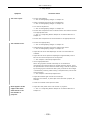
1. Using the equipment
This equipment should be used for photographic purposes only. Do not attempt to use it for any other
purpose.
2. Do not disassemble or repair the equipment
The DS-L1 and DS AC adapter contain high-voltage power supplies. Never attempt to disassemble or
repair the equipment by yourself; doing so may result in electric shock or equipment failure. Never
attempt to disassemble any part of the equipment unless instructed to do so in this manual. If you
notice any problems with the equipment, turn off the power and contact your nearest Nikon
representative.
3. DS AC adapter
Be sure to use a dedicated AC adapter. Use of any other AC adapter may result in fire or electric shock.
4. Power cord
To prevent electric shock, always turn off the POWER switch on the DS-L1 when plugging in or
unplugging the power cord. For the DS-U1, use only the specified power cord. The specifications for the
specified power cord are given below. Using another power cord may lead to fire or other hazardous
conditions.
Because this equipment falls under the category of electric shock protection class I, always make sure
it is grounded to a protective ground terminal. If you misplace or damage the power cord, contact your
nearest Nikon representative.
• When using the product in 100-120 V AC regions:
Use an UL-listed detachable power cord set.
3 conductor grounding Type SVT. No.18 AWG, 3m long maximum, rated at 125V AC minimum
• When using the product in 220-240 V AC regions:
Use only an EU/EN-approved three-conductor power cord set.
3 conductor grounding Type H05VV-F, 3m long maximum, rated at 250V AC minimum
5. Handling
•
To prevent malfunctions or overheating due to short circuits, do not allow this equipment or any
other device used with it to become wet. Never insert any foreign objects or materials into the
equipment. If the equipment gets wet, or if foreign matter (e.g., a scrap of paper) gets inside the
equipment, turn off the DS-L1’s POWER switch and unplug the power cord from the outlet. Then
contact your nearest Nikon representative.
•
Do not bend or twist the cables with undue force. Doing so may damage the cables and result in
fire.
•
Do not place a cloth or paper on the DS-L1 or DS AC adapter. Doing so may cause heat to collect
inside the equipment, resulting in fire.
- ii -
1. Installation environment
•
Do not use this equipment in locations subject to high temperatures, high humidity, vibration, or
•
When used for an extended period of time, the DS-L1 may become hot. Do not place the DS-L1 on
excessive amounts of dust. Doing so may result in fire or malfunction.
a surface that cannot withstand heat (such as vinyl or plastic). Always install the equipment with a
surrounding clear area of 100 mm or more.
•
When using the fitting holes on the back of the equipment to install it, always use metal fixtures
that can support the weight of the DS-L1 (without directly attaching the equipment to the wall).
Leave a clearance of 100 mm or more from the wall surfaces and periphery.
2. Always turn off power when setting up the equipment or when
connecting/disconnecting cables.
To prevent damage or malfunction, always turn off the DS-L1’s POWER switch when setting up the
equipment or when connecting or disconnecting cables.
3. Connect only the devices specified to the connectors.
To prevent damage to the equipment, connect only the devices specified to the connectors on the
DS-L1, the DS camera head, or the DS Remote Controller DS-RC.
4. Cautions on setup, installation, and storage of the equipment
•
Be careful to avoid pinching your fingers or hands in the equipment during installation.
•
To prevent damage to the equipment, avoid subjecting it to physical shock or violent vibrations
•
If you will not be using the equipment for an extended period of time, unplug the power cord from
•
Store equipment in a location where it will not be subject to vibrations or excessive amounts of
during installation.
the power outlet.
dust.
•
Avoid storing the equipment in hot, humid locations.
- iii -
CONTENTS
CONTENTS
I
Before Use ............................................................................................. 1
1 Types of DS Camera Head ........................................................................... 1
2 Components .............................................................................................. 2
II
Peripheral Equipment .............................................................................. 3
III
Names of Parts and Their Functions ........................................................... 6
1 DS Camera Control Unit DS-L1..................................................................... 6
2 DS Camera Head.......................................................................................... 9
3 DS Remote Controller DS-RC (Optional) ........................................................ 9
IV
Connecting and Installing the Equipment.................................................. 10
1 Connection Diagrams ................................................................................ 10
2 Installing the DS-L1.................................................................................. 12
3 Connection Methods ................................................................................. 13
V
Microscope Adjustment .......................................................................... 17
VI
Basic Operations ................................................................................... 20
1 Preparations Before Photographing ............................................................. 21
1.1 Using Various Input Devices .....................................................................21
1.1.1
1.1.2
1.1.3
1.1.4
Using
Using
Using
Using
the DS-L1 Panel Switches ............................................................21
the DS Remote Controller DS-RC ..................................................22
a Mouse ....................................................................................23
a Keyboard ................................................................................24
1.2 Notes on Using a CF Card ........................................................................25
1.3 Menu Configuration and Method of Displaying a Menu ..................................26
1.3.1
1.3.2
Menu Configuration .............................................................................26
Method of Displaying a Menu ................................................................27
1.4 Initial Settings........................................................................................28
1.4.1
1.4.2
1.4.3
1.4.4
1.4.5
1.4.6
Date and Power-save Settings—Additional Settings ..................................28
Image File Settings—File Settings ..........................................................30
Startup Condition Settings—Power On Settings........................................36
Adjusting Monitor Output for an External Monitor .....................................37
Settings for Direct Print........................................................................38
Settings for Connecting a Microscope .....................................................39
2 Photographing Images .............................................................................. 40
2.1 Adjusting Camera Operation and Exposure
for Better Picture Quality—CAM Menu ........................................................40
2.1.1
2.1.2
2.1.3
2.1.4
2.1.5
Simple Photography—Easy Menu ...........................................................40
Special Photography on the Easy Menu—DF/FL Scene Mode.......................44
Fine Adjustment before Photographing—Advn. Menu ................................46
Special Photography on Advn. Menu —Fluorescent Photographing
or Dark Subject Photographing..............................................................56
Special Photography on Advn. Menu – Stroboscope Photographing .............57
- iv -
CONTENTS
2.2 Using a CF Card......................................................................................58
2.2.1
2.2.2
2.2.3
Saving an Image to a CF Card—REC Menu ..............................................58
Reproducing Images from a CF Card—VIEW Menu....................................61
Using Dual-Window Display to Compare with the Reference Image .............62
2.3 Outputting Images Directly to a Printer ......................................................63
2.3.1
2.3.2
Printing an Image................................................................................63
Various Print Related Settings ...............................................................63
3 Measuring Two-point Distance or Entering Information—TOOL Menu............... 65
3.1 Outline of the TOOL Menu ........................................................................65
3.2 What is an Overlay? ................................................................................67
3.3 Entering a Comment on the Image............................................................68
3.3.1
3.3.2
3.3.3
Free-form Drawing ..............................................................................68
Using the Count Marker (to Count the Number of Points) ..........................69
Entering Textual Comments ..................................................................70
3.4 Measuring on the Screen .........................................................................71
3.4.1
3.4.2
3.4.3
3.4.4
3.4.5
3.4.6
Performing Calibration and Saving Values ...............................................71
Calling the Calibration Value .................................................................73
Measuring the Distance between Two Points............................................73
Measuring perpendicular distance ..........................................................75
Measuring angles ................................................................................76
Measuring circles.................................................................................77
3.5 Adjusting the Subject Position and Comparing Sizes ....................................78
3.5.1
3.5.2
3.5.3
3.5.4
3.5.5
Using Crosshairs to Adjust the Subject Position........................................78
Using a Scale to Measure the Subject Size ..............................................80
Using XY Scales to Measure the Dimensions of the Subject........................81
Creating a Translucent Image and Comparing It to a Live Image ................82
Measuring vertical and horizontal distances .............................................83
4 Using the DS-L1 via a Network................................................................... 84
4.1 Typical Method of Use .............................................................................84
4.2 Network Settings ....................................................................................86
4.2.1
4.2.2
Items Needing Confirmation .................................................................86
Setting Essential Items—Network Settings ..............................................87
4.3 Operating the DS-L1 from a WEB Browser ..................................................90
4.3.1 Setting the WEB Browser......................................................................90
4.3.1(1) When Using Internet Explorer...........................................................90
4.3.1(2) When Using Netscape......................................................................92
4.3.2 Using WEB Screens .............................................................................94
4.4 Using FTP Commands to Operate the DS-L1 ............................................. 101
4.4.1
Using FTP Commands to Get DS-L1 Image Files from a PC ...................... 101
4.5 Using Telnet Commands to Operate on the DS-L1 ..................................... 102
4.6 Saving Images to an FTP Server PC from the DS-L1................................... 103
4.6.1 Setting the FTP Server Functions of the PC............................................ 103
4.6.1(1) When Using Windows NT Workstation Ver. 4.0 .................................. 103
4.6.1(2) When Using Windows 2000 Professional and XP Professional ............... 105
4.6.1(3) When Using Mac OS X ................................................................... 108
4.6.2 Setting External Servers of the DS-L1—Network Settings ........................ 110
4.6.3 Saving Image Files in the FTP Server ................................................... 112
-v-
CONTENTS
4.6.3(1)
4.6.3(2)
Using the CAPTURE Button to Save Image Files ................................ 112
Using the CAM Menu to Save Image Files ......................................... 113
5 Using the DS-L1 when Connected to a PC by a USB Cable ................................. 115
5.1 Recommended Operating Environment .................................................... 115
5.2 Connecting the DS-L1 and a PC .............................................................. 117
5.3 Using the DS-L1 in Windows 2000........................................................... 118
5.3.1
5.3.2
5.3.3
5.3.4
5.3.5
Installing the Device Driver................................................................. 118
Outline of the Disk Drive .................................................................... 119
Using the Media Drive ........................................................................ 121
Using the CCD Image Drive ................................................................ 122
Removing the DS-L1 from the PC ........................................................ 124
5.4 Using the DS-L1 in Windows XP .............................................................. 125
5.4.1
5.4.2
5.4.3
5.4.4
5.4.5
Installing the Device Driver................................................................. 125
Outline of the Disk Drive .................................................................... 126
Using the Media Drive ........................................................................ 127
Using the CCD Image Drive ................................................................ 128
Removing the DS-L1 from the PC ........................................................ 130
6 Using the Microscope Control ................................................................... 131
6.1 Overview............................................................................................. 131
6.2 Menu Overview .................................................................................... 131
6.2.1
6.2.2
6.2.3
6.2.4
6.2.5
6.2.6
Microscope Control Menu 1 ................................................................. 137
Microscope Control Menu 2 ................................................................. 145
Microscope Status Display/Microscopy Setup Menu (MIC Info Menu) ......... 148
Ergo Controller button information display menu.................................... 151
Connecting a Motorized U-EPI ............................................................. 152
Connecting a Modular Microscope ........................................................ 152
6.3 Autofocus Precautions ........................................................................... 153
VII
Care and Maintenance ..........................................................................156
1 Cleaning the System............................................................................... 156
2 Storage................................................................................................. 156
VIII Troubleshooting ...................................................................................157
1 Power Supply......................................................................................... 157
2 Image Output ........................................................................................ 158
3 Photographing and Saving ....................................................................... 160
4 Abnormal Behavior ................................................................................. 160
5 Networking ............................................................................................ 161
6 USB ...................................................................................................... 164
7 Microscope Control from the DS-L1........................................................... 166
8 Before Contacting Us .............................................................................. 166
IX
Technical Specifications ........................................................................167
1 DS Camera Control Unit DS-L1................................................................. 167
2 DS Camera Head.................................................................................... 169
- vi -
CONTENTS
3 DS Remote Controller DS-RC ................................................................... 169
4 DS AC adapter ....................................................................................... 170
5 Overall Specifications.............................................................................. 170
- vii -
I Before Use
1
Types of DS Camera Head
I
Before Use
1
Types of DS Camera Head
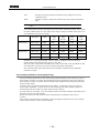
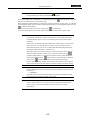
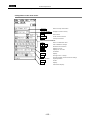
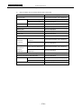
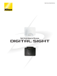
The following five DS camera head models are available. The features of the DS camera head
will vary depending on the model purchased. Before use, identify your DS camera head model.
The name of the model is indicated
near the mount-cap fitting position
of the DS camera head.
•
DS camera head models and features
DS camera head
model name
Image pickup device
Cooling
function
Body
color
DS-5M
2/3-inch, color, 5,240,000 pixels
White
DS-2Mv
1/1.8-inch, color, 2,110,000 pixels
White
DS-2MBW
1/1.8-inch, black and white,
2,110,000 pixels
White
DS-5Mc
2/3-inch, color, 5,240,000 pixels
Yes
Black
DS-2MBWc
1/1.8-inch, black and white,
2,110,000 pixels
Yes
Black
For detailed information on the features of each DS camera head model, refer to "Chapter
IX Technical Specifications."
•
Indication of DS camera head model name
In this manual, the product names, "DS Camera Head DS-5M," "DS Camera Head
DS-2Mv," "DS Camera Head DS-2MBW," "DS Cooled Camera Head DS-5Mc," and "DS
Cooled Camera Head DS-2MBWc" are abbreviated "DS-5M," "DS-2Mv," "DS-2MBW,"
"DS-5MC," and "DS-2MBWc," respectively.
The manual uses the term "DS camera head" when referring to all of these models.
•
Illustrations in the manual
In this manual, illustrations of LCD monitor screens such as menu displays are based on
the DS-5Mc. Differences are indicated where displays vary depending on DS camera head
model.
-1-
I Before Use
2
Components
Components
2
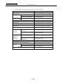
Check to see that all the items listed below are provided in the package.
If any items are missing, contact your nearest Nikon representative immediately.
1
DS Camera Control Unit DS-L1
5
DS camera head
C mount cap
Camera cable, 3 m
(E229586)
2
Instruction manual
6
DS Remote Controller DS-RC
Remote cable
(optional)
(E120411)
3
DS AC adapter
7
Direct Print License (optional)
4
Power cord
8
C mount adapter (optional)
9
Microscope Control License (optional)
-2-
II Peripheral Equipment
II
Peripheral Equipment
(1) Analog RGB input display
Although the DS-L1 contains a 1,024 × 768 (XGA) 6.3-inch liquid crystal display, you may need an
external display if you want to observe images on a larger screen or at a higher 1,280 × 1,024
resolution (SXGA).
Prepare an SXGA 60 Hz or XGA 60 Hz TTL-synchronized display available for use with PCs. For
best results, we recommend SXGA monitors.
SXGA: 1,280 × 1,024, 60 Hz (non-interlaced)
XGA: 1,024 × 768, 60 Hz (non-interlaced)
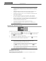
When shipped from the factory, the equipment is set for XGA output. If you’ve set your
equipment to SXGA to start up and are using a display that can only be synchronized to XGA
timing, hold down the MENU button on the DS-L1 when powering up. Be sure to hold down the
MENU button until the DS-L1 has started up. This forcibly sets the DS-L1 to internal monitor
output and external XGA output modes when it starts up.
After the DS-L1 has started up, set to XGA in Power On Settings of the SETUP menu and save
your settings.
NOTE: If you are using an LCD display or LCD projector, we recommend adjusting
its clock phase and clock pitch.
(2) USB mouse
You'll need a USB mouse to access functions available only from the mouse (e.g., screen scroll
while using the electronic zoom, TOOL functions such as length measurement or the pen drawing
function, or histograms). The mouse can also be used for various menu settings and operations.
Be sure to use a USB mouse recommended by Nikon. (Not every USB mouse is compatible with
the DS-L1.)
(3) USB keyboard
Although you can enter photographed data and comments using a mouse, it's easier to enter
such information with a keyboard. Use a keyboard recommended by Nikon. (Not every USB
keyboard is compatible with the DS-L1.)
-3-
II Peripheral Equipment
(4) USB hub
You'll need a USB hub to use a mouse, keyboard, and printer at the same time. Use a USB hub
recommended by Nikon. (Not every USB hub is compatible with the DS-L1.)
Only one hub can be connected to the DS-L1. If your keyboard is equipped with a USB hub, use
this hub.
(5) USB printer
Use the specified Mitsubishi CP900D or a printer which supports PictBridge Standard. You must
purchase a license to use the printer. Contact your nearest Nikon representative for more
information.
Restrictions will be displayed on the print screen if you attempt to use the printer without
obtaining a license. Refer to “1.4.5 Settings for Direct Print” in Chapter VI for details on how to
obtain a license.
(6) CF card
A CF card is needed to record or reproduce photographed data to or from a CF card.
We recommend a Type I- or Type II-compliant CF card or CF+ Type II microdrive (1 to 4 GB).
(7) C mount lens
A C mount lens is required to photograph subjects other than photomicrographs. Any lens that
satisfies the following conditions may be used:
•
Protrudes no more than 10 mm from the mount surface into the camera.
•
The image circle is 2/3" for the DS-5M and DS-5Mc and 1/1.8" for the DS-2Mv, DS-2MBW,
and DS-2MBWc. Use a lens for 2/3" or larger (e.g., 1”).
•
When using diaphragm settings brighter than F2.8, you may observe slight light falloff
around the periphery.
(8) Network connection cable
You'll need a network connection cable to save image data on another server or to control the
DS-L1 from another computer over a network. Use a cable for 100Base-TX (Category 5 or 6).
To satisfy EMC standards, use a shielded cable.
When connecting the DS-L1 to a LAN, use a straight cable. When connecting the DS-L1 directly
to a PC, use a crossed cable.
(9) USB cable
You'll need a USB cable to save image data to a PC or to print directly to a printer via USB. We
recommend using a USB 2.0-compliant AB-type cable for connections to a PC and an AB-type
cable for connection to a printer.
-4-
II Peripheral Equipment
(10) Personal computer (PC)
A PC is required for remote control of the DS-L1 or to handle image data on other media. A PC
can be connected to the DS-L1 via USB or over a network. For connect a PC to a network, we
recommend the following configuration:
OS:
Windows 98/NT/2000/XP
Macintosh OS 8.6/9.2/X
Memory:
64 MB or more
Browser:
Windows
Internet Explorer 5.5/6.0
Netscape 6.2/7.0
Macintosh
Netscape 6.2/7.0
Although Nikon has confirmed that the DS-L1 operates properly under the above conditions,
DS-L1 operations cannot always be guaranteed, since they are affected by OS or browser
versions and by various software settings.
(11) Nikon 80i/90i Microscope / LV150A Industrial Microscope
If you have a Nikon 80i/90i microscopes equipped with a digital imaging head, you can purchase
a license to control the microscope or display its status using the menus on DS-L1. To connect
your Nikon 80i/90i microscope to the DS-L1, use the USB cable provided with the microscope.
For information on purchasing a license, please contact the nearest Nikon office or distributor.
To connect the LV150A industrial microscope, Nikon specifies the USB-232C cable. This cable
enables display of nosepiece status. (No license required.)
-5-
III Names of Parts and Their Functions
1
DS Camera Control Unit DS-L1
III
Names of Parts and Their Functions
1
DS Camera Control Unit DS-L1
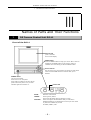
Front of the DS-L1
Internal LCD
1,024 × 768 dots
6.3-inch LCD display
MENU button
Press the MENU button to bring up a menu. After a menu is
displayed, the MENU button can be used to confirm a
selected menu command, just like the ENTER button.
Cursor buttons
Use one of the four cursor buttons to choose an item within
a menu and the MENU button to confirm what you’ve
selected.
POWER switch
This is a push switch.
Press it to turn on the power.
Press again to release it and turn off the
power. When the power is on, the LED
Freeze LED
indicator lights and remains on.
ZOOM:
FREEZE:
Electronic zoom button
Freeze (pause) button
The freeze LED lights when the display is frozen.
CAPTURE:
Saves an image to the destination that you selected in
Additional Settings. The destination to which you have saved
or printed is indicated by an LED.
CF CARD / PRINT / LAN
-6-
III Names of Parts and Their Functions
1
DS Camera Control Unit DS-L1
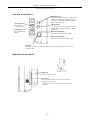
Left side of the DS-L1
USB device port
Connect a PC to this port with a USB cable to
send and receive data to and from the PC.
Or connect a PictBridge-supporting printer to
perform the direct print.
12 V DC output
USB host port
This output is
Use this port to connect a USB mouse, USB
currently unused.
keyboard, USB printer (CP900D), or Nikon
12 V DC input
microscope.
Use a dedicated AC
Network Tx indicator
adapter.
Lights when sending data to a LAN.
Network Rx indicator
Lights when receiving data from a LAN.
LAN port
Connect the DS-L1 to a LAN with a LAN cable to exchange data with a PC or server
through a LAN.
Right side of the DS-L1
Stand arm
Extract the arm to use it.
CF card slot
Insert a CF card into this slot to save or reproduce
data to or from the card.
* Make sure you're inserting the card in the correct
direction.
-7-
III Names of Parts and Their Functions
1
DS Camera Control Unit DS-L1
Rear of the DS-L1
RGB connector
Camera connector
Use this connector to
Connect the DS camera head to this connector.
connect an external
* Always be sure to turn off the power before connecting or
monitor.
disconnecting the camera head to or from this connector.
Failure to do so may result in malfunction.
External interface input
Connect the DS Remote Controller DS-RC here, and you can perform
freeze and capture operations from the DS-RC. A foot switch, etc.,
may also be used, providing it meets the interface specifications.
Refer to "3 Connection Methods" in Chapter IV for details on the
interface specifications.
External interface output
Connect a stroboscope or other external device here. This output
generates a synchronizing signal when capturing an image,
enabling the strobe light to be turned on synchronously.
Refer to “3 Connection Methods” in Chapter IV for details on the
interface specifications.
-8-
III Names of Parts and Their Functions
2
DS Camera Head
DS Camera Head
2
Tripod mount
This mount can be used to mount
the DS camera head on a tripod,
Top
Rear
Bottom
C mount cap
CAMERA OUT connector
Protects the C mount
from dust.
C mount
When taking microphotographs, mount
the C mount adapter here before
connecting to the microscope.
When taking other photographs,
attach the C mount lens here.
DS Remote Controller DS-RC (Optional)
3
To EXT.IN connector
Connect the cable supplied with the unit from
this connector to the EXTERNAL IN connector
on the DS-L1.
FREEZE button
CAPTURE button
Freezes the current
Saves image data. A destination where image
image as a still
data is saved (a CF card, server via FTP, or
picture. To release
output directly to a printer) can be assigned.
the frozen image,
Above functions can be assigned to the button in
press the button
Additional Settings of the SETUP menu.
again.
-9-
IV Connecting and Installing the Equipment
1
Connection Diagrams
IV
Connecting and Installing the Equipment
1
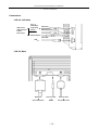
Connection Diagrams
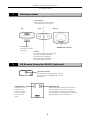
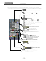
Schematic diagram
DS-L1
PC or a PictBridgesupporting printer
USB cable
USB equipment, mouse, keyboard, printer,
and Nikon misroscope
LAN cable
CF card
DS AC adapter
RGB cable
DS camera cable
LAN
DS-RC
DS camera head
- 10 -
IV Connecting and Installing the Equipment
1
Connection Diagrams
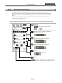
Connectors
· DS-L1 Left side
PC or a
PictBridgeUSB mouse
supporting
USB keyboard
printer
←
USB cable
USB equipment
Printer
Microscope
DS AC adapter
LAN cable
LAN ←
· DS-L1 Rear
RGB cable
Remote cable
↓
↓
↓
External monitor
DS-RC
DS camera head
- 11 -
Remote cable
IV Connecting and Installing the Equipment
2
2
Installing the DS-L1
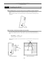
Installing the DS-L1
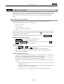
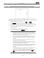
When installing the DS-L1 on a flat surface such as a desktop by using the stand arm
Extract the stand arm from the DS-L1 and place it at an angle of 5 to 10 degrees, as shown
below.
Leave a clearance of about 100 mm around the DS-L1 to prevent heat from collecting near the
equipment.
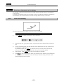
When attaching a commercially available arm to the DS-L1
Any commercially available VESA standard-compliant 75-mm arm, UL1678-suited stand and
mount can be attached to the DS-L1. When doing so, make sure the following specifications are
met:
DS-L1 weight:
1.3 kg
Fitting screw hole: M4, 7-mm deep
Tightening torque: 80-120 N·cm
Leave a clearance of about 100 mm around the DS-L1 to prevent heat from collecting near the
equipment.
M4 screw holes
Arm
Side view of the DS-L1
Rear view of the DS-L1
- 12 -
IV Connecting and Installing the Equipment
3
Connection Methods
Connection Methods
3
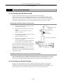
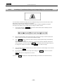
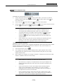
(1) Connecting the DS Camera Head
Be sure to turn off the power for the DS-L1 before making any connections.
Connect one end of the camera cable supplied with the unit to the CAMERA connector on the
DS-L1 and the other end to the CAMERA OUT connector on the DS camera head. Squeeze the
locking tabs on the connector as you plug in the connector. When the connector is plugged in all
the way, the locking tabs return to their original positions, locking the connector in place.
Mounting the DS camera head on a microscope
1)
Remove the C mount cap from the C mount
on the DS camera head.
2)
To CAMERA connector
Make sure there is no dust on the C mount
adapter.
If there is, use an air blower or similar
DS camera head
C mount
means to remove it.
3)
on the DS-L1
Screw the C mount adapter into the C mount
C mount adapter
on the DS camera head.
Screw it in as far as it will go.
4)
Insert the C mount adapter into the vertical
Vertical tube of microscope
tube of the microscope.
Use the clamping screw on the vertical tube
to secure the C mount adapter in place.
You can also attach a relay lens. We recommend
the x0.7 relay lens for the DS-5M and DS-5Mc. We
recommend the x0.55 relay lens for the DS-2Mv,
DS-2MBW, and DS-2MBWc.
When you have mounted the DS camera head on a
microscope, be sure to read "Chapter V Microscope
Adjustment" as well.
Installing a third-party C mount lens on the DS camera head
Select a mountable lens (see "Chapter II Peripheral Equipment"), then screw it into the C mount.
Note that the image quality produced by this product is tuned for microphotography. The tripod
mount on the DS camera head can also be used to mount the DS camera head on a tripod.
(2) Connecting an External Display
Be sure to turn off the power for the DS-L1 and the display before making any connections.
Connect one end of the D-sub 15-pin connecting cable supplied with the unit to the RGB
connector on the DS-L1 and the other end to the D-sub 15-pin connector on the display. Secure
the connections, using a screwdriver to tighten the screws on the cable connectors.
- 13 -
IV Connecting and Installing the Equipment
3
Connection Methods
(3) Connecting USB Peripheral Equipment
Be sure to turn off the power for the DS-L1 before making any connections.
When using a USB mouse, USB keyboard, USB printer (Mitsubishi CP900D), or Nikon 80i/90i
microscope independently, connect the device directly to the USB-H connector on the DS-L1.
When using USB devices simultaneously, connect them to a USB hub.
Only one USB hub can be connected to the DS-L1.
If your keyboard is equipped with a USB hub, use the hub built into your keyboard.
(4) Connecting to a PC or a PictBridge-Supporting Printer with USB Cable
When connecting to a PC, connect one end of the USB 2.0 cable (AB type) to the USB connector
on the PC and the other end to the USB-D connector on the DS-L1.
When connecting to a PictBridge-supporting printer, connect the PictBridge-supporting printer
and the USB-D connector on DS-L1 with a USB cable (AB type).
(5) Connecting the DS Remote Controller DS-RC
Be sure to turn off the power for the DS-L1 before making any connections.
Connect one end of the remote cable supplied with the unit to the EXTERNAL IN connector on
the DS-L1 and the other end to the TO EXT.IN connector on the remote controller.
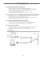
(6) Connecting to a Network
Be sure to turn off power for the DS-L1 and the equipment to be connected before making any
connections. In addition, be sure to consult your network administrator.
Make the connections as shown below. We recommend using cables and hubs designed for
100BASE-TX use.
Connecting to a LAN
Left side of the DS-L1
Network
Third-party 10/100BASE-TX
(category 5) cable (straight)
To Ethernet
connector
Third-party 10/100BASE-TX
(category 5) cable (straight)
PC
- 14 -
Hub
IV Connecting and Installing the Equipment
3
Connection Methods
Connecting to a PC without going through a LAN
Left side of the DS-L1
Third-party 10/100BASE-TX
(category 5) cable (crossed)
To Ethernet
connector
PC
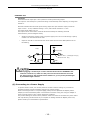
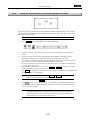
(7) Connecting External I/O Devices
Be sure to turn off the power to the DS-L1 and any equipment to be connected before making
connections.
When an external device is connected to the EXTERNAL IN connector on the DS-L1, the image
can be frozen or captured by trigger input from the external device.
Furthermore, if an external device is plugged into the EXTERNAL OUT connector, a strobe
synchronizing output can be obtained when capturing an image.
If you are preparing your own external device, use a device that satisfies the specifications
shown below.
Connector: 3.5-mm diameter stereo pin jack (EXTERNAL IN connector)
Connector: 2.5-mm diameter stereo pin jack (EXTERNAL OUT connector)
Pin 3: GND
Pin 2
Pin 1
EXTERNAL IN
Functions
Pin 1: FREEZE
Pin 2: CAPTURE
You will not be able to capture desired images at precise, split-second moments. Use of this
input is not suitable for photographing fast-moving objects using a sensor.
3.3V
Pin 1 or 2
3.3kΩ
Activated when the switch is ON (closed)
DS-L1 side
Required pulse width: 10 ms or more
GND
Pin 3
- 15 -
IV Connecting and Installing the Equipment
3
Connection Methods
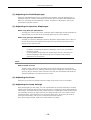
EXTERNAL OUT
Functions:
Extended external output pins 1 and 2, both for strobe synchronizing output
This output is used mainly for synchronized firing of a stroboscope when capturing an image with
the DS-L1.
Electrical characteristics of strobe synchronizing output are open-collector output, maximum
input current = 10 mA, withstand voltage = 24 V, and internal resistance = 100 Ω.
The output pulse width is 67 ms.
This output can be connected to external devices that satisfy the following electrical
characteristics. (See the diagram below.)
•
Strobe synchronizing output is tied to a power supply line of 24 V or less through a pullup
resistor R on the external device side.
•
Inputs on the DS-L1 and external user device sides have the same GND potential or are
left floating.
E≤24V
100Ω
R≤E/10(kΩ)
Pins 1 and 2
ON-time level
(100xE)/(R+100)(V)
OFF-time level E(V)
Pin 3
GND
DS-L1 side
GND
External device side
When plugging a stroboscope or other external device into the EXTERNAL OUT
connector of the DS-L1, make sure the power for the external device is turned
off. If the power for the external device remains on, your eyes may be damaged
by unintended light emission.
(8) Connecting to a Power Supply
To prevent electric shock, turn off the power for the DS-L1 before making any connections.
Complete all other connections before plugging into a power supply.
When connecting the DS-L1 to a power supply, always use the specified AC adapter (DS AC
adapter) to which a dedicated power cord should be connected. Using the wrong AC adapter or
power cord may lead to a fire or other dangerous conditions.
This product belongs to electric shock protection class I and must be connected to a power outlet
with a protective ground terminal. If you misplace or damage the DS AC adapter power cord,
please contact your nearest Nikon representative.
- 16 -
V Microscope Adjustment
V
Microscope Adjustment
When the camera head is mounted on a microscope, adjust the microscope as described below.
(1) Use the Appropriate Filters
When capturing a color image:
Insert the NCB filter into the optical path.
When capturing a black & white image:
Insert the appropriate filter into the optical path, depending on the photographic purpose.
Generally, inserting a green interference filter (GIF) will heighten contrast. Contrast is
enhanced by inserting a filter with a color complementary to the specimen.
Supplement
*
The method for inserting and removing a filter varies from microscope to
microscope. Refer to your microscope’s instruction manual.
*
A third-party color compensation filter (CC filter) can be inserted into the
illumination optical path of the microscope to compensate for changes in
color balance caused by the length of the exposure time.
*
When using a phase contrast microscope or an interference microscope (two
luminous fluxes or multiple luminous fluxes), you can enhance contrast
using a green interference filter (GIF) or a monochrome interference filter
(IF).
*
We recommend simultaneous use of an NCB filter and a green interference
filter (GIF) for the DS-2MBW and DS-2MBWc.
*
Some microscopes may require a heat-wave absorption filter.
Terms
What is an NCB filter?
An NCB (neutral color balance) filter is a color-balancing compensation filter used to adjust
color temperature to daylight values in microscopes that use a halogen bulb as a light
source.
What is a complementary color?
For example, green and magenta, red and cyan, and blue and yellow are all pairs of
complementary colors. When complementary colors overlap, their respective hues cancel
each other out.
- 17 -
V Microscope Adjustment
(2) Adjusting the Field Diaphragm
Adjust the field diaphragm so that it circumscribes the viewfield. The field diaphragm has a
significant impact on contrast, especially for fluorescent specimens against dark backgrounds.
Make sure you adjust the field diaphragm correctly. For details on adjustment, refer to your
microscope’s instruction manual.
(3) Adjusting the Aperture Diaphragm
When using diascopic illumination:
Generally, the numeric value of the condenser aperture diaphragm should be adjusted to
approximately 70% to 80% of the numerical aperture (N.A.) of the objective.
When using episcopic illumination:
Generally, the aperture diaphragm should be adjusted to approximately 70% to 80% of
the size of the pupil of the objective that can be seen by removing the eyepiece and
looking into the eyepiece tube.
Supplement
*
For details on adjusting the aperture diaphragm, refer to your microscope’s
instruction manual.
*
For photographed images that have greater depth of focus, close down the
aperture diaphragm. Note that closing down the aperture may limit the
performance of the objective.
Terms
What is depth of focus?
"Depth of focus" refers to the range along the axis of the field of view over which the
image is in apparent focus. Although reducing the aperture diaphragm extends the depth
of focus, doing so will also reduce resolution. Take this into consideration and adjust the
aperture diaphragm in accordance with your needs.
(4) Adjusting the Focus
Adjust the focus of the microscope so that the image can be clearly seen on the display.
(5) Adjusting the Lamp Voltage
When photographing a color image, the color reproducibility of the image depends on the lamp
voltage. When a halogen lamp is used as the light source, increasing the lamp voltage produces
a bluish light, while decreasing the lamp voltage produces a reddish light. Except in cases where
it is specifically necessary to adjust the tone, the voltage should be set to the proper level for
microphotography, which depends on the microscope being used. (Since this level varies for
each type of microscope, refer to your microscope’s instruction manual.)
If the lamp voltage changes, measure the white balance once again.
- 18 -
V Microscope Adjustment
(6) Adjusting the Exposure Time
Use an ND filter to adjust the illumination for the microscope to a level that yields a suitable
exposure time (generally 1/15 to 1/250 s). You can also adjust the camera sensitivity.
Terms
What is an ND filter?
An ND filter is a filter that affects only the amount of light passed, not the color balance of
the light. For example, an "ND2" filter cuts transmitted light in half, while an "ND16" filter
reduces transmitted light to 1/16th of actual levels.
(7) Effects of Ambient Light
When capturing a dark specimen with a fluorescent microscope, for example, ambient indoor
light may enter the optical path. Accordingly, interior lighting should be darkened for
photomicrography. Place caps on the binocular eyepiece to prevent light from entering through
the eyepiece.
(8) Effects of Vibration
Because photomicrography involves extremely high image resolution, the slightest vibration can
affect image quality. To insulate the microscope from vibration, set it on a solid, stable surface
on a solid floor. Using an anti-vibration table compatible with the microscope will further reduce
the effects of vibration. While actual microphotography is in progress, be careful to avoid
touching the microscope or the desk or stand on which it is positioned.
- 19 -
.SETUP.
VI Basic Operations
1
Preparations Before Photographing
VI
Basic Operations
Preface to Operating Instructions
The DS-L1 (Ver. 3.00 or later) supports the five camera heads listed below. If you change
camera heads, the DS-L1 control unit will automatically switch modes in response.
DS-5M
5-megapixel CCD / color / non-cooled
DS-5Mc
5-megapixel CCD / color / cooled
DS-2Mv
2-megapixel CCD / color / non-cooled
DS-2MBW
2-megapixel CCD / monochrome / non-cooled
DS-2MBWc
2-megapixel CCD / monochrome / cooled
(For detailed information on these cameras, refer to Chapter IX, "Technical Specifications.")
The following terms are used in this manual to refer to different cameras.
"5M cameras"
->
"2M cameras"
->
DS-5M and DS-5Mc
DS-2Mv, DS-2MBW, and DS-2MBWc
"Cooled cameras"
->
DS-5Mc and DS-2MBWc
"Non-cooled cameras"
->
DS-5M, DS-2Mv, and DS-2MBW
"Monochrome cameras"
->
DS-2MBW and DS-2MBWc
Example screenshots are based on the DS-5M.
When using 2M cameras, keep in mind that size specifications, such as image size, differ from
those of the 5M.
- 20 -
SETUP
VI Basic Operations
1
1
Preparations Before Photographing
Preparations Before Photographing
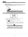
1.1
Using Various Input Devices
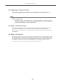
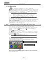
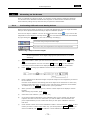
1.1.1
Using the DS-L1 Panel Switches
MENU button
Cursor buttons
ZOOM button
FREEZE button
CAPTURE button
MENU button (menu/enter button)
Pressing the MENU button brings up the CAM Easy menu. While the menu is displayed, use
this button as the ENTER button to confirm your selection.
- 21 -
.SETUP.
VI Basic Operations
1
Preparations Before Photographing
Cursor buttons
Use these buttons to select an icon in a menu or to increment or decrement a set value.
•
For an icon to increment or decrement a value such as the Gain icon on the CAM
menu
Position the cursor over the icon and press the MENU button to select the icon. The
color of the cursor frame changes to blue. Press the right or top cursor button to
increment the value or the left or bottom cursor button to decrement the value.
•
For a shutter speed
The value changes in the same way as described above. The right or top cursor
button lowers the shutter speed to increase exposure, whereas the left or bottom
cursor button increases the shutter speed to reduce exposure.
•
For a mode-select icon, such as one to choose an exposure method on the CAM
menu
Select an icon you want and use the right or top cursor button to select items in the
forward direction or the left or bottom cursor button to select items in the reverse
direction.
ZOOM button (electronic zoom button)
Use this button to apply an electronic zoom. The image zooms in or out at the
magnification selected for E.Zoom Step in Additional Settings of the SETUP menu.
FREEZE button (freeze button)
This button allows you to switch the state of a photographed image between freeze and
live.
CAPTURE button (capture button)
Use this button to save an image. This button can be assigned a save destination (CF card,
FTP server, or printer). The image will then be saved to the destination selected for
Capture Function in Additional Settings of the SETUP menu.
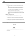
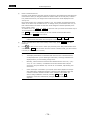
1.1.2
Using the DS Remote Controller DS-RC
FREEZE button
CAPTURE button
FREEZE and CAPTURE buttons
These buttons serve the same function as the FREEZE and CAPTURE buttons on the front
panel of the DS-L1.
- 22 -
VI Basic Operations
1
1.1.3
SETUP
Preparations Before Photographing
Using a Mouse
You can use a USB mouse with the DS-L1. Be sure to use a recommended mouse. Not every
USB mouse is compatible with the DS-L1.
While most normal operations involve left-clicking the mouse, some may require right-clicking.
For icons to set a value or select a mode, left- or right-clicking the mouse button allows you to
increment or decrement a value or select items in the forward or reverse direction.
•
For an icon to increment or decrement a value such as the Gain icon on the CAM menu
Left-clicking the icon increases the value, while right-clicking the icon reduces the value.
•
For a shutter speed
Left-clicking reduces the shutter speed to increase exposure; right-clicking increases the
shutter speed to reduce exposure.
•
For a mode-select icon, such as one to choose an exposure method on the CAM menu
Left-clicking lets you select items in the forward direction; right-clicking lets you select
items in the reverse direction.
Some functions are available only with the mouse. You will need a mouse to access all the
functions of the DS-L1. The following functions are not accessible without a mouse:
•
Electronic zoom scroll
•
Screen scroll when split into halves
•
Histogram display
•
Pen drawing function
•
Text input function
•
Count marking function
•
Two-point distance measurement function (including calibration)
•
Superimposed position adjustment
- 23 -
.SETUP.
VI Basic Operations
1
1.1.4
Preparations Before Photographing
Using a Keyboard
You can use a USB keyboard with the DS-L1. For frequent text or character entry, you'll find
using a keyboard most convenient. Be sure to use a recommended type of keyboard. Not all USB
keyboards are compatible with the DS-L1.
Alphanumeric characters in upper- or lowercase can be used with the DS-L1.
The function keys on the keyboard can be assigned various functions, such as displaying a menu,
freezing or the Capture button for quick operations.
Function key assignments on the USB keyboard
F1
CAM menu
F2
VIEW menu
F3
REC menu
F4
TOOL menu
F5
F6
MIC menu
F7
F8
F9
E.ZOOM–
F10
E.ZOOM+
F11
FREEZE
F12
CAPTURE
Back Space
Deletes one character during character entry
SHIFT + Backspace
Deletes the entire text during character entry
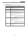
NOTE: The DS-L1 is factory set to a Japanese keyboard layout. If you wish to use
an English keyboard, issue the Telnet command shown below to change
keyboard settings. To revert to the Japanese keyboard, use the Telnet
command shown below to change keyboard settings.
w_KYBUS
Selects an English keyboard
w_KYBJP
Selects a Japanese keyboard
Settings you’ve changed will take effect upon restarting the DS-L1 after
executing the command.
For information on Telnet connections, refer to “4.5 Using Telnet Commands
for the DS-L1” in Chapter VI.
- 24 -
VI Basic Operations
1
1.2
SETUP
Preparations Before Photographing
Notes on Using a CF Card
Images can be saved to or reproduced from a CF card. Pay attention to the following when using
a CF card:
•
Use a Type-I or Type II-compliant CF card or microdrive.
•
Carefully read the user's manual provided with your CF card before using the card.
•
To format a CF card on your computer, use FAT12, FAT16 (Sometimes these are
expressed simply as FAT.), or FAT32. Depending on the OS used, you may not be able to
select a format.
•
The DS-L1 is able to format a CF card. CF cards preformatted in NTFS, that is, formats not
supported by the DS-L1, are formatted in FAT16. For detailed information on using the
formatting function, refer to “2.2.2 Reproducing Images from a CF Card–VIEW Menu” in
Chapter VI.
NOTE: CF cards formatted in other than NTFS may not be correctly formatted in
FAT16 depending on the formats used. In such cases, reformat those CF
cards in FAT12, FAT16, or FAT32 on your computer before use.
•
Insert the connecting side (with the connecting slot) of a CF card into the card slot, with
the label side facing toward you. Carefully note the direction and inclination of a CF card
when inserting.
•
Check to see that the CF card indicator LED is off before inserting or removing a CF card.
•
Do not remove a CF card or turn off power to the DS-L1 while the card is being accessed
(the LED indicator is on). Attempting to do so may result in loss of recorded data or
damage to the CF card.
- 25 -
.SETUP.
VI Basic Operations
1
Preparations Before Photographing
1.3
Menu Configuration and Method of Displaying a Menu
1.3.1
Menu Configuration
The menus available with the DS-L1 are listed below.
Shortcut menus
CAM (Easy / Advn. / Reg.)
Camera setting menus
VIEW
Save to or reproduce from CF card, two-screen
reproduction, CF card thumbnail
REC
Menus for saving images
TOOL
Menus for two-point distance measurement and other
tools
MIC
Microscope control menu
SETUP
Power ON Settings
Startup settings
Network Settings
Network settings
File Settings
File settings
Additional Settings
Other environment settings
*
Shortcut
Return to window
to return to the upper layer.
Buttons for frequently-used functions
(Freeze, Electronic zoom, AE lock, Print,
Save to FTP server, Save to CF card)
MIC INFO
Settings of the frequently used status display and
observation methods for the microscope
Common icons on CAM, VIEW, REC, TOOL and MIC menus
The icons listed below can be used in all menu screens:
Resizes the displayed menu.
Closes the menu.
Freezes the image.
Electronic zoom
- 26 -
VI Basic Operations
1
1.3.2
SETUP
Preparations Before Photographing
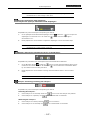
Method of Displaying a Menu
Follow the procedure described below to show or hide a menu or to switch between menus.
Using the MENU button on the main unit front panel
Press the MENU button to display the CAM Easy menu.
To change menus, select your desired tag with one of the cursor buttons and press the
MENU button (which functions as the enter button) to confirm.
button.
To close the menu screen, press the
Using the mouse
Right-clicking with the mouse displays a menu. The specific menu displayed depends on
the mouse pointer position on the screen when you right-click.
•
Top 1/3th of the screen:
CAM Easy menu
•
Middle of the screen:
CAM Easy menu and shortcut menu
•
Bottom 1/3th of the screen:
Shortcut menu
To close the menu screen, right-click anywhere outside the menu area.
Using the keyboard
Pressing a function key on the keyboard displays one of the following menus:
•
F1:CAM menu
•
F2:VIEW menu
•
F3:REC menu
•
F4:TOOL menu
•
F6:MIC menu
To change menus, select your desired tag on the current menu with a cursor button and
hit the Enter key on the keyboard to confirm.
- 27 -
.SETUP.
VI Basic Operations
1
1.4
Preparations Before Photographing
Initial Settings
When using the DS-L1 for the first time after purchasing, you must make the following
environment settings before photographing any image.
(1) Date and power-save settings
Set the unit clock and power-save timer.
(2) Image file-save related settings
Set an image file format and compression rate, the folder and file names in which to save
the file, and the source (photographing mode). Also make settings for entering camera
information or comments and for saving a log file at the same time.
(3) Startup condition settings
Set startup conditions for photography and display states.
To make these settings, display a menu and select the [SETUP] tag to enter the SETUP menu.
The correct procedures are detailed below.
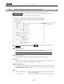
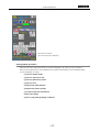
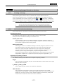
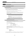
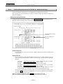
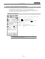
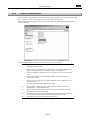
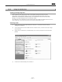
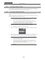
1.4.1
Date and Power-save Settings—Additional Settings
Display a menu and select the [SETUP] tag to enter the SETUP menu. Select
Additional...
from the SETUP menu to display the Additional Settings screen shown below.
Sets date and time.
Sets power-save timer.
Sets mouse speed.
Sets electronic zoom
magnification.
Assigns CAPTURE
button function.
When you have finished setting each item, press
press
Default
SAVE
to restore data to default values.
- 28 -
to save the data that has been set. Or
VI Basic Operations
1
SETUP
Preparations Before Photographing
Date:, Time:
Enter a date and time.
NOTE: If the DS-L1 remains turned off for extended periods, its internal timer may
slow down or stop. When the DS-L1 starts up, it displays the date and time
set in its timer (flashes for about 8 seconds). If you have shut off the DS-L1
for one week or longer, check the date and time shown on the DS-L1 when
you turn it back on.
Power Save Timer
If you leave the DS-L1 idle for a certain time, it will automatically switch to power-save
mode. You can set how long the DS-L1 will wait before switching to power-save mode.
Setting a value of “00” will disable the power-save function.
Pointer speed Low/Mid/High
Select the speed at which the mouse pointer moves across the screen when you move the
mouse.
E.Zoom Step
Select the magnification rate of the electronic zoom, at which rate the image is zoomed in
or out. (Two or more choices can be selected.)
Capture Function
Save to Card / Save to Server / Print
Select one of these functions to save to a CF card, to save to the FTP server, or to output
to a printer you want assigned to the CAPTURE button on the DS-L1 and the DS Remote
Controller DS-RC or to the CAPT. button on the menu. The CAPTURE button can be
assigned two or more functions at the same time.
External Out
This is an external interface output.
If you select ON, a strobe synchronizing signal is output from the EXTERNAL OUT
connector when capturing an image.
For normal use, we recommend selecting OFF. If you select ON, a time lag will occur in
external output with respect to the displayed image on the monitor.
Firmware Version
The number at the bottom-right indicates the firmware version.
The firmware version in the example shown is Ver = 220.0202.1717.040825. This is the
firmware Ver. 2.20.
300.****.****.** **** or later version is the firmware compatiple with 2M/5M cameras.
- 29 -
.SETUP.
VI Basic Operations
1
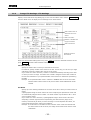
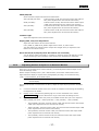
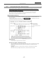
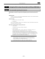
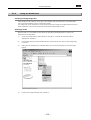
1.4.2
Preparations Before Photographing
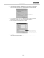
Image File Settings—File Settings
Display a menu and select the [SETUP] tag on it to enter the SETUP menu. Select
File Settings
from the SETUP menu to display the File Settings screen shown below.
Sets a folder name in
which files are to be
stored.
Sets a file name.
Enables or disables the
log input function.
Sets a file format.
Example screen for
5M cameras
When you have finished setting each item, press
press
Default
SAVE
to save the data that has been set. Or
to restore data to default values.
Card Dir, FTP Dir
Specify the folder name in which you want files to be stored.
For Card Dir, specify a folder name used in a CF card. For FTP Dir, you can use up to eight
characters to specify a folder name used in an FTP server.
If you select the “Auto” check box, a folder is created automatically according to the date
on which you save an image. The folder thus created is assigned a name that consists of
the first two characters of your specified folder name and the six characters representing
the date.
Example: If the specified folder name in Card Dir is IMGBOX with the “Auto” check box
selected and the date is 2005.03.28, then a folder named “IM050328” will be
created.
File Name
Specify up to four leading characters for the name of the file in which you want to save an
image.
A photographed image is saved under a file name comprising the specified file name and
an automatically assigned serial number. The serial number recycles back to No. 1 when
you turn off the power.
If you select the “Auto” check box, a photographed image is saved under a file name
comprising a total of eight characters representing the date and time (days, hours,
minutes, and seconds) at which you save the image. To avoid duplicate file names, we
recommend selecting Auto under most conditions.
Example: If the file name in File Name is DSL1 with the “Auto” check box selected and
the date is 2005.03.28 15:30:54, the image will be saved under the file name
“28153054.”
- 30 -
VI Basic Operations
1
SETUP
Preparations Before Photographing
Log
If you select the check box labeled “with LOG.txt,” the function for attaching a log (comment
statement) is enabled when you save an image. Writing information such as subject name,
number, and objective magnification in a log may facilitate future confirmation.
You can write up to 100 characters to a log when saving an image to a card or server, or
up to 32 characters when outputting to a printer.
Photographed data (including Nikon 80i/90i microscope data during photography) is also
contained in a log.
•
When you save an image in BMP format, the log is saved to a file named after the
image, with the extension “txt” added.
•
When you save an image in JPEG format, it is saved to a file named after the image
with the extension “txt” added.
Further, it is embedded in the image file as Exif information.
•
When you output an image directly to a printer, the log is printed as a comment.
NOTE: You can attach a log when saving an image even if you didn't select Log
during initial settings. Select the Append check box for Log on the REC
menu and enter a comment in the text box. Photographing information and
your comments will be saved in text format when you save the image.
File Type
Set a file format, an image size, and a compression rate.
TYPE:
Select “JPEG” or “BMP” as the format in which you want to save a file.
SOURCE:
Select the source type based on photography mode. This setting applies
when freezing images, saving image files, or printing images directly. Use
this setting to ensure the image quality level for saved images. You can
also use this setting to avoid switching CCD modes when freezing images.
For 5M cameras, choose "s5M" or "s1.3M."
For 2M cameras, choose "s2M" or "s800*."
For setting guidelines, refer to "Source Setting Guidelines (Photography
mode)" on the next page. If you set the source to the highest resolution
("s5M" for 5M cameras or "s2M" for 2M cameras) and select "Auto change
CCD mode," the display mode will adjust automatically to match the
camera shutter speed. For further details, refer to "Auto change CCD
mode" at the end of this chapter.
SIZE:
Setting the size of saved images.
For 5M cameras, choose "2560*1920," "1280*960," or 640*480."
For 2M cameras, choose "1600*1200," 800*600," or "400*300."
If you set the source to "s800*" and the display mode to "800*5" while
using 2M cameras, the actual image size will differ from the designated
size. Images will be saved at 800*560 resolution if you select "800*600"
and at 400*280 for "400*300." This means portions of the image at the
top and bottom will be cropped out.
Saving images as "400*300" JPEGs will produce 400*296 images,
cropping out a small portion of the bottom.
When using either 2M or 5M cameras and saving images for display from
CF cards again, the image size is changed to 1280*960. With 5M cameras,
images will still be saved at 1280*960 resolution, even if the specified
image size is "2560*1920." Likewise, with 2M cameras, images will be
saved at 1280*960 resolution for a specified image size of "1600*1200."
Specifying an image size of "800*600" will result in 640*480 resolution.
JPEG Quality:
If you select JPEG for the file format, select a compression rate (picture
quality) here.
- 31 -
.SETUP.
VI Basic Operations
1
Fine:
Preparations Before Photographing
Provides high picture quality but produces large images due to a low
compression rate.
Draft:
Provides low picture quality but small file sizes due to high compression
rates.
NOTE: You can also select the file format when saving an image from the REC
menu.
The following table gives the resulting file sizes for various image file settings. Since actual
file sizes of JPEG images can vary widely from image to image, the JPEG values given here
are intended to serve only as a guide.
File Type
5M cameras
2M cameras
BMP
JPEG
JPEG
JPEG
JPEG
Fine
Normal
Basic
Draft
2560*1920
14MB
4MB
1.8MB
1.2MB
900KB
1280*960
3.6MB
1.0MB
460KB
310KB
230KB
640*480
900KB
260KB
120KB
80KB
60KB
1600*1200
5.6MB
1.6MB
720KB
480KB
360KB
800*600
1.4MB
400KB
180KB
120KB
90KB
400*300
350KB
100KB
50KB
30KB
20KB
Separate R, G, and B channel data is stored. Overlay composites can be created by
incorporating colored drawings with a pen or other tool.
When you save overlays with the TOOL menu, keep in mind that it may be difficult to read
text information if the file is too small or features high JPEG compression.
We recommend saving files that include text information in BMP format at 1280*960
resolution or higher.
Source Setting Guidelines (Photography mode)
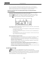
The source setting represents the CCD mode during image acquisition when you freeze, save, or
print images. The DS-L1 will switch CCD modes during image acquisition if the source setting of
saved images is a higher resolution than the display mode. (Note that switching CCD modes will
result in a brief delay.)
In certain cases, you should avoid switching CCD modes – for example, when you expect to
freeze images repeatedly. To keep the DS-L1 from switching CCD modes, display images in a
mode having resolution equal to or higher than the source setting.
The CCD mode will not switch if you view images saved at the lowest resolution (640*480 for 5M
cameras or 400*300 for 2M cameras).
On the other hand, the CCD mode will switch automatically if the display mode is set to
"C.Scan."
If the quality of saved images is important, choose the highest resolution for the source setting
("s5M" for 5M cameras or "s2M" for 2M cameras).
- 32 -
SETUP
VI Basic Operations
1
Preparations Before Photographing
Display mode
Performance
(CAM menu)
Frame
(fps)
5M
cameras
2M
cameras
Source / CCD mode switching
Progressive
rate
s5M
s1.3M
s2M
s800*
5Mi
3.75
No
No
--
--
1.3Mi
6.75
Yes
No
--
--
1.3Mp
7.5
{
Yes
No
--
C.Scan
15
{
Yes
Yes
--
--
2Mfull
15
{
--
--
No
No
800*6
20
{
--
--
Yes
No
800*5
30
{
--
--
Yes
No
C.Scan
30
{
--
--
Yes
Yes
Features of display modes
The various display modes offer different advantages, as described below.
5M cameras (Cameras suitable for high-resolution applications)
5Mi
An image area of 2560*1920 pixels is reduced for display at the monitor
resolution (1280*960/SXGA or 1024*768/XGA). The frame rate is 3.75 fps.
This display mode is useful when viewing images in great detail.
The CCD mode does not switch to match the shutter speed, so there are no
delays during image acquisition.
For this reason, we also recommend this mode when making long
exposures.
Interlaced display modes may cause color shifts with moving subjects.
1.3Mp
An image area of 1280*960 pixels is formatted for the monitor resolution.
The image is displayed at actual size (1280*960/SXGA) or reduced
(1024*768/XGA). The frame rate is 7.5 fps.
This display mode is useful when good performance with moving subjects is
required.
If the source is set to "s5M," the CCD mode will switch to match the shutter
speed, resulting in delays during image acquisition.
Progressive display modes eliminate color shifts, even with moving subjects.
We recommend using this display mode as the general display mode.
1.3Mi
An image area of 1280*960 pixels is formatted for the monitor resolution.
The image is displayed at actual size (1280*960/SXGA) or reduced
(1024*768/XGA). The frame rate is 6.75 fps.
This mode is four times more sensitive to light than other modes, making it
is particularly useful for dark subjects.
If the source is set to "s5M," the CCD mode switches to match the shutter
speed, resulting in delays during image acquisition.
Interlaced display modes may cause color shifts with moving subjects.
C.Scan
An area corresponding to the center of the image is formatted for the
monitor resolution. The image is displayed at actual size (1280*960/SXGA)
or reduced (1024*768/XGA). The top and bottom 1/4 are not displayed.
The frame rate is 15 fps.
- 33 -
.SETUP.
VI Basic Operations
1
Preparations Before Photographing
This display mode is useful when good performance with moving subjects is
required.
Regardless of the source setting, the CCD mode switches to match the
shutter speed, resulting in delays during image acquisition.
Progressive display modes eliminates color shifts, even with moving
subjects.
2M cameras
2Mfull
(Cameras suitable for applications requiring a high frame rate and
good motion performance)
An image area of 1600*1200 pixels is reduced for display at the monitor
resolution (1280*960/SXGA or 1024*768/XGA). The frame rate is 15 fps.
This display mode is useful when viewing images in great detail.
The CCD mode does not switch to match the shutter speed, so there are no
delays during image acquisition.
For this reason, we also recommend this mode when making long
exposures.
Progressive display modes eliminate color shifts, even with moving subjects.
We recommend using this display mode as the general display mode.
800*6
An image area of 800*600 pixels is enlarged for display at the monitor
resolution (1280*960/SXGA or 1024*768/XGA). The frame rate is 20 fps.
This display mode is useful when good performance with moving subjects is
required.
This mode is four times more sensitive to light than other modes, making it
is particularly useful for dark subjects.
If the source is set to "s2M," the CCD mode switches to match the shutter
speed, resulting in delays during image acquisition.
Progressive display modes eliminate color shifts, even with moving subjects.
800*5
An image area of 800*560 pixels is enlarged for display at the monitor
resolution (1280*960/SXGA or 1024*768/XGA). The top and bottom 40
pixels of the 1200 vertical pixels are cropped out and therefore not
displayed.
The frame rate is 30 fps.
This display mode is useful when good performance with moving subjects is
required.
If the source is set to "s2M," the CCD mode switches to match the shutter
speed, resulting in delays during image acquisition.
Progressive display modes eliminates color shifts, even with moving
subjects.
C.Scan
An area corresponding to the center of the image (560 pixels out of 1200
vertical pixels) is formatted for display at the monitor resolution
(1280*960/SXGA or 1024*768/XGA). The frame rate is 30 fps.
This display mode is useful when good performance with moving subjects is
required.
Regardless of the source setting, the CCD mode switches to match the
shutter speed, resulting in delays during image acquisition.
Progressive display modes eliminates color shifts, even with moving
subjects.
- 34 -
SETUP
VI Basic Operations
1
Preparations Before Photographing
Auto change CCD mode
Select "Auto change CCD mode" for automatic adjustment of the CCD mode to match the
camera shutter speed when the source is set to maximum resolution ("s5M" for 5M cameras or
"s2M" for 2M cameras).
This mode lets you observe bright subjects at high speed or dark subjects at high resolution
without manually adjusting the display mode.
However, note that the display mode will not adjust automatically when set to maximum
resolution ("5Mi" for 5M cameras or "2Mfull" for 2M cameras) or C.Scan.
Specifically, the display mode is adjusted as follows:
5M cameras
1.3Mp/1.3Mi
->
(Shutter speed: 1/3 second)
->
<-
(Shutter speed: 1/7 second)
<-
->
(Shutter speed: 1/7 second)
->
<-
(Shutter speed: 1/15 second) <-
5Mi
2M cameras
800*6/800*5
- 35 -
2Mfull
.SETUP.
VI Basic Operations
1
1.4.3
Preparations Before Photographing
Startup Condition Settings—Power On Settings
Display a menu and select the [SETUP] tag on it to enter the SETUP menu. Select
Power On Settings from the SETUP menu to display the Power On Settings screen shown
below.
The following items can be set in the Power On Settings screen.
Sets custom mode to be
used at startup.
When you have finished setting each item, press
press
Default
SAVE
to save the data that has been set. Or
to restore data to default values.
CAM. Custom No. 1-7
The set values for the subject, objective, etc., can be registered in custom mode. Here,
you can specify the number for the custom mode to be used at startup.
NOTE: The contents of the custom mode can be set from the CAM menu.
Cam OSD Ind./Bio.
Select the type of scene mode button to be displayed in the CAM Easy menu.
Cross Line
Selects whether to display or hide crosshairs when the power is turned on. (Refer to “3.5.1
Using Crosshairs to Adjust the Subject Position” in Chapter VI.)
Display Custom No. 1-7
Seven types of screen display patterns can be registered. Here, you can enter the number
for the desired display pattern. At startup, the screen is displayed according to the settings
of the pattern number you last saved.
OSD
Position
U.Left/U.Right:
Select the position (upper left or upper right) where you want
the menu to be displayed.
Size
Small/Big:
Select the size at which you want the menu to be displayed.
- 36 -
VI Basic Operations
1
SETUP
Preparations Before Photographing
SXGA/XGA,LCD
Select a monitor output state from those listed below.
XGA (LCD ON) LCD Color:
Internal monitor is ON, and external monitor XGA output is
ON. (Color adjustment for the internal LCD monitor)
SXGA (LCD OFF):
Internal monitor is OFF, and external monitor SXGA output
is ON. (Color adjustment for the external LCD monitor)
XGA (LCD OFF):
Internal monitor is OFF, and external monitor XGA output is
ON. (Color adjustment for an external LCD monitor)
XGA (LCD ON):
Internal monitor is ON, and external monitor XGA output is
ON. (Color adjustment for an external LCD monitor)
LCD Back Light
Adjust the brightness of the internal monitor.
Display(VGA, LCD) Color Adjustment
Adjust the color balance of the internal monitor.
Use R_GAIN, G_GAIN and B_GAIN to adjust each of the R, G, and B colors.
The color balance of external monitor output also changes when you adjust the color
balance of the internal monitor.
Mirror Normal/H/V/HV(Only when 5M cameras are connected)
You can flip the image horizontally or vertically or rotate the image 180 degrees. Set this
function according to the orientation of the camera when attached to a microscope.
NOTE: Mirroring is not available when 2M cameras are connected.
1.4.4
Adjusting Monitor Output for an External Monitor
If the DS-L1 is connected to an external monitor, you must adjust the monitor output on the
Power On Settings screen.
Monitor output is initially set to 1,024 × 768-resolution, 60-Hz XGA. If observation with a
higher-definition display is required when photographing an image, we recommend using
1,280 × 1,024-resolution, 60-Hz SXGA output.
NOTE: If you select SXGA output, images cannot be displayed on the DS-L1's
internal display.
If an external monitor is connected to the DS-L1, adjust its output by the procedure described
below.
1)
Connect an external monitor to the DS-L1. Refer to “Chapter IV Connecting and Installing
the Equipment” for details.
2)
Display a menu and select the [SETUP] tag on it to enter the SETUP menu. Select
Power On Settings
3)
from the SETUP menu to go to the Power On Settings screen.
Press SXGA/XGA, LCD. With each press, the available choices will cycle in the sequence
XGA (LCD ON) LCD Color → SXGA (LCD OFF) → XGA (LCD OFF) → XGA (LCD ON).
•
XGA (LCD ON) LCD Color: Internal monitor is ON, and external monitor XGA output
is ON. (Color adjustment for the internal LCD monitor)
•
SXGA (LCD OFF): Internal monitor is OFF, and external monitor SXGA output is ON.
(Color adjustment for the external LCD monitor)
•
XGA (LCD OFF): Internal monitor is OFF, and external monitor XGA output is ON.
(Color adjustment for an external LCD monitor)
•
XGA (LCD ON): Internal monitor is ON, and external monitor XGA output is ON.
(Color adjustment for an external LCD monitor)
- 37 -
.SETUP.
VI Basic Operations
1
Preparations Before Photographing
"XGA (LCD ON) LCD Color" is initially selected for Power On Settings. When using an
external monitor, select "SXGA (LCD OFF)," "XGA (LCD OFF)," or "XGA (LCD ON)."
4)
Colors may not display correctly, depending on the external monitor connected to the
system. If this is the case, you can adjust color settings using the color adjustment
function for the external monitor or via Display (VGA LCD) Color Adjustment in the Power
On Settings screen.
5)
Press
SAVE
to save your settings. Turn the DS-L1 back on again.
NOTE: Because no images are displayed on the internal monitor when SXGA or
XGA (LCD OFF) is selected, you cannot work with the DS-L1 without an
external monitor after making these selections. To change settings, hold
down the MENU button on the main unit while you turn on the power. (Keep
the MENU button depressed until startup is completed.) Images will be
output temporarily to the internal monitor. Select XGA in Power On Settings
and press SAVE .
When using an LCD monitor or an LCD projector
Adjust settings on the display side (e.g., on the monitor or projector) using the chart
incorporated in the DS-L1. Follow the procedure described below to make this adjustment.
1)
2)
Connect an external monitor to the DS-L1.
Turn on the power for the DS-L1. Give the unit about 20 minutes to warm up. Also, make
sure the display has time to warm up sufficiently, in accordance with the instruction
manual.
3)
Display a menu and select the [SETUP] tag on it to enter the SETUP menu. Select
Additional…
4)
Press the
from the SETUP menu to go on to the Additional Settings screen.
LCD Chart
at the lower right corner of the screen. A 1-dot pitched,
monochrome mesh chart will be displayed.
5)
Adjust the clock phase and clock pitch on the display side. Refer to the instruction manual
provided with your display for detailed information on performing adjustments. Some
monitors have an automatic adjustment function. Press
NEXT→
to output a 16-level
gray-scale chart. This chart can be used for reference when adjusting the output level or
contrast of the display.
6)
1.4.5
Once you have finished adjusting the display, turn the DS-L1 back on again.
Settings for Direct Print
Before images can be output directly to a printer, you must enter a direct print license first.
NOTE: Contact your nearest Nikon representative for information on how to
purchase a direct print license.
Follow the procedure described below to set a direct print license.
1)
Display a menu and select the [SETUP] tag on it to enter the SETUP menu. Select
Additional…
2)
from the SETUP menu to go on to the Additional Settings screen.
If a direct print license has not been obtained, the Printer column of the screen will be
marked by a caution mark
!!License!!
. Press
!!License!!
, and an input window will
appear.
3)
Enter the license code in this input window and press the
Ent . This completes the
settings. You do not need to restart the DS-L1 after making this setting.
- 38 -
SETUP
VI Basic Operations
Preparations Before Photographing
NOTE: If the message “NG!! Code Error!!” is displayed when you enter the license
code, check to see that the license code you've entered is correct before
retrying.
The printers to perform the direct printing can be selected from either Mitsubishi CP900D or
anyone which supports PictBridge Standard (*).
Mitsubishi CP900D selection mode
Click the “Mitsubishi CP900D” check box to enter a check mark, then click
Save , and
turn the power for DS-L1 off. Connect CP900D printer to the USB-H connector on DS-L1
and turn the power on again. This will enable printing by CP900D printer.
Or, as another method, connect CP900D printer to the USB-H connector on DS-L1 first,
then enter a check mark in the “Mitsubishi CP900D” check box, and turn the power for
CP900D on. This also will make printing by CP900D printer possible.
When this mode is selected, the function to capture the image on the PC by connecting the
PC to the USB-D connector on DS-L1 remains enabled. However, even if a
PictBridge-supporting printer is connected to the same USB-D connector, printing by that
printer is not possible.
PictBridge-supporting printer selection mode
Click the “PictBridge” check box to enter a check mark, then click
Save , and turn the
power for DS-L1 off. Connect a PictBridge-supporting printer to the USB-D connector on
DS-L1 and turn the power on again. This will enable printing by the PictBridge-supporting
printer.
Or, as another method, connect a PictBridge-supporting printer to the USB-D connector on
DS-L1 first, then enter a check mark in the “PictBridge” check box, and turn the power for
the PictBridge-supporting printer on. This also makes printing by the PictBridge-supporting
printer possible.
When this mode is selected, the function to capture the image on the PC by connecting the
PC to the USB-D connector on DS-L1 is disabled. Also, even if a CP900D printer is
connected to the USB-H connector, printing by the printer is not possible.
* PictBridge Standard
PictBridge is the standard which allows to print the images photographed by a digital
camera directly, without a PC, and the interconnection between a digital camera and a
printer is supported by manufacturers of respective products.
For details, refer to the PictBridge official website: http://www.cipa.jp/pictbridge/
1.4.6
Settings for Connecting a Microscope
To control the microscope or display the microscope status, you must input your microscope
control license code. Otherwise, it will not function.
NOTE: For information on purchasing a microscope control license, please contact
the nearest Nikon office or distributor.
Follow the procedure given below to set up the microscope control license.
1)
2)
Display the menu and select the [MIC] tag.
If the microscope control license has not been acquired yet, a microscope control license
input window is displayed.
3)
Enter your license code in the input window and press Ent . This completes setup. You do
not need to restart after setup.
NOTE: If a "Code Error!!" message is displayed in 3) above, check your license
code and reenter.
- 39 -
.CAMERA.
VI Basic Operations
2
Photographing Images
Photographing Images
2
Adjusting Camera Operation and Exposure for Better Picture Quality—CAM Menu
2.1
The CAM menu is displayed immediately after you display any menu or when you select the CAM
tag.
The CAM menu has the following functions for setting photographing conditions.
•
Four display modes are provided that are classified by resolution, sensitivity, live speed,
and balance. You can choose the appropriate display mode according to the subject and
photographic conditions (only in the Advn. menu).
•
To obtain the optimum exposure of the camera, you can choose or correct photometry or
exposure mode.
•
2.1.1
You can adjust the color and contrast.
Simple Photography—Easy Menu
Select the [EASY] tab on the CAM menu, and the Easy menu will be displayed. The Easy menu
allows you to photograph an image easily by only selecting the mode that suits the subject.
Configuration of the Easy menu
Biological specimen scene mode Industrial specimen scene mode
Displayed when the cooled camera is
Cooled
Cooled
connected.
Lev.: Exposure level indicator
Scene mode call button
c1
~
c7
CMP. +00
Custom mode call
Exposure compensation
WB
White balance
AE_L
AE lock
Focus: Focus indicator
Focus (high-sensitivity observation) button
Indicated in the body text as
(focus button)
Exposure button:
Indicated in the body text as
(exposure start button)
Image save button:
Indicated in the body text as
(Capt. button)
NOTE:
(focus button) and
(exposure start button) are displayed only
when DF/FL scene mode is selected.
- 40 -
CAMERA
VI Basic Operations
2
Photographing Images
Photographing procedure
To photograph an image from the Easy menu, follow the procedure described below.
(1) Choose scene mode and custom mode.
Choose these modes according to the subject and the method of observation.
(2) Adjust the white balance.
Prepare an evenly white subject and adjust the white balance with
WB .
(3) Adjust the focus.
Adjust the image composition and the focus.
(4) Correct exposure.
Adjust the brightness of the image with CMP.
+00 .
(5) Confirm the image.
Press
(freeze button) to confirm the image.
During DF/FL mode, always use the
(exposure start button).
(6) Save the image.
Save the image with
(Capt. button) or from the REC menu or shortcut menu.
- 41 -
.CAMERA.
VI Basic Operations
2
Photographing Images
(1) Choosing scene mode and custom mode
Choose a scene mode that suits the subject and the method of observation.
Scene mode
To change the scene mode for industrial or biological specimens, use Cam OSD on Power
On Settings as selected from the SETUP menu.
•
Industrial specimen scene mode: Ind.
•
Biological specimen scene mode: Bio.
NOTE: The scene mode setup values can also be set and saved as desired.
Instructions on how to store the set values in memory are given in the
description of the Advn. menu.
•
Industrial specimen scene modes
(Wafer IC-chip):
Wafer or IC chip
(Metal Ceramic):
Bright parts of a metal specimen are expressed as white, and dark
parts are expressed as transparent. This mode can also be used for
ceramic and plastic specimens.
(Circuit Board):
This mode is suitable for photographing mounting defects on a
part-mounted circuit board.
Clipping of highlights in component leads and solder joints are
suppressed, allowing for defects to be easily detected. This mode is
also suitable for high-contrast subjects such as gears and other metal
components.
•
Biological specimen scene modes
(DF/FL): Dark field photography/fluorescent photography
Use this mode to photograph a dark subject. The camera operability
for position or focus adjustment is improved by increasing the
camera’s sensitivity.
High-resolution images may be obtained from the photographed data.
(BF): Bright field photography
This mode is provided for general dyed specimens.
(DIC/PH):
Contrast is enhanced for differential interference and phase contrast
photography purposes.
- 42 -
CAMERA
VI Basic Operations
2
Photographing Images
Custom modes
Custom mode is the mode in which the set values for individual subjects and objectives
and those of scene modes are saved. Pressing one of the buttons
c1
through
c7
calls
up the saved content of the selected custom mode. You also can confirm the information
in the Info box.
NOTE:
*
The method for setting the contents of custom modes are detailed in the
explanation of the Advn. menu.
*
Saved settings are applied to both 5M and 2M cameras. However, note that
white balance (WB) will differ for 2M and 5M cameras.
*
If you use several cameras of different types, identify them with numbers.
(2) Adjusting the white balance
Before photographing an image you need to adjust the white balance of the camera using a
subject which is evenly white overall.
When using diascopic illumination for microphotography, press
WB
while you are
photographing a transparent part of the preparation, and the white balance will be adjusted.
When using episcopic illumination for microphotography or using a lens, adjust the white balance
in the same way by using a white subject.
For fluorescent photographing, we recommend that the white balance be adjusted under normal
light conditions before photographing an image.
If the screen is excessively dark or if clipping occurs, adjust the luminous energy of the light
source or the iris diaphragm, or use an ND filter to obtain the appropriate white balance.
NOTE: For especially dark subjects, noise may become conspicuous.
(3) Adjusting the focus
Determine an image composition and adjust the focus while watching the image on the monitor.
If you have difficulty adjusting the focus because of a dark subject or there is an extended
exposure time, using DF/FL scene mode is recommended.
For operation method of DF/FL scene mode, refer to "2.1.2 Special Photography on the Easy
Menu-DF/FL Scene Mode." in Chapter IV.
(4) Correcting exposure
Use CMP.
+00
Setting CMP.
to correct exposure.
+00
to the positive side makes the screen brighter.
(5) Confirming the image
Press
(freeze button), and the screen will be switched between Freeze and Live. While in
Freeze or Live, confirm the image you are photographing.
For photographing from DF/FL scene mode, refer to "2.1.2 Special Photography on the Easy
Menu-DF/FL Scene Mode." in Chapter IV.
- 43 -
.CAMERA.
VI Basic Operations
2
Photographing Images
(6) Saving the image
Use
(Capt. button) or the CAPTURE button on the DS-L1 to save the image.
(Capt. button) and the CAPTURE button on the DS-L1 are functionally the same. The image
is saved to the destination that has been assigned to the button. You can also use these buttons
to print the image. Look at the LED located by the side of the CAPTURE button on the main unit
to confirm the destination to which the image will be saved.
NOTE: The CAPTURE button can be assigned any function by Capture Function on
Additional Settings, whether it be saving to a CF card, saving to an FTP
server, or outputting directly to a printer. Refer to “1.4.1 Date and
Power-save Settings-Additional Settings” in Chapter VI for details.
The image is saved in accordance with the File Settings with regard to the directory name, file
name, file format, and compression rate.
Refer to File Settings (“1.4.2 Image File Settings-File Settings” in Chapter VI) for details on the
format in which images are saved.
You also can save or print images from a shortcut menu or the REC menu. Refer to “2.2.1
Saving an Image to a CF Card-REC Menu” or “4.6.3 Saving Image Files in the FTP Server” in
Chapter VI for details on how to use the REC menu.
2.1.2
Special Photography on the Easy Menu—DF/FL Scene Mode
In DF/FL scene mode, the camera is operated differently from other scene modes.
Press the DF/FL scene mode button, and you will enter high-sensitivity display mode for focus
adjustment. At the same time,
(focus button) and
(exposure start button) are
displayed.
First, press
When
(focus button) to adjust the focus.
(focus button) is right-clicked, the camera gain is increased to adjust the exposure
automatically so that the exposure time will not be too long. Then, the live image is displayed
while keeping the exposure status.
Left-click on the
(focus button) for manual mode.
NOTE: Especially when the subject is extremely dark, noise will stand out.
When the exposure adjustment is completed, C_gn (camera gain) adjusting button and the
shutter speed adjusting button are displayed.
By using these buttons, the brightness of live image can be adjusted to your liking.
C_gn (camera gain) adjusting button
Shutter speed adjusting button
After the focus adjustment, press
(exposure start button). The camera will automatically
adjust the exposure and photograph an image with an "s5M" source. After the exposure, the
image is automatically frozen.
- 44 -
CAMERA
VI Basic Operations
2
Photographing Images
NOTE: If the exposure time exceeds 6 seconds,
is displayed.
By right-clicking the mouse, photographing is stopped.
Confirm the image and, if satisfactory, save the image. Use the
(capt. button) or the REC
menu or the shortcut menu to save the image.
If the brightness needs adjustment, change the exposure condition by using the C_gn (camera
gain) adjusting button and the shutter speed adjusting button, then photograph again with the
(exposure start button).
To return from this status to the live image, press
(focus button).
To get out of the DF/FL scene mode, select another scene mode or the custom mode.
NOTE: When connecting DS-L1 with the Nikon 80i microscope equipped with DIH-E
or Nikon 90i microscope via USB, the shutter for the episcopic illumination
will automatically open or close, corresponding to the DF/DL scene mode
operation.
This function is enabled only when observation method of the microscope on
DS-L1 is set for “FL” (fluorescent microscopy) (For the setting for each
observation method, refer to “6.2.3 Microscope Status Display/Microscopy
Setup Menu (MIC Info Menu)” in Chapter VI.).
With this function, the shutter opens by entering the DF/FL scene mode (in
case the shutter has been closed). Then, when the exposure by the
(exposure start button) is completed, the shutter closes. When performing
the focusing again with the
again by the
(focus button), or performing the exposure
(exposure start button), the shutter opens again.
Further, when selecting another scene mode or the custom mode to get out
of the scene mode, the shutter opens (in case the shutter has been closed).
NOTE: When using Nikon 80i microscope equipped with DIH-M, if the automatic
shutter open/close function is required, input the following Telnet command
from the PC.
w_DEPION2
With this operation, the shutter will always open/close automatically while
the microscope is used in the DF/FL scene mode.
NOTE: If you are photographing a dark subject that requires a long exposure time,
use the camera head in a cool place to allow its temperature to decrease.
This will help to reduce star-shaped noise and increase the camera
performance.
- 45 -
.CAMERA.
VI Basic Operations
2
2.1.3
Photographing Images
Fine Adjustment before Photographing—Advn. Menu
Select the [Advn.] tab on the CAM menu, and the Advn. menu will be displayed. In the Advn.
menu you can make various settings of the camera individually to obtain an optimum
combination of settings for the intended subject.
Configuration of the Advn. (Advanced) menu
Displayed when the cooled
camera is connected.
Focus (high-sensitivity observation) button
Exposure button
Image save button
Cooled
Lev.: Exposure level indicator
1.3Mp / 1.3Mi / 5Mi / C.Scan
Display mode (for 5M cameras)
2Mfull / 800*6 / 800*5 / C.Scan
Display mode (for 2M cameras)
PROG / S_AE / MANU / F_AE
1/250s
Shutter speed / C_gn
Photometry area /
+00
Exposure compensation /
Gain
Y100
Image level adjust /
SFT.
+00
+00
SD OFF
NR ON
SHP0
COLOR
Clset
Black level adjust /
/
~
/
SD US2
NR OFF
SHP5
B&W
c1
~
TON1
B100
AE_L
Hue adjust
~
TON7
Contrast
Sharpness
/
NEGA
Custom mode call
- 46 -
/
BlueB
/
Sepia
AE lock
Color balance adjust
Noise reduction
Set value clear button
c7
+00
White balance /
Shading correction
Info box: Indicates information
Scene mode call button
WB
R100
Color density / HUE
/ ・・・/
Camera sensitivity (camera gain)
Photometry mode
CMP.
CHRM.
Focus: Focus indicator
Exposure mode
100
Effect settings
VI Basic Operations
2
CAMERA
Photographing Images
Monochrome cameras
(No color settings are displayed.)
Photographing procedure
Follow the procedure described below for general photography. By referring to the procedure
below, find a method that is most suitable for the purpose of observation or the intended subject
as you photograph an image.
(1) Choose display mode.
(2) Choose exposure mode.
(3) Choose photometry mode.
(4) Choose tone.
(5) Adjust the white balance.
(6) Adjust the picture quality.
(7) Confirm exposure information.
(8) Save the image.
(9) Save (call) photographing conditions.
- 47 -
.CAMERA.
VI Basic Operations
2
Photographing Images
(1) Choosing display mode
Display mode here refers to one that is used to determine how an image is displayed on the
screen.
Feeling or features of camera operation vary with a combination of display mode and the source
you use during photographing. Refer to “Outline Guide to Source (Photographing Mode)
Settings” in “1.4.2 Image File Settings-File Settings” Chapter VI.
Sample settings that suit different uses are described below. Try these settings before
determining your own settings.
•
Fine-adjusting the focus for a subject consisting of minute patterns → 1.3Mp, 5Mi, or
2Mfull
Ex.:
Semiconductor pattern, low-magnification photography of cells and tissue,
fluorescent photography, landscape photography with a lens
•
Moving the subject while observing → 1.3Mp, 2Mfull, or 800*5
Ex.:
Semiconductor pattern, stereoscopic microscope observation, cell diagnosis,
general photography with a lens
•
Focusing on a dark subject → 1.3Mi, 800*6
Ex.:
Position or focus adjustment during fluorescent photography, nighttime
photography with a lens
•
Photographing a dark subject in the shortest time possible → 1.3Mi, 800*6
Ex.:
Fluorescent photography, nighttime photography with a lens
•
Photographing a bright subject with priority placed on focusing → C.Scan
(2) Choosing exposure mode
Choose your desired exposure mode from “PROG,” “S_AE,” “MANU” or “F_AE.” Normally, “PROG”
should be selected.
Sample settings for different uses are described below. Try these settings before determining
your own settings.
•
Photographing a moving subject → S_AE (combination with “1.3Mp”, “2Mfull”, or “800*5”
display mode)
•
Eliminating fluctuations of exposure for moving subjects or when moving a subject while
observing → MANU or use AE_L in PROG
•
Photographing under the same conditions at all times → MANU
Features of exposure modes and instructions on use
PROG: Automatic exposure
Choose “PROG” for general photography.
The DS-L1 automatically determines exposure based on a combination of the shutter
speed and camera sensitivity. In this case, the electronic shutter is automatically adjusted
in the following range.
For display modes other than C.Scan: 1 s to 1/1000 s
For display mode C.Scan, 1/15 s to 1/1000 s
•
If the image is excessively bri ght, adjust the compensation icon CMP.
+00
to the
negative side. Conversely, if the image is excessively dark, adjust the compensation
icon CMP. +00 to the positive side.
- 48 -
CAMERA
VI Basic Operations
2
•
Photographing Images
If fluctuations in exposure caused by movement of the subject presents a problem, use
AE_L to temporarily hold the exposure value. During that time, AE_L becomes
red.
•
Recommended example: General photography of a relatively bright subject
S_AE:
Choose “S_AE” when you fix the electronic shutter while photographing the subject.
With the electronic shutter fixed to its set value, the DS-L1 automatically sets the camera
sensitivity.
•
Effective in cases where the brightness of the subject changes frequently while
being observed under predetermined conditions and you are concerned with the
response of automatic exposure.
•
To photograph a moving subject while stopping it with an electronic shutter, use this
exposure mode in combination with “1.3Mp”, “2Mfull”, or “800*5” display mode.
•
If fluctuations in exposure caused by movement of the subject presents a problem,
use
AE_L
to temporarily hold the exposure value. During that time,
AE_L
becomes
red.
•
Recommended example: Stereoscopic microscope observation
MANU:
Choose “MANU” if you are always photographing under the same exposure conditions or
photographing special subjects.
In this mode, the electronic shutter speed or the camera sensitivity is manually set in the
Advn. menu.
•
The electronic shutter speed can be set from 1/1,000 s to 60 s for the non-cooled
camera and 1/1,000 to 600 s for the cooled camera.
•
The camera sensitivity can be set from x1 (C_gn.100) to x46 (C_gn.4600).
•
Effective for fluorescent photography where careful consideration is required to
determine the exposure, as well as for subjects that have partial highlight
reflections.
•
Recommended example: Fluorescent photography, stereoscopic microscope
observation, metal photomicrography
F_AE:
Choose “F_AE” when the subject is dark, image updates go slow, and you have difficulty
adjusting the focus.
Increase the camera gain to prevent the exposure time from increasing.
•
In this exposure mode, noise will stand out because the gain is high, but when using
(exposure start button), the image is photographed after automatically
increasing the exposure time and decreasing the gain.
•
Even when “F_AE” mode is selected, if the subject is relatively bright, the original
combination of display mode and source will be followed.
•
When using
(freeze button), the noisy image will be paused.
- 49 -
.CAMERA.
VI Basic Operations
2
Photographing Images
NOTE: Adjusting the focus of a dark subject can also be performed by pressing the
(focus button). When the button is right-clicked, the camera gain is
increased to adjust the exposure automatically so that the exposure time
will not be too long. Then, the live image is displayed while keeping the
exposure status. When right-clicking on the
(focus button), to increase
the response at focusing, "NR OFF" status is set.
Left-click on the
(focus button) to access manual mode without
adjusting the exposure.
(3) Choosing photometry mode
There are two photometry modes:
Average photometry
Peak-hold photometry
Normally, average photometry should be selected. The icon indicates the currently selected
photometry mode.
Sample settings that suit different uses are described below. Try these settings before
determining your own settings.
•
There are few luminance changes over the entire screen that has a bright field → Average
photometry
•
Whites on the background need to be whiter. → Peak-hold photometry, with exposure
correction added
•
The background is mostly black, and the subject is sporadically bright. → Peak-hold
photometry
Selecting a photometry area
Use one of the photometry area icons to specify a range of the screen in which you want the
exposure to be adjusted.
Normally, a wide photometry range is recommended.
To avoid influences from the periphery of the screen, choose a narrow photometry range.
NOTE: Displaying phoytometry area
The photometry range is displayed with a red frame for a limited time when
the ran, right-click again.
(4) Choosing tone
When you set the tone, the contrast will change. Sample settings are shown below. Confirm
tones on the monitor when you set a tone, and select the most suitable one.
•
To observe gradation in highlight reflections → TONE1
Recommended example: IC chips, part-mounting circuit board solder, component leads,
gears, etc.
•
To weaken or strength the standard contrast → TONE2 (weak) or TONE4 (strong)
Recommended example: General photography
•
To read the difference in luminous energy from the photographed image data → TONE5
- 50 -
VI Basic Operations
2
•
CAMERA
Photographing Images
To suppress unevenness in bright parts while photographing an image with clearly
distinguishable dark and bright areas → TONE6
Recommended example: Metal tissue or ceramics and other materials, photographing
documents with a lens, etc.
•
To enhance contrast for easy recognition → TONE7
Recommended example: Metal tissue or ceramics and other materials, photographing
documents with a lens, etc.
Features of tones
There are seven kinds of tones. Choose an easy-to-observe tone according to the subject.
TONE1: Wide dynamic range
Use this tone when gradation from darks to brights is required (as for subjects that have
highlight reflections).
Recommended example: IC chips, part-mounted circuit board, gears, etc.
TONE2: Weak contrast
Use this tone when you want to weaken the contrast.
Recommended example: Cells and tissue, general subjects
TONE3: Standard contrast
Use this tone for ordinary photographing.
Recommended example: Cells and tissue, general subjects
TONE4: Strong contrast
Use this tone when you want to enhance the contrast. The image will have clearly
distinguishable darks and brights.
Recommended example: Cells and tissue, general subjects
TONE5: Linear
There is a linear output proportional to the input from the camera. Use this tone when you
want to examine the difference in luminous energy from photographed data.
Recommended example: DIC observation, PH observation, etc.
TONE6: Provided for metal tissue
Use this tone when you want to suppress unevenness in bright parts while photographing
a high-contrast image.
Recommended example: Metal tissue or ceramics and other materials
TONE7: Enhanced contrast
Use this tone when you want to enhance the contrast during observation.
Recommended example: Metal tissue or ceramics and other materials, photographing
documents with a lens, etc.
(5) Adjusting the white balance
Before photographing an image you need to adjust the white balance of the camera using a
subject that has even whites.
1)
When using diascopic illumination for microphotography, photograph a transparent part of
the preparation. When using episcopic illumination for microphotograph or when using a
lens, adjust the white balance with a white subject.
For fluorescent photography, we recommend that the white balance be adjusted under
normal light conditions before photographing an image.
- 51 -
.CAMERA.
VI Basic Operations
2
2)
Photographing Images
Next, adjust the exposure.
It would be ideal if the amount of incident light can be adjusted in such a way that the
shutter speed falls within a range of about 1/7.5 to 1/250 seconds. To adjust the amount
of incident light, adjust the luminous energy of the light source or the iris diaphragm or
use an ND filter.
3)
Press
WB
while in this state, and the white balance will be automatically adjusted.
The white balance can also be adjusted from a frozen image.
1)
While photographing an evenly white subject, press
(freeze button) to freeze the
display.
2)
Press
3)
Press
WB
while in this state, and the white balance will be automatically adjusted.
(freeze button) again to release the frozen display, thus completing your
settings.
In case of over- or underexposure, the white balance cannot be adjusted precisely.
Be especially careful if you are performing exposure in “MANU” mode or using a
low-magnification objective.
To correct the automatically set white balance, use the
R
/
B
con for Gain to adjust the
balance.
(6) Adjusting the picture quality
The Advn. menu has various functions for adjusting the picture quality. Watch the monitor while
you adjust the picture quality as necessary.
Sharpness
SHP0 to SHP5
A sharp video image will be obtained by enhancing the contours of the image. The
sharpness can be adjusted in six steps, from 0 (off) to 5 (strong).
Noise reduction
NR ON / NR OFF
Selecting “NR ON” helps to reduce noise on the screen, resulting in a clear image.
Lag or tails on moving objects may occur when “NR ON” is selected. When photographing
a moving subject or if an increased response during focusing is desired, select “NR OFF.”
Black level
SFT +00
If you want to eliminate flare reflection in blacks on the screen or make blacks on the
screen more distinct, adjust the black level to the negative side.
Image level Gain Y100
Use this facility when fine adjustment in “AE” or “MANU” exposure mode has no effect.
Gain is referenced to Y100 = 100%, and can be fine adjusted in increments of 5%.
The feature of this facility is that correction can be applied to a frozen image, as well as to
normal images.
Be aware that lowering the image level below Y100 causes the output saturation level to
drop.
Color density CHRM. +00
To increase the color density in the image being displayed, adjust CHRM to the positive
side. To reduce the density of color, adjust CHRM to the negative side. The density of color
can be adjusted in the range from –50 to 50.
Hue HUE +00
Use this facility when you want to rotate hues in minute color adjustments.
- 52 -
CAMERA
VI Basic Operations
2
Photographing Images
Watch the image while you make adjustments. Also, be careful not to forget to reverse
previous settings.
Effects
COLOR / B&W / NEGA / BlueB / Sepia
You can choose color effects on an image from the following five choices:
•
COLOR
This is the normal color image output.
•
B&W
This is a monochrome image. Use this effect for monochromatic
subjects such as DIC or PH and metal tissue.
•
Nega
With the brightness reversed, this is used as a special effect.
•
BlueBack
Blacks in Nega are turned blue. This is used as a special effect.
•
Sepia
With colors developed in sepia, this is used as a special effect.
Shading correction
SD OFF / SD10% to SD 50% / SD US1 / SD US2
Correct unevenness in shades on the screen.
To correct for a reduction in luminous energy from the middle part toward the periphery of
the screen, use 10% to 50% correction data.
Watch the screen while you select the correction data.
When you are correcting nonsymmetrical unevenness, etc., follow the procedure described
below to save the contents of your corrections. The saved data can be called onto the
screen later for when you are correcting other images.
1)
Be sure to remove dust from the optical path if it is visible on the screen.
2)
Set the screen to become evenly white overall except for the subject.
3)
Adjust the amount of incident light so that while using AE or MANU exposure, the
shutter speed is in the range of about 1/7.5 to 1/250 seconds.
4)
Press
REG.
5)
Press
SD Set . If shading correction has been set normally, you will see
Save
to enter the Registration menu.
1
2
displayed on the screen. Select the number in which you want to save your
settings, and press
Save
to save.
Note that shading can be corrected up to about 50%. If the shading correctable range is
exceeded, an “SD Data Error!!” message will be displayed.
To correct shading with the saved data, choose the shading correction icon
SD US2
SD US1
or
from the Advn. menu.
(7) Confirming exposure information
There are two methods to confirm the exposure information. After confirmation, adjust the
exposure as necessary.
Confirm that you are within the controllable exposure range (with a level meter or an error message).
Use a level meter or an error message on the upper right corner of the screen to check the drift
from the exposure level that the DS-L1 has determined to be optimum.
Because the exposure level considered to be optimum varies with each subject, the level
determined by the DS-L1 should be regarded as an approximate guide.
The optimum range for the level meter is indicated by a green bar. As the exposure becomes
excessive, it changes color to red. In cases of underexposure, it becomes a sky blue bar. An
“Exposure Over!!” or “Exposure Under!!” message will be displayed if overexposure or
underexposure is recognized.
- 53 -
.CAMERA.
VI Basic Operations
2
Photographing Images
If a red or sky blue bar is displayed during automatic exposure (AE), you are outside the
exposure controllable range. Therefore, adjust the amount of incident light by adjusting the
luminous energy of the light source or the iris diaphragm or by using an ND filter.
Confirm the effective level of the photographed image from image distribution
(with a histogram).
The DS-L1 calculates image distribution from a frozen image and displays it as a histogram
(HISTOGRAM). This function cannot be used unless you use a mouse.
Right-click
(freeze button) in the Advn. menu with the mouse, and the DS-L1 will start
calculating image distribution, with a histogram displayed at the bottom of the menu. When
(exposure start button), histograms are automatically displayed.
using the
This histogram indicates the distribution of brightness of each R, G and B color, and can be used
for fine adjustment of the exposure level.
•
The horizontal axis indicates the color brightness: increasingly darker toward the left
and brighter toward the right.
•
The vertical axis indicates the frequency of occurrence, which is normalized by the
maximum value.
•
The average histogram values of each color are shown in numeric form at the right
edge, and shown by levels at the bottom.
How to read and set exposure levels
If the brightness distribution is concentrated on the right edge of the histogram, it means
that the highlighted parts of the screen are saturated. Conversely, if the brightness
distribution concentrates on the left edge of the histogram, it means that the low-lighted
parts of the screen are blacked out.
Although it is ideal if no parts on the screen are saturated or blacked out, exposure may
have to be adjusted depending on the subject.
If an area of interest on the screen is highlighted, adjust the exposure so that the
distribution will be shifted toward the left. If an area of interest is low-lighted, adjust the
exposure so that the distribution will be shifted toward the right.
Knowing the exact level of exposure that is needed while you adjust the exposure will help
to prevent insufficient gradation during image processing.
(8) Saving the image
Use
(Capt. button) or the CAPTURE button on the DS-L1 to save the image.
(Capt. button) and the CAPTURE button on the DS-L1 are functionally the same. The image
is saved to the destination that has been assigned to the button. You can also use these buttons
to print the image. Look at the LED located by the side of the CAPTURE button on the DS-L1 to
confirm the destination to which the image will be saved.
- 54 -
CAMERA
VI Basic Operations
2
Photographing Images
NOTE: The CAPTURE button can be assigned any desired function by the Capture
Function on Additional Settings, whether it be saving to a CF card, saving to
an FTP server, or outputting directly to a printer. Refer to “1.4.1 Date and
Power-save Settings-Additional Settings” in Chapter VI for details.
The image is saved according to the File Settings with regard to the directory name, file name,
file format, and compression rate. Refer to File Settings (“1.4.2 Image File Settings-File
Settings” in Chapter VI) for details on the format in which images are saved.
You also can save or print images from a shortcut menu or the REC menu. Refer to “2.2.1
Saving an Image to a CF Card-REC Menu” or “4.6.3 Saving Image Files in the FTP Server” in
Chapter VI for details on how to use the REC menu.
(9) Saving photographing conditions
Scene modes can be called up from the Advn. menu in the same way as from the Easy menu.
In addition to scene modes, custom modes can be called from c1 through c7 . You also can
confirm the information in the Info box.
In the Advn. menu you can save the set values of individual subjects and objectives in each
custom mode.
1)
From the Advn. menu, set conditions such as camera operation mode and exposure.
NOTE: Press
Clset
to temporarily clear the set values (revert to the initial values
set when shipped from the factory).
2)
Select the [REG] tab to enter the Registration menu.
3)
Select the custom mode number, from
4)
c1
through
c7 .
Click the Info input box and enter a character string. A string can be entered using up to
16 characters.
5)
When done, press
Save
to save.
If you enter the REG. menu while AE_L is on, you will see
AE_L before saving what you’ve set, press
AE_L
AE_L
displayed in red. To deselect
to unlock before you save.
The scene buttons can also be customized.
Although you can save all your own settings, we recommend you call up the original scene once
and apply correction to it before you save.
You can also use the Default to revert to the initial value.
- 55 -
.CAMERA.
VI Basic Operations
2
2.1.4
Photographing Images
Special Photography on Advn. Menu
—Fluorescent Photographing or Dark Subject Photographing
The following settings are recommended for fluorescent photography or dark subject
photography.
Settings on the CAM Advn. menu
Displayed only when the cooled
camera is connected.
1)
Set the white balance under normal lighting conditions before
photographing. Adjust R and B Gain as necessary.
2)
Select
(small) for the photometry area (adjust for each
subject).
Cooled
3)
Select
(average photometry) for the photometry method
(adjust for each subject).
4)
When adjusting the focus, first set the display mode to
high-sensitive "1.3Mi" or “800*6” before proceeding. Then,
press
(focus button). You will have high-sensitive and
high-speed image display. With the "1.3Mi" or “800*6” display
mode, high-gain display is obtained.
5)
By that time, the exposure mode has been automatically
changed to "MANU". By adjusting the shutter speed and camera
gain manually, fine-adjustment of the displayed image can be
performed.
6)
Press
(exposure start button), and the DS-L1 starts
automatic exposure. When finished, a screen is displayed with a
frozen image.
is displayed when exposure time is longer than 6 seconds.
Example screen for DS-5MC
Right click stops photographing.
7)
If necessary, adjust the shutter speed and camera gain
manually, and press
8)
(exposure start button) again.
The standard tone setting is TONE 3, but you can adjust it to
your liking after the exposure. Also, the brightness can be
fine-adjusted by
9)
Y
icon.
If the black level is found to stand out after photographing,
adjust the black level to the negative side with the SFT icon to
prevent the black level from standing out.
When the cooled camera is connected
<-SFT
is displayed when exposure stops. Click on
<-SFT ,
Display shown at end of exposure
which automatically calculates the amount of black level shift
(only when the cooled camera is
for negative side adjustment. The amount adjuted is displayed
in SFT.
connected)
- 56 -
CAMERA
VI Basic Operations
2
Photographing Images
Other settings required
•
In File Settings of the SETUP menu, set the source to “s5M” or “s2M” (high picture
quality).
•
In Additional Settings of the SETUP menu, set External Out to “OFF” (without shutter
delay).
Check the screen for any abnormality. If no problems are found, save the image.
NOTE: If you are photographing a dark subject that requires a long exposure time,
use the camera head in a cool place to allow for its temperature to decrease.
This will help to reduce star-shaped noise and increase camera
performance.
2.1.5
Special Photography on Advn. Menu – Stroboscope Photographing
When you photograph an image with synchronized lighting using a stroboscope plugged into the
EXTERNAL OUT connector, observe the following precautions as you set up the DS-L1.
•
Select “ON” for External Out in Additional Settings on the SETUP menu and press
SAVE .
This setting enables output of a synchronizing signal.
•
The stroboscope is synchronized when the shutter speed of the DS-L1 is in the following
range:
5M cameras
5Mi mode: 1/3 s to 1 s
1.3Mp and 1.3Mi modes: 1/7 s to 1 s
2M cameras
1/15 s to 1 s
Select “MANU” for exposure mode and set the shutter speed within the above range.
•
No noise reduction functions are supported. Select
NR OFF
and leave it selected while in
use.
•
The DS-L1 does not have an automatic exposure function for stroboscope. Use the
automatical-brightness adjustment function of a stroboscope or select manual exposure in
the DS-L1 settings.
•
Adjust the white balance from a frozen image, following the procedure described below.
1)
While photographing a uniformly white subject, press the freeze button to freeze
the display. (At this time, the stroboscope will flash. Be careful to avoid
overexposure.)
2)
•
Press the
WB
button, then deselect freeze.
The stroboscope emits light when you press the CAPTURE button to save an image or the
freeze button to freeze the display. Freeze the display before saving an image; this will
allow you to check the photographic conditions.
NOTE: Compared to ordinary photography, there is a shutter delay in strobe
photography because the stroboscope emits light only after you press the
CAPTURE button.
- 57 -
.CAMERA.
VI Basic Operations
2
Photographing Images
Using a CF Card
2.2
The DS-L1 allows you to save a photographed image to a CF card. You also can reproduce a
saved image on the screen from the CF card.
2.2.1
Saving an Image to a CF Card—REC Menu
Select the [REC] tag at the top of the CAM menu screen.
The REC menu will be displayed. In the REC menu, you can specify a directory name and a file
name before saving an image. You also can choose interval photography, which lets you shoot
an image successively at given intervals.
In addition to the REC menu, you can use the panel switch on the main unit or the CAPTURE
button on the DS Remote Controller DS-RC to save images to a CF card. (Before you can do this
you must first select Save to Card for Capture Function in Additional Settings of the SETUP
menu.)
NOTE: Refer to “2.1.1 Simple Photography-Easy Menu” in Chapter VI for details
on how to use the CAPTURE button to save images.
The following describes how to save images from the REC menu.
Configuration of the REC menu
Select the CF + FTP check box, and an image will be saved to both.
Press
CF
to save an image to a CF card.
Click the directory name to the right of
CF
to specify a CARD
directory.
Press
FTP
to save an image to an FTP server.
Specify a file name.
1shot:
Only one image is saved.
Continue: Interval photography (photographed at given intervals)
NOTE: Refer to “4.6 Saving Images to an FTP Server PC from the DS-L1” in
Chapter VI for details on how to save images to an FTP server from the REC
menu.
- 58 -
VI Basic Operations
2
CAMERA
Photographing Images
In the REC menu, you can specify the photographing source, file format, image size, and
compression rate when saving an image.
•
Choose the source, either “s5M” for 5M cameras or “s2M” for 2M cameras to obtain high
picture quality.
NOTE: Refer to “Outline Guide to Source (Photographing Mode) Settings” in “1.4.2
Image File Settings-File Settings,” Chapter VI for details about the source.
•
For the file format, choose either “JPEG” or “BMP.”
•
If you choose “JPEG” for the file format, choose the compression rate (picture quality)
from “Fine,” “Normal,” “Basic” or “Draft.”
•
Choose the image size.
At startup, settings that were made in File Settings of the SETUP menu are effective. However,
your settings in the REC menu remain effective until you turn off the power.
In the REC menu, you can further save a comment or overlay a print along with the image.
Comment
Select the “Attach Log File” check box, and enter a comment in the input box. That way,
you can save photographing information or comments in text format (up to 100
characters) at the same time you save an image.
You may enter the subject name, number, and the objective magnification, for example,
to facilitate confirmation at a later time.
When you save an image in BMP format, the comment is saved to a file named after the
image with the extension “txt” added.
When you save an image in JPEG format, it is saved to a file named after the image with
the extension “txt” added. Further, it is embedded in the image file as Exif information.
NOTE: If you select the check box labeled “with LOG.txt” in File Settings of the
SETUP menu, the function to save a log (comment statement) along with an
image is enabled. In the REC menu, you can dispense with this setting to
attach a log when saving an image.
Overlay print
Pen drawing, text, count marker, and superimpose are saved overlapping on top of the
image in the same position as displayed on the screen.
Scale and crosslines are saved according to the Scale and Cross settings on the REC menu.
If a Scale or Cross check box is selected, scale or crosslines are saved in the image data.
When deselected, they are not saved in the image data though displayed on the screen.
- 59 -
.CAMERA.
VI Basic Operations
2
Photographing Images
Saving an image
To save an image to a CF card from the REC menu, follow the procedure described below.
1)
Choose “1shot” if you want to save only one image sheet. Choose “Continue” to save
multiple image sheets at given intervals.
2)
Change the destination or file name to or in which to save, as necessary. If you want to
save a log, enter a comment in LOG.
3)
Press
CF , the image will be saved to a CF card. If you did not change the destination in
step 2, the image will be saved using the directory name, file name, file format, and
compression rate that have been set in File Settings. Refer to File Settings (“1.4.2 Image
File Settings-File Settings” in Chapter VI) for details on the format of the saved image.
Interval photography
Interval photography refers to when an image is photographed successively at specified time
intervals. To perform interval photography, follow the procedure described below. We
recommended selecting Auto for the file name in File Settings, so that files will be named after
the photographed date and time.
1)
Press
1shot
to change to
Continue
. The Cnt. and Int. icons will be displayed.
2)
In Cnt., set the number of frames to be photographed. Up to 500 frames can be set. If
“Endless” is selected in Cnt. as the number of frames, an image will be photographed
successively.
3)
In Int., set an interval time, ranging from 10 seconds to 6 hours. Choose the desired
interval time from the following:
10s /15s /20s/30s /45s / 60s / 1m30s / 2m / 3m / 4m/ 5m / 6m / 10m / 15m / 20m /
30m / 45m / 60m / 1h30m / 2h / 3h / 4h / 5h / 6h
4)
Press
CF , and interval photography will start, with images saved to an CF card.
5)
Press
Stop
to stop photographing in the middle.
Depending on the length of time required for writing to a CF card, the DS-L1 may not be able to
save images at the specified time intervals. Prior confirmation will be necessary before you begin
interval photography.
If images cannot be saved at specified intervals.
During normal operation
V
Photographing
V
Photographing
V
Photographing
|--- Int. set value ---|--- Int. set value ---|--- Int. set value ---|--|-Save-|
|-Save-|
|-Save-|
When set intervals cannot be maintained
V
Photographing
V
Photographing
|--- Int. set value ---|--- Int. set value ---|--- Int. set value ---|--|----------Save----------|
|----------Save----------|
- 60 -
CAMERA
VI Basic Operations
2
2.2.2
Photographing Images
Reproducing Images from a CF Card—VIEW Menu
Display a menu and select the [VIEW] tag on it to enter the VIEW menu. In the VIEW menu, you
can reproduce images on the screen from a CF card. You also can delete image files from the CF
card or display a thumbnail.
Locate the file name or folder name you
want to reproduce at the Z position.
Reproducing an image
Images can only be reproduced in BMP and JPEG file formats.
Locate the file name you want to reproduce at the Z position and press
(playback button) to
reproduce the image on the screen.
A folder or file can also be selected directly with a mouse. If any folders or files are not displayed
on the menu, use V or U to scroll the display up or down.
To use the panel switch or keyboard to scroll, move the cursor to V or U and press the Enter
button or key.
Erasing images
Locate the file name you want to erase at the Z position and press
(erase button). The
image will be erased.
Displaying a thumbnail
Locate the folder name whose thumbnail you want to display at the Z position and press
(thumbnail display button). A thumbnail of the folder will be displayed.
Place the mouse pointer on one of thumbnail images, and the playback, delete, FTP save and
print buttons will be displayed.
If the folder contains more than nine image files, you can change pages using the < or >
direction buttons.
NOTE: Right-click on the mouse if you want to stop a thumbnail from appearing in
the middle.
- 61 -
.CAMERA.
VI Basic Operations
2
Photographing Images
Using the formatting function
If you insert a CF card formatted in NTFS, i.e., formats not supported by the DS-L1, the
following message will be displayed on the VIEW menu.
“Error !!
Unacceptable
CF Card
Format (FAT16) ?
Format
Press the
Format
”
button to format the CF card in FAT16 format.
NOTE: CF cards formatted in other than NTFS may not be correctly formatted in
FAT16 depending on the formats used.
2.2.3
Using Dual-Window Display to Compare with the Reference Image
You can split the screen into left and right halves and display a still image in the left half and a
live image in the right half for image comparison.
You can use the electronic zoom to zoom in or out in either half of the screen.
If you are using a mouse, you can scroll the display up or down on either screen.
1)
Select
DWIN
on the VIEW menu.
Approximately half of the middle part of the screen displayed before being split moves to
the left to become a still or frozen image.
Any part of the screen that has disappeared as a result of this operation can be made to
reappear by scrolling with a mouse. Move the mouse pointer to the boundary, and it will
change shape to become a cross-hair pointer. Now click the mouse button, and the screen
will scroll until the hidden part appears.
2)
To quit dual-window display, press
SWIN
on the VIEW menu.
NOTE: Although the image can be saved while being displayed in dual windows, be
aware that you cannot save an image size of 2560*1920. If you select an
image size of 2560*1920, it will be automatically reduced to 1280*960. (for
5M cameras)
- 62 -
CAMERA
VI Basic Operations
2
Photographing Images
2.3
Outputting Images Directly to a Printer
2.3.1
Printing an Image
When operating from a shortcut menu or the REC menu, use the print icon to print.
When selecting CP900D printer or a PictBridge-supporting printer in the Additional Settings
screen of the SETUP menu window, a print icon either
or
respectively, is displayed.
When operating from the main unit panel switch or the DS Remote Controller DS-CR, you must
choose Print for Capture Function in Additional Settings of the SETUP menu before you can print.
NOTE:
2.3.2
*
The icon cannot be selected unless a printer is connected to the system.
*
If a license has not been obtained, the icon is displayed in black and white.
Various Print Related Settings
When CP900D printer is selected, the following various settings can be chosen:
Choosing print mode
The direct print function allows you to print in either normal or real 10 mode.
Choose print mode in Additional Settings of the SETUP menu.
Normal print mode
Unless the Mag.Fix check box in Additional Settings is selected, images are printed in
normal mode by default. In this mode, an image is enlarged or reduced as will be suitable
for the printer’s paper size before being printed.
Real 10 print mode
If the Mag.Fix check box in Additional Settings is selected, images are printed in real 10
mode. When printing in this mode, always be sure to use the relay lens (optional).
Use the x0.7 relay lens for 5M cameras and the x0.55 relay lens for 2M cameras.
The scaling factor in this mode is equal to 10 times the objective magnification. For
example, if you are using a x40 objective, the print scaling factor is x400.
The size of the subject can be calculated backward from the printed size and the objective
magnification. (Subject size = subject size as printed / objective magnification / 10)
Adjusting the printing condition
Use Additional Settings of the SETUP menu to adjust the printing condition.
Bright
Use it to adjust the brightness of a print. Use the left button to make it darker or the right
button to make it brighter.
R_GAIN, G_GAIN, B_GAIN
You can adjust the gain of each R, G and B color individually.
CMP. 90-110%
Use it to adjust the scaling factor during real 10 (Mag.fix) mode. Errors in optical
magnification can be adjusted. Try printing a subject whose size is known and measure its
printed size. If an error is found, correct. Repeat a sequence of correction, printing and
measurement several times until an exact value is obtained.
- 63 -
.CAMERA.
VI Basic Operations
2
Photographing Images
Selecting a source
Use File Settings of the SETUP menu to select a source.
Choose the “s5M” for 5M cameras or “s2M” for 2M cameras source to obtain satisfactory picture
quality.
The features of each source will be the same as when saving an image.
Refer to “1.4.2 Image File Settings-File Settings” in Chapter VI for details on how to set the file
format, image size, compression rate, and the source.
Checking the print range
In real 10 mode, the image is enlarged by multiplying it by an appropriate scaling factor when
printed, with edges of the image truncated.
Use the REC menu to check the print range. Press
Area , and a printing range will be displayed.
Checking print information
Information on the date/time, scale, and comments are printed at the bottom of the printed
image.
Scale
During normal printing, the scale is displayed in pixel units.
The pixel size of 5M cameras is 3.4 µm, so the scale can be calculated based on the optical
magnification of the camera.
The pixel size of 2M cameras is 4.4 µm, so the scale can be calculated based on the optical
magnification of the camera.
The scale for real 10 printing is a scale of 10-mm on a printed image.
Comment
Select the “Append” check box for Log on the REC menu and enter a comment in the input
box. The comment will appear on the image being printed. Comments can be up to 32
characters.
It is convenient to record the subject name, number, and the objective magnification for
confirmation at a later time.
NOTE: You can use the Telnet command to select whether to print information at
the bottom of the printed image.
Do not print information
w_PSTROF
Print information
w_PSTRON
Overlay print
Pen drawing, text, count marker, and superimpose are saved overlapping on top of the
image in the same position as displayed on the screen.
The scale and crossline are saved as set on the REC menu. When the Scale or Cross check
box is selected, it appears over the image; when deselected, it can be saved without
appearing over the image being displayed on the screen.
When selecting a PictBridge-supporting printer, only "Selecting a Source" described above is
enabled.
Printing information at the bottom of the printed image is not possible.
In addition, the settings for printing, such as the paper size and paper type and so forth, are
limited to the ones specified by the standard specifications of the printer you are using. For
details of the printer specification, refer to the manuals came with the printer.
- 64 -
VI Basic Operations
3
3
3.1
TOOL
Measuring Two-point Distance or Entering Information—TOOL Menu
Measuring Two-point Distance or Entering Information—TOOL Menu
Outline of the TOOL Menu
Display a menu and select the [TOOL] tag on it, and the TOOL menu will be displayed.
In the TOOL menu, the following functions are available to utilize the photographed image.
•
In overlay, you can measure the distance between two points, enter a comment, or
compare images laid on top of another.
•
You can place overlaid information on top of a photographed image before saving or
printing the image.
Note, however, that the TOOL menu is subject to the following limitations:
•
A mouse is needed for almost all operations performed from the TOOL menu. Although
text can be entered from a keyboard, you need a mouse to use this function.
•
The TOOL menu cannot be used in C.Scan mode.
•
The TOOL menu is disabled during electronic zoom. The contents you drew or entered
from the TOOL menu are hidden when you turn on the electronic zoom. (The hidden
contents can be redisplayed after you turn off the electronic zoom.)
•
If the microscope connected to your system is the Nikon 80i/90i microscope with
motorized or intelligent nosepiece, the content drawn with the TOOL menu displayed on
the screen (pen, count marker, text, two points distance measurement, circular,
perpendicular, angular measurements, or superimposition) is deleted when you switch the
objectives.
•
If the microscope connected to your system is the Nikon 80i/90i microscope with digital
imaging head, the content drawn with the TOOL menu displayed on the screen (pen, count
marker, text, two points distance measurement, circular, perpendicular, angular
measurements, or superimposition) is deleted when you change the magnification of the
optical zoom.
•
If the microscope connected to your system is a Nikon modular microscope with a
motorized nosepiece, the content drawn with the TOOL menu displayed on the screen (pen,
count marker, text, two points distance measurement, circular, perpendicular, angular
measurements, or superimposition) is deleted when you switch the objectives.
- 65 -
.TOOL.
VI Basic Operations
3
Measuring Two-point Distance or Entering Information—TOOL Menu
Configuration of the TOOL menu
Clear All
Erases overlay information
Overlay ON/OFF
Displays or hides overlay
Pen
Pen function
Marker
Count marker function
Text
Text input function
Measurement functions
Calib.
Enters a calibration value
s1 ~ s7
Calls calibration settings
Measure
Measurement functions
Scale
Displays a scale
C.Scale
Displays an XY scale
Cross:
Crosshairs
Cross
Display
Color
Changes color or shape
Set
Changes display mode and saves settings
Superimposition
Superimposition
Create
Create
Disp.
Display
Info:
Information display
- 66 -
TOOL
VI Basic Operations
3
3.2
Measuring Two-point Distance or Entering Information—TOOL Menu
What is an Overlay?
An overlay is something like a transparent sheet that is placed on top of a photographed image.
Text, count markers, pen drawings, measurement lines, or superimposed images can be written
on the overlay. The contents written to the overlay can be saved or printed along with the
image.
Basic method of overlay operation
All pen drawings, text input, etc., for an image are written onto a single overlay sheet.
Follow the sequence shown below to create an overlay.
Choose the function
↓
Draw or enter text
↓→To redo, clear before redrawing
Paste
While you are drawing, the overlay is simply held in temporary storage, so its layout will not be
fixed as valid data unless you paste it to the image. If you click
to return without pasting,
the content you’ve drawn will be lost.
Once the overlay is fixed, you can choose to display or hide it by using
Overlay ON/OFF .
Displaying or hiding the overlay
Overlay ON
displays the overlay on top of the screen.
Overlay OFF
Even while
hides the overlay from the screen.
Overlay OFF , if you press any icon to draw on the overlay, e.g.,
Pen
or
Text , the overlay will automatically reappear.
Erasing the overlay
Press
Clear All , and
Press
Y
Y/N
will appear asking you to confirm whether or not to erase.
if you want to erase or
N
if you do not.
You cannot partially erase an overlay. All pen drawings, count markers, text,
measurement lines and superimposed objects will be erased. Crosslines and scales,
however, will not disappear.
Saving or printing the overlay
If you save or print an image while an overlay on it is being displayed, the overlay image
is written over the photographed image when it is saved or printed.
In this case, the photographed image and the overlay are integrated into a single image
when saved, so you cannot erase the overlay from the saved image.
If the overlay is hidden while you save or print, only the photographed image is saved or
printed.
•
Some text may be dropped when saving an overlay over an image if you save at the
minimum file size.
Furthermore, if the image is saved in JPEG format, we recommend selecting a low
compression rate such as Fine or Normal.
•
For details, refer to “1.4.2 Image File Settings-File Settings” in Chapter VI.
- 67 -
.TOOL.
VI Basic Operations
3
Measuring Two-point Distance or Entering Information—TOOL Menu
Entering a Comment on the Image
3.3
You can enter a comment on the overlay of an image by using the pen drawing, count marking,
or text function.
An overlay can be placed on top of a live image. If you do not want the image and a comment to
be mismatched, use the freeze button to freeze the image before entering a comment.
3.3.1
Free-form Drawing
The pen function allows you to draw a free-form curve on the image.
NOTE: You need a mouse to use this function.
1)
2)
Press
Pen . The tool bar shown below will be displayed.
Press the red, blue, green, black, white, or yellow color icon to determine the color of the
pen.
3)
Click at the starting point and hold down the mouse button while you drag, and the locus
of the pointer will be drawn.
If you failed to draw, use
Clear
to erase the locus you’ve now entered. In this case,
what you’ve drawn with the pen will be lost unless you have already pasted.
4)
After drawing, press
5)
Press
Paste
to fix what you’ve drawn as valid data.
to return to the menu in which you previously were. Anything you’ve drawn will
be erased unless you have pasted. Once the content is fixed as valid, you cannot erase
without erasing the entire overlay.
- 68 -
TOOL
VI Basic Operations
3
3.3.2
Measuring Two-point Distance or Entering Information—TOOL Menu
Using the Count Marker (to Count the Number of Points)
The count marker is a convenient function because it displays numbers in the order in which
markers have been attached. Attach a marker to each point on the image, and you can count
the number of points easily.
NOTE: You need a mouse to use this function.
1)
2)
Press
Marker . The tool bar shown below will be displayed.
Press the red, blue, green, black, white, or yellow icon to determine the color of the
marker.
3)
Click any position on the screen, and markers will be displayed. Numbers 1-99 are
displayed on markers, with counts also shown to the right of the color icons.
If you wan to change the marker color in the middle of counts, press your desired color
icon. That way, you can count points independently for each color.
Or you can return to one of the colors you previously used, and continue counting from
the last count of that color.
If you failed to mark any point, you can use
Undo
or
Redo
to cancel or redo your
most recent action. Up to 10 recent actions can be retrieved.
Use
Clear
to erase all the content you’ve now entered. All markers you’ve attached will
be erased unless you have pasted.
NOTE: If you put a marker in the middle of
Undo
or
Redo , recent actions from
that point in time cannot be canceled or redone.
4)
After marking points, press
5)
Press
Paste
to fix the markers you’ve attached as valid data.
to return to the previous menu. Any markers you’ve attached will be erased
unless you have pasted. Once the content is fixed as valid, you cannot erase without
erasing the entire overlay.
NOTE: The count values cannot be saved.
The display information is interlocked with the menu size. Small markers
are displayed when you are showing a small menu, and large markers are
displayed when you are showing a large menu.
- 69 -
.TOOL.
VI Basic Operations
3
3.3.3
Measuring Two-point Distance or Entering Information—TOOL Menu
Entering Textual Comments
The text function allows you to enter a textual comment in the image.
NOTE: Although text can be entered from a keyboard, you need a mouse to
perform other operations.
1)
Press
2)
Press the red, blue, green, black, white, or yellow color icon to select the text color.
3)
Text . The tool bar shown below will be displayed.
Click the input window with the mouse to display a keyboard on the screen. (You will see
the words “Input Mode” displayed on the upper left part of the menu.)
Click the character on the keyboard that you want to enter. When you have finished, press
Ent
to confirm your entry. If you missed entering a character, use
characters or
BS
CL
to erase all
to erase one character.
To enter characters from your keyboard, move the cursor to the text input window and
press the Enter key. Use the SHIFT+Backspace keys on the keyboard to erase all
characters or the Backspace key to erase one character. Type your comment on the
keyboard and hit the Enter key to confirm the content of your comment. (The “Input
Mode” message disappears.)
4)
Determine the position in which you want the text to be embedded. Use
Position
to
display an embedding area.
Place the mouse pointer within the area and drag the embedding area to the desired
position.
5)
Once you have determined the position, press
Paste
to fix the position in which to insert
the comment.
6)
Press
to return to the previous menu.
NOTE: The display information is interlocked with the menu size. Small characters
are displayed when you are showing a small menu, and large characters are
displayed when you are showing a large menu.
- 70 -
TOOL
VI Basic Operations
3
Measuring Two-point Distance or Entering Information—TOOL Menu
Measuring on the Screen
3.4
Once you calibrate the reference length, you will have a simple means of measuring distances.
You can save seven calibration values for each objective or measurement condition and reuse
saved values by calling them up the next time you perform a measurement.
3.4.1
Performing Calibration and Saving Values
Before measuring the length of anything, you must first calibrate the reference length. Be aware
that you cannot perform measurement if you skip the calibration process.
There are two ways to calibrate: You can use a subject of known length
, or you can use the
magnification of the objective and relay lenses
. You can switch between these two methods
by right-clicking the Calib. icon. (The icon will change accordingly.)
Icon when using a subject of known length
Icon when using the magnification of the objective and relay lenses
<When using a subject of known length>
NOTE: If the microscope connected to your system is the Nikon 80i/90i microscope,
set the magnification of the digital imaging head optical zoom to x1.0 before
calibrating.
1)
Select the number in which you want to save the calibration value (from
s1
through
s7 ).
Drag the mouse pointer over one of numbers
s1
through
s7 , and the calibration
information for that number will be displayed in the Info area for your confirmation.
2)
3)
Press
Calib.
to bring up a calibration screen like the one shown below.
Draw a calibration line about the length of a specific subject on the image that you want to
be the reference.
Click the mouse button at the starting point of the object to be measured. To draw a line,
hold the mouse button while you drag it to the end point, then release the mouse button.
To redraw a line, use
4)
Clear
to erase the line you’ve just drawn.
When you have finished drawing a line, click the number input box to display a numeric
keypad.
After entering any number, press
5)
6)
Ent .
Select the unit of measure. (nm, µm, mm, cm)
If you want to attach information to the calibration value you’ve created, click the Info
input box and enter text for the information you want to attach. This information will
prove helpful because you can confirm Info when you call up the calibration value at a
later time.
7)
Check the Set number to see if the calibration number is correct and press
Unless you enter a numeric value and a unit, you cannot press the
want to recalibrate, use
Clear
Save
Save
to save.
button. If you
to erase the current calibration value before saving it.
- 71 -
.TOOL.
VI Basic Operations
3
8)
Measuring Two-point Distance or Entering Information—TOOL Menu
Press
to return to the previous menu. Any calibration values will be erased unless
they have been saved.
NOTE: If you select "E" on the calibration screen, calibration values are converted
to inches or millimeters before saving. Values entered in centimeters or
millimeters are converted to inches, while values entered in micrometers or
nanometers are converted to millimeters.
< When using the magnification of the objective and relay lenses >
1)
Select a number in which you want to save the calibration value from
Drag the mouse pointer over one of numbers
s1
through
s1
through
s7 .
s7 , and the calibration
information for that number will be displayed in the Info area for your confirmation.
NOTE: If the microscope connected to your system is the Nikon 80i/90i microscope
with motorized or intelligent nosepiece, note that each calibration value call
number is linked to the hole number of the nosepiece. This means you
cannot change calibration values by selecting s1 through s7 . The value
is selected automatically from
s1
through
s7
based on the hole
number of the nosepiece you are currently using.
2)
3)
Press
Calib.
to bring up the calibration screen shown below.
Click the
numeric value input box to display the numeric keypad. Use the
keypad to enter the magnification of the objective.
4)
numeric value input box to display the numeric keypad. Use the
Click the
keypad to enter the magnification of the relay lens.
5)
If you want to attach information to the calibration value you've created, click the Info
input box and enter text for the information you want to attach. This information will
prove helpful because you can confirm Info when you call up the calibration value at a
later time.
6)
Check the Set number to confirm that the calibration number is correct, then click
to save it.
7)
Press
Save
to return to the previous menu. Any calibration values not saved are deleted.
NOTE:
*
If the microscope connected to your system is the Nikon 80i/90i microscope
with motorized or intelligent nosepiece and the calibration method you
selected is "using the magnification of the objective and relay lenses," you
do not need to enter the magnification of the objective. If the camera head
is connected to the rear port of the DIH, you do not need to enter the
magnification of the relay lens. If you calibrated with one objective, other
connected objectives will be also calibrated automatically with their
magnifications being converted.
*
Save
is disabled if no value is entered.
If you selected the "using the magnification of the objective and relay
lenses" calibration method, keep in mind that the calibration value may
incorporate a certain amount of error attributable to optical errors of the
objective. With the Nikon 80i/90i microscope connected, errors may range
up to 10%.
- 72 -
TOOL
VI Basic Operations
3
3.4.2
Measuring Two-point Distance or Entering Information—TOOL Menu
Calling the Calibration Value
To use one of the registered calibration values to perform measurement, you must call up the
calibration value following the procedure described below before you can use it.
NOTE: Be aware that if you call up a calibration value for any image all of the
overlay information for that image will be erased.
1)
Select the calibration value you want to use, from
Drag the mouse pointer over one of the numbers
s1
s1
through
through
s7 .
s7 , and the calibration
information for that number will be displayed in the Info area for your confirmation.
NOTE: If the microscope connected to your system is the Nikon 80i/90i microscope
with motorized or intelligent nosepiece, note that each calibration value call
number is linked to the hole number of the nosepiece. This means you
cannot change calibration values by selecting s1 through s7 .
Calibration values are automatically changed when you change the
objective.
3.4.3
Measuring the Distance between Two Points
You can measure the distance between two specified points on an image. The measurement line
you used for this measurement can be saved to the overlay for that image.
NOTE:
*
You need a mouse to use this function.
*
This function can be used unless you first perform calibration or call up the
saved calibration value.
*
1)
2)
Press
Because this is a simple function for measurement, its accuracy is not high.
Measure . The tool bar shown below will be displayed. Select the
icon.
Press the red, blue, green, black, white, or yellow color icon to determine the color of the
measurement line.
- 73 -
.TOOL.
VI Basic Operations
3
3)
Measuring Two-point Distance or Entering Information—TOOL Menu
Draw a measurement line.
Click the mouse button at the start point of the object to be measured and hold down the
mouse button while you drag and release the mouse button at the end point, to draw a
line (measurement line). The length of the measurement line will be displayed in the
vicinity of it.
Each measurement line is assigned numbers 1 to 9. The number of measurement lines
drawn in the same color is limited to nine. To change colors, click another color icon, so
that measurement lines drawn in that color will be assigned numbers separately from
those in other colors.
To redraw a line, use
Undo
or
Redo
to cancel or redo your most recent action. Up to
10 recent actions can be retrieved.
Use
Clear
to erase all the content you’ve now entered. All lines drawn before
confirmation with
Paste
will be erased.
NOTE: If you draw a measurement line in the middle of
Undo
or
Redo , recent
measurement lines drawn from that point in time cannot be canceled.
4)
To save a measurement line to the overlay of the image, press
Paste
to fix after
drawing it.
5)
Press
to return to the menu in which you previously were. Only measurement lines
cofirmed with
Paste
will be saved. Once the content is fixed as valid, you cannot erase
it unless you erase the entire overlay.
NOTE:
*
The display information is interlocked with the menu size. Small characters
are displayed when you are showing a small menu, and large characters are
displayed when you are showing a large menu.
*
Normally, values with these functions are labeled with the units "nm," "µm,"
"mm," or "cm." However, if calibration values are selected after inch/mil
conversion, they are labeled "mil," and an "E" is indicated, representing inch
conversion.
*
If the microscope connected to your system is the Nikon 80i/90i microscope
with motorized or intelligent nosepiece, note that each calibration value call
number is linked to the hole number of the nosepiece. This means you
cannot change calibration values by selecting s1 through s7 .
Calibration values are automatically changed when you change the
objective.
- 74 -
TOOL
VI Basic Operations
3
3.4.4
Measuring Two-point Distance or Entering Information—TOOL Menu
Measuring perpendicular distance
You can measure the distance between a reference line and a point on an image. The
measurement line for this measurement can be saved as part of the overlay for the image.
1)
2)
Press
Measure . The tool bar shown below will be displayed. Select the
icon.
Press a color icon (red, blue, green, black, white, or yellow) to set the color of the
measurement line.
3)
Draw a reference line. Click the mouse button at the starting point of the reference line.
To draw the line, hold the button as you drag the mouse. Release the button at the ending
point.
4)
Click at the position of a point located at the desired distance from the reference line. A
perpendicular line will be drawn from where you click to the reference line. This is the
measurement line. The length of the measurement line will be displayed in the vicinity of it.
Each measurement line is assigned numbers 1 to 9. The number of measurement lines
drawn in the same color is limited to nine. To change colors, click another color icon, so
that measurement lines drawn in that color will be assigned numbers separately from
those in other colors.
To redraw a line, use
Undo
or
Redo
to to cancel or redo your most recent action. Up
to 10 recent actions can be retrieved.
Use
Clear
to erase all the content you’ve now entered. All lines drawn before
confirmation with
Paste
will be erased.
NOTE:
*
If you draw a measurement line in the middle of
Undo
or
Redo , recent
measurement lines drawn from that point in time cannot be canceled.
*
5)
To redraw a reference line, select the
icon once again.
To save a measurement line to the overlay of the image, press
Paste
to fix after
drawing it.
6)
Press
to return to the menu in which you previously were. Only measurement lines
confirmed with
Paste
will be saved.
Once the content is fixed as valid, you cannot erase it unless you erase the entire overlay.
NOTE:
*
The display information is interlocked with the menu size. Small characters
are displayed when you are showing a small menu, and large characters are
displayed when you are showing a large menu.
*
Normally, values with these functions are labeled with the units "nm," "µm,"
"mm," or "cm." However, if calibration values are selected after inch/mil
conversion, they are labeled "mil," and an "E" is indicated, representing inch
conversion.
*
If the microscope connected to your system is the Nikon 80i/90i microscope
with motorized or intelligent nosepiece, note that each calibration value call
number is linked to the hole number of the nosepiece. This means you
cannot change calibration values by selecting s1 through s7 .
Calibration values are automatically changed when you change the
objective.
- 75 -
.TOOL.
VI Basic Operations
3
3.4.5
Measuring Two-point Distance or Entering Information—TOOL Menu
Measuring angles
You can measure an angle between two lines on the screen and save the measurement line
(lines and angle) for this measurement as part of the overlay for the image.
1)
2)
Press
Measure
to display the following toolbar. Select the
icon.
Press a color icon (red, blue, green, black, white, or yellow) to set the color of the
measurement line.
3)
Draw two lines tangential to the object to form the angle to be measured. Click the mouse
button at the starting point of the line. To draw the line, hold down the button as you drag
the mouse. Release the button at the end point. The angle formed by the lines will be
displayed.
Each angle is assigned numbers 1 to 9. The number of measurement lines drawn in the
same color is limited to nine. To change colors, click another color icon, so angles drawn in
that color will be assigned numbers separately from those in other colors.
To redraw an angle, use
Undo
or
Redo
to cancel or redo your most recent action. Up
to 10 recent actions can be retrieved.
Use
Clear
to erase all the content you’ve now entered. All lines drawn before
confirmation with
Paste
will be erased.
NOTE: If you draw a measurement line in the middle of
Undo
or
Redo , recent
measurement lines drawn from that point in time cannot be canceled.
4)
To save a measurement line to the overlay of the image, press
Paste
to fix after
drawing it.
5)
Press
to return to the menu in which you previously were. Only measurement lines
and angles confirmed with
Paste
will be saved.
Once the content is fixed as valid, you cannot erase it unless you erase the entire overlay.
NOTE: The display information is interlocked with the menu size. Small characters
are displayed when you are showing a small menu, and large characters are
displayed when you are showing a large menu.
- 76 -
TOOL
VI Basic Operations
3
3.4.6
Measuring Two-point Distance or Entering Information—TOOL Menu
Measuring circles
You can measure the diameter and circumference of circles drawn on the screen and save circles
and measurement results (diameter and circumference) as part of the overlay for the image.
1)
Press
2)
Press a color icon (red, blue, green, black, white, or yellow) to set the color of the circle.
3)
Measure . The tool bar shown below will be displayed.
Select the
icon. A circle of arbitrary size is displayed in the center of the image.
To move the circle, click near the center and drag to where you wish the object to be
located. To resize the circle, click near the circumference and drag to the desired size. The
diameter and circumference will be displayed in the vicinity of the center. Each
measurement result is assigned numbers 1 to 9. The number of circles drawn in the same
color is limited to nine. To change colors, click another color icon, so measurement results
in that color will be assigned numbers separately from those in other colors. To redraw a
circle, use
Undo
or
Redo
to cancel or redo your most recent action. Up to 10 recent
actions can be retrieved.
Use
Clear
to erase all the content you’ve now entered. All lines drawn before
confirmation with
Paste
will be erased.
NOTE:
*
To measure a new circle, select the
*
If you draw a new circle in the middle of
icon once again.
Undo
or
Redo , recent
measurement results cannot be canceled.
4)
To save a circle and its measurement results to the overlay of the image, press
Paste
to fix after the measurement.
5)
Press
to return to the menu in which you previously were. Only measurement results
angles confirmed with
Paste
will be saved.
Once the content is fixed as valid, you cannot erase it unless you erase the entire overlay.
NOTE:
*
The display information is interlocked with the menu size. Small characters
are displayed when you are showing a small menu, and large characters are
displayed when you are showing a large menu.
*
Normally, values with these functions are labeled with the units "nm," "µm,"
"mm," or "cm." However, if calibration values are selected after inch/mil
conversion, they are labeled "mil," and an "E" is indicated, representing inch
conversion.
*
If the microscope connected to your system is the Nikon 80i/90i microscope
with motorized or intelligent nosepiece, note that each calibration value call
number is linked to the hole number of the nosepiece. This means you
cannot change calibration values by selecting s1 through s7 .
Calibration values are automatically changed when you change the
objective.
- 77 -
.TOOL.
VI Basic Operations
3
Measuring Two-point Distance or Entering Information—TOOL Menu
3.5
Adjusting the Subject Position and Comparing Sizes
3.5.1
Using Crosshairs to Adjust the Subject Position
You can display crosshairs on the screen and use it to adjust the center or the horizontal or
vertical position of the subject.
1)
2)
Press
Cross , and crosshairs will be displayed.
Point to the center of the crosshairs and click the mouse button. Hold down the button
while you move the mouse. The position of the crosshairs moves as you move the mouse.
3)
When the crosshairs position is where you want it, release the mouse button to set that
position.
4)
To change the size and color of the crosshairs, press
Color . There are two crosshairs
sizes: a full-size crosshairs and a center-only crosshairs. The color can be selected from
seven colors: red, green, cyan, yellow, magenta, white, or black.
5)
Press
Set
to bring up the tool shown below. This tool allows you to select a display
mode for the crosshairs that suits the subject whose position you want to adjust.
6)
“Radius” is an option that displays a concentric circle along with the crosshairs, with
respect to its center. The numbers 20 to 360 in the Radius menu indicate the radius of the
displayed concentric circle (in pixel units). Select the check box for any number to display
a concentric circle whose radius corresponds to your selected number. By selecting
multiple numbers, you can display concentric circles with different radiuses.
7)
“Crosshairs” is an option that allows you to select the line type of crosshairs. Select the
“Normal” check box, and the crosshairs will become a solid line. When you select the
“Dotted” check box, the crosshairs is drawn with broken lines.
- 78 -
TOOL
VI Basic Operations
3
8)
Measuring Two-point Distance or Entering Information—TOOL Menu
“Center Cross” is an option that allows you to fill the center part of the crosshairs. Select
the “Yes” check box to fill the center part of the crosshairs. If you select the “No” check
box, the center part of the crosshairs will not be filled.
9)
Press
Center
to move the center position of the crosshairs back to the center of the
screen.
10)
Press
Save
to save the crosshairs settings. The display position, size and color, and
display mode you’ve set in 2) to 8) above are saved to internal memory.
NOTE: Crosshairs settings once saved remain unchanged until you execute
Save
again.
When you display crosshairs for the first time after starting the DS-L1, the
crosshairs will be displayed with the settings you last saved. You must save
any changes to the crosshairs settings; otherwise, they will not appear the
next time you start the DS-L1.
11)
Press
to return to the menu in which you previously were.
12)
To hide the displayed crosshairs, press
Cross
again.
Normally, crosshairs are displayed on the screen only and is not drawn on saved or printed images.
By leaving the “Cross” check box selected on REC menu, you can draw crosshairs on saved or
printed images.
NOTE:
*
If while crosshairs are on you create or display a superimposed image, the
crosshairs will be hidden. The crosshairs can be redisplayed after you have
finished creating or displaying a superimposed image.
Crosshairs display at power-on
The DS-L1 can be set to display crosshairs when it is powered on. There are two ways to
perform this setting.
1)
Setting from the SETUP menu
Select “ON” for Crosshairs in PowerOn Settings on the SETUP menu and press
2)
SAVE .
Using Telnet commands from a PC
Crosshairs-related Telnet commands are listed below.
w_CRSON1
Displays crosshairs at power-on
w_CRSON2
Displays a full-size crosshairs at power-on
w_CRSOF
Deselects display of crosshairs at power-on
w_CRSCOL “color code”
Allows you to change the initial color of crosshairs.
RD: red, BL: blue, GN: green, PK: pink, WT: white,
BK: black, YL: yellow
For information on Telnet commands, refer to “4.5 Using Telnet Commands for the DS-L1”
in Chapter VI.
NOTE:
*
The display position and display mode of crosshairs cannot be set using
Telnet commands.
*
Even if you’ve set the DS-L1 to display crosshairs at power-on, the
crosshairs will be hidden if you choose to hide it or use a superimpose
function. If this happens, redisplay crosshairs from the menu.
- 79 -
.TOOL.
VI Basic Operations
3
3.5.2
Measuring Two-point Distance or Entering Information—TOOL Menu
Using a Scale to Measure the Subject Size
You can display a scale on the screen and use it to measure an approximate size of the subject.
1)
Select the calibration value you want to use from
s1
through
s7 .
2)
Press
Scale , and a scale matched to the selected calibration value will be displayed.
3)
Press
Scale
again to erase the displayed scale.
A scale normally is displayed on only the screen, and is not drawn in the saved or printed image.
If you select the Scale check box on the REC menu, two scales, one vertical and one horizontal,
will be drawn in the lower right part of the saved or printed image.
NOTE:
*
Depending on the calibration value (such as when the screen-full length is
calibrated as being equal to 1 mm), the system may not be able to display
values. In such a case, the value is displayed as “######” and you must
change the unit of the calibration value from “1 mm” to “1000 µm,” etc.
*
Normally, values with these functions are labeled with the units "nm," "µm,"
"mm," or "cm." However, if calibration values are selected after inch/mil
conversion, they are labeled "mil," and an "E" is indicated, representing inch
conversion.
*
If you perform an electronic zoom while using this function, the screen
display will reflect the zoom magnification.
*
If you change the optical zoom of the digital imaging head while using this
function with the Nikon 80i/90i microscope connected to your system, the
screen display will reflect the zoom magnification.
*
If you change the objective while using this function, and if the microscope
connected to your system is the Nikon 80i/90i microscope using a motorized
nosepiece or intelligent nosepiece, the screen display will change
accordingly.
*
If the microscope connected to your system is the Nikon 80i/90i microscope
using a motorized nosepiece or intelligent nosepiece, note that each
calibration value call number is linked to the hole number of the nosepiece.
This means you cannot change calibration values by selecting s1 through
s7 . Calibration values are automatically changed when you change the
objective.
- 80 -
TOOL
VI Basic Operations
3
3.5.3
Measuring Two-point Distance or Entering Information—TOOL Menu
Using XY Scales to Measure the Dimensions of the Subject
By displaying XY scales on the screen, you can measure the approximate dimensions of the
subject. Because the X and Y scales can be moved independently, you can move the scales close
to the subject before measuring its dimensions.
1)
Select the calibration value you want to use from
2)
Press
3)
C.Scale
s1
through
s7 .
to display scales corresponding to the selected calibration value.
Point to part of the X scale and click the mouse button. Hold down the button while you
move the mouse. The position of the X scale moves as you move the mouse.
4)
When the X scale position is where you want it, release the mouse button to set the
position of the X scale.
5)
The position of the Y scale can be moved in the same way.
6)
To hide the displayed scales, press
C.Scale
again.
NOTE:
*
It may not be possible to display XY scales, depending on the selected
calibration value. If XY scales cannot be displayed, a message “C.Scale NG!”
is displayed in the Info area. In that case, change the calibration unit that
has been set, for example, from 1 mm to 1000 µm.
*
Normally, values with these functions are labeled with the units "nm," "µm,"
"mm," or "cm." However, if calibration values are selected after inch/mil
conversion, they are labeled "mil," and an "E" is indicated, representing inch
conversion.
*
If you perform an electronic zoom while using this function, the screen
display will reflect the zoom magnification.
*
If you change the optical zoom of the digital imaging head while using this
function with the Nikon 80i/90i microscope connected to your system, the
screen display will reflect the zoom magnification.
*
If you change the objective while using this function, and if the microscope
connected to your system is the Nikon 80i/90i microscope using a motorized
nosepiece or intelligent nosepiece, the screen display will change
accordingly.
*
If the microscope connected to your system is the Nikon 80i/90i microscope
using a motorized nosepiece or intelligent nosepiece, note that each
calibration value call number is linked to the hole number of the nosepiece.
This means you cannot change calibration values by selecting s1 through
s7 . Calibration values are automatically changed when you change the
objective.
- 81 -
.TOOL.
VI Basic Operations
3
3.5.4
Measuring Two-point Distance or Entering Information—TOOL Menu
Creating a Translucent Image and Comparing It to a Live Image
You can create a translucent image from the displayed image on the screen and view it while
being laid on top of the live image for comparison.
This function may be used to create a translucent scale or inspect registration of shapes.
The range over which you can create such an image is half the screen.
1)
Press Superimposition
● Create . The tool bar shown below will be displayed, with a
yellow border displayed on the screen.
2)
Move the mouse pointer into the area and click it while you drag in order to specify the
range in which you want to create a superimposed image.
3)
Press
Create , and the system will start creating a superimposed image automatically.
This will take some time.
Depending on the subject, the image thus created may not have sufficient contrast for
easy recognition. In such a case, use
Clear
to change the creation level before using
4)
to re-create an image.
If the desired contrast is obtained and you wish to save the created image in the internal
memory, press
5)
to temporarily erase the image and [Lev:]
Create
Save .
If you want to paste it to the overlay of the image, use
Paste . If you do not want to
paste, use
Clear
You can use
to erase the image before it is fixed.
Disp.
to display the superimposed image you saved in the internal memory.
- 82 -
TOOL
VI Basic Operations
3
3.5.5
Measuring Two-point Distance or Entering Information—TOOL Menu
Measuring vertical and horizontal distances
You can measure the horizontal distance (on the x-axis) and vertical distance (on the y-axis)
between two cross hairs you display on the screen.
1)
Right-click on Cross . The button will change to
2)
Select the
C.Msr.
C.Msr.
.
icon. Two cross hairs will be displayed on the screen.
To move a cross hair, click the center or one of the lines and drag to the desired position.
Move both cross hairs near the object to measure the portion of the object between the
horizontal and vertical axes. The x-axis distance and y-axis distance are displayed near
the center of the cross hairs.
3)
To change line colors, press
Color . Seven colors are available: red, green, cyan, yellow,
magenta, white, and black.
4)
To clear the display, press
C.Msr.
once again.
Normally, the axes for measuring vertical and horizontal distances are displayed on the
screen but not printed on or saved with images.
To apply axes to saved images or to print axes along with images, select the "Cross" check box
from the REC menu.
NOTE:
*
Creating or displaying superimposed images while measuring vertical and
horizontal distances will stop measurement and hide the cross hairs. You
can resume vertical and horizontal measurement after creating or displaying
the superimposed image.
*
Normally, values with these functions are labeled with the units "nm," "µm,"
"mm," or "cm." However, if calibration values are selected after inch/mil
conversion, they are labeled "mil," and an "E" is indicated, representing inch
conversion.
- 83 -
.NETWORK.
VI Basic Operations
4
4
4.1
Using the DS-L1 via a Network
Using the DS-L1 via a Network
Typical Method of Use
You can connect the DS-L1 and a PC in a network and operate the DS-L1 from the PC or
exchange image files between the DS-L1 and the PC.
There are three methods for operating the DS-L1 from a PC:
•
Use a WEB browser
•
Use an FTP command
•
Use a Telnet command
You also can access an FTP server PC from the DS-L1 via a network.
Possible operations in each method are described below.
The symbols
and
in the diagrams below indicate the flow of images, while the symbol
indicates the flow of control.
Using a WEB browser to operate the DS-L1 from a PC
•
Get images from the DS-L1
•
Control the DS-L1 in a simple way
A WEB browser may be used from a LAN-based PC to observe images.
It is possible to view small images with a rapid updating speed by using Movie mode.
In this case, the DS-L1’s HTTP server function is used.
NOTE: As a rule, although it depends on how frequently images are updated, the
DS-L1 can only be accessed from up to two PCs at the same time.
- 84 -
VI Basic Operations
4
NETWORK
Using the DS-L1 via a Network
Using FTP commands to operate the DS-L1 from a PC
•
Get images from the DS-L1
•
Send and save images to the DS-L1
•
Advanced control of the DS-L1
FTP commands may be used from a PC to receive, send, or save image files.
Furthermore, advanced control of the DS-L1 is possible using the DS-L1’s FTP server
function.
Using Telnet commands to operate the DS-L1 from a PC
•
Advanced control of the DS-L1
Telnet commands may be used from a PC to achieve advanced control of the DS-L1.
In this case, the DS-L1’s Telnet server function is used.
Operating on a PC from the DS-L1
•
Send images to an FTP server
Images can be transferred to a specified FTP server.
NOTE: This function cannot be used unless an FTP server facility is available on the
PC side.
Because up to five FTP servers can be specified, images can be easily and quickly filed in a
personal directory, created separately one for each login user.
Furthermore, when this function is combined with image file base software, a more
efficient image filing system may be created.
In this case, the DS-L1’s FTP client function is used.
- 85 -
.NETWORK.
VI Basic Operations
4
Using the DS-L1 via a Network
4.2
Network Settings
4.2.1
Items Needing Confirmation
Items Needing Confirmation
A LAN in some DS-L1 operating environments may have been set up in a way exclusive to that
environment, so be sure to consult the network administrator in your organization before setting
up a PC. This is necessary to avoid causing problems with the LAN.
Ask your network administrator to confirm the following points:
•
Whether FTP can be used in the LAN (only if you wish to use the FTP function)
•
Whether image files can be transferred across in the LAN
•
How IP addresses are managed (if you wish to use a fixed IP address, whether its use is
permitted, or, if you wish to have IP addresses, etc., automatically acquired, whether a
DHCP server is available)
NOTE: When a fixed IP address is acquired, a subnet mask and a gateway address
are also acquired. Note, however, that when you apply for an IP address,
you may be requested to supply the MAC address of your product. The MAC
address is shown in the lower right corner of the Network Settings screen of
the SETUP menu.
In automatic IP address acquisition by DHCP, the assigned IP addresses
change dynamically. Accordingly, if you are using a web browser to access
the DS-L1 from a PC, we recommend setting a fixed IP address for the
DS-L1.
Confirming the PC to be network connected
•
OS of the PC used for a Web browser and browser versions
There may be slight differences in Web browser functions depending on the OS of the PC
and the browser version. To use a Web browser, be sure to use a PC with the OS and
browser recommended below.
Recommended OS: Windows 98/NT/2000/XP
Macintosh OS 8.6/9.2/X
Browser:
Windows
Internet Explorer 5.5/6.0
Netscape 6.2/7.0
Macintosh
•
Netscape 6.2/7.0
OS of the PC used for the FTP server and installation of an FTP server
If images are to be saved in an FTP server from the DS-L1, you need to have a PC with
FTP server functions installed.
Make sure that the PC used for an FTP server is running one of the supported OSs listed
below.
Supported OS:
Windows NT
Windows 2000
Windows XP Professional
Mac OS X
If you are using Windows NT, 2000, or XP Professional, you must have the components for FTP
server functions installed. Check to see if those components are installed in your computer.
- 86 -
NETWORK
VI Basic Operations
4
4.2.2
Using the DS-L1 via a Network
Setting Essential Items—Network Settings
In this instruction manual, explanation are given assuming that the IP address of the DS-L1 is
192.168.10.2, that of the server is 192.168.10.1, and that of the subnet mask is 255.255.0.0.,
while the gateway address is 192.168.128.1.
Of course, you should use the IP address assigned to you by your network administrator.
We must assume that network settings on the PC side (LAN connection) are complete.
Please consult your network administrator for details.
Network settings of the DS-L1
If you are going to connect the DS-L1 to a LAN, you need to enable it for network operation and
set its own address.
To make network settings on the DS-L1, select
Network Settings
from the SETUP menu to call
up the Network Settings screen shown below.
Enables/disables
network operation.
Sets the IP address of the
DS-L1.
Enable Network
To use a network, always select this check box.
Read Only (FTP, WEB : disable Write/Control)
This is to disable writing to the internal files of the DS-L1 when it is operated using a WEB
browser or FTP command. When this check box is selected, you cannot write to the
internal files.
Unselect this check box to control the DS-L1 and write to internal files via a network
connection.
If you only want to get images from the DS-L1, leave this check box selected.
- 87 -
.NETWORK.
VI Basic Operations
4
Using the DS-L1 via a Network
Internal Server
Set the IP address, subnet mask, user ID, and password of the DS-L1.
Refer to “Settings for improved security” described below for details on how to set a
password.
•
When automatically acquiring an IP address
D.H.C.P
*
( Auto get an IP )
IP Address
Automatically set after restarting
Subnet Mask Automatically set after restarting
NOTE: The DS-L1 takes some time after it restarts before the addresses are
displayed.
•
When setting a fixed IP address
D.H.C.P
IP Address
( Auto get an IP )
192
168
010
002
←Input example
255
000
000
←Input example
Subnet Mask
255
If any entry in the IP address consists of two digits or one digit, add “0” or “00” at
the beginning so that entry will consist of three digits.
Click the input box and enter an address value. If you missed entering any address value,
hold down
Skip
on the screen keyboard while you skip to the last entry of the address,
then reenter the correct value.
Once you have finished with all the settings, press
To revert to the initially set value, press
Default
SAVE
and then
and then restart the DS-L1.
SAVE
and restart the DS-L1.
Settings for improved security
To improve security, make the following settings on the Network Settings screen.
Be aware that the transferred images and information are not encrypted.
Limiting logins by User ID and Password settings
In the Internal Server, set a user ID and a password.
User ID
Input (up to 10 characters)
Pass Word
Input (up to 10 characters)
Once you set a user ID, you will be asked to provide authentication when connecting to
the DS-L1 from a browser. You cannot log in unless you supply your user ID and
password.
If the user ID is defaulted to “anonymous,” anybody can access your DS-L1 via a network.
NOTE: Note that if you save a password as the default word “none” without
changing it, the word “none” will become your password.
- 88 -
NETWORK
VI Basic Operations
4
Using the DS-L1 via a Network
Limiting connectable IPs
If you want to limit the IP addresses connectable to the DS-L1, select the “IP Authority”
check box. To register the IP addresses that are allowed to connect to the DS-L1, follow
the procedure described below.
Method for registering the IP addresses that are allowed to connect
1)
Insert a CF card into the card slot of your computer.
NOTE: A card adapter may be needed depending on your computer.
2)
Create a directory named \NET in the CF card.
3)
Create a text file that contains a list of the IP addresses that are allowed to connect
to the DS-L1.
Description example
192.168.10.1
192.168.10.10
192.168.10.36
192.168.21.*
A wildcard (*) can be used. In the above example, 1 to 254 are effective.
4)
Add an extension “.ip” to the text file and save it in the \NET directory or a
directory hierarchically below it.
(Example: Autho.ip)
5)
6)
Insert the CF card into the DS-L1.
Connect to the DS-L1 from the PC by Telnet and run the command “w_IPA” to
register the IP addresses. (Refer to “4.5 Using Telnet Commands to Operate on the
DS-L1” in Chapter VI.)
Saving logs of connected users (NETLOG function)
A record can be kept of the IP addresses of the machines that accessed the DS-L1 and of time
information. When accessed from a WEB browser, access logs are kept only when the user IDs
have been set in the Internal Server on the DS-L1 side. However, these logs disappear when the
DS-L1 is powered off.
Run the Telnet command “w_NLGON,” and the initial settings can be changed to display
NETLOG.
To get the data contained in the logs, access the DS-L1 using an FTP command, and get and
read the file labeled NETLOG.txt that is stored in the RAMIBOX directory or a directory
hierarchically below it.
To get the data contained in the logs, access the DS-L1 using an FTP command, and get and
read the file labeled NETLOG.txt that is stored in the RAMIBOX directory or a directory
hierarchically below it.
NETLOG.txt is up to 64 Kbytes in size. If the buffer is filled, the content is automatically erased
and new logs are written to the file beginning with the 0 byte. However, if transfers to an
external server have been set by the w_NLFTON command, the log data is transferred to the
external server before being erased. The file name of this log data consists of the letters NL, the
date (months, days and hours), and the extension “.txt.”
(When transferred at 12 o’clock on
April 1, the file name would be NL040112.txt.)
Telnet commands for logs
w_NLGON
Displays NETLOG
w_NLGOF
Hides NETLOG
s_NLGCL
Erases the content of NETLOG
w_NLFTON
Transfers NETLOG when the buffer is filled
w_NLFTOF
Does not transfer NETLOG when the buffer is filled
- 89 -
.NETWORK.
VI Basic Operations
4
Using the DS-L1 via a Network
4.3
Operating the DS-L1 from a WEB Browser
4.3.1
Setting the WEB Browser
4.3.1(1)
When Using Internet Explorer
1)
Start the PC.
Refer to your computer’s user manual for details.
2)
Launch Internet Explorer.
Refer to your computer’s user manual or the Internet Explorer help function for details.
3)
Select [Tools] - [Internet Options].
Left-click here to open the pull-down menu.
Left-click here.
4)
Select [Connections].
5)
Select [LAN Settings].
Left-click here.
Left-click here.
- 90 -
NETWORK
VI Basic Operations
4
6)
Using the DS-L1 via a Network
Select [Advanced]. If [Advanced] is disabled and you cannot select it, left-click on [Use a
Proxy Server] first. A check mark will be displayed, allowing you to select [Advanced].
Left-click here.
7)
In the [Exceptions] column, write the IP address of the DS-L1. (Refer to “4.2.2 Setting
Essential Items” in Chapter VI for details on the IP address of the DS-L1.)
•
Enter a period after every three digits of the IP address.
•
If the first digits of the IP address are “00” or “0,” do not enter the zeros.
Enter the IP address here.
(Example: When entering
the IP address “192.168.1.2.”)
8)
Click [OK].
Move the pointer “↑” to the position of [OK] and left-click on it. Repeat this until the
screen returns to the one from step 1.
- 91 -
.NETWORK.
VI Basic Operations
4
4.3.1(2)
1)
Using the DS-L1 via a Network
When Using Netscape
Start the PC.
Refer to your computer’s user manual for details.
2)
Launch Netscape
Refer to your computer’s user manual or the Netscape help function for details.
3)
Select [Edit] - [Preferences].
Left-click here to open the pull-down menu
and select [Preferences] from the menu.
4)
Select [Advanced] - [Proxies].
Lift-click [Advanced]. When a menu appears under [Advanced], left-click on [Proxies].
Left-click here.
- 92 -
NETWORK
VI Basic Operations
4
5)
Using the DS-L1 via a Network
Select the check box labeled [Manual Proxy Configuration] and then left-click on [View].
Left-click here.
Left-click here.
6)
In the [Exceptions] column, write the ID address of the DS-L1. (Refer to “4.2.2 Setting
Essential Items” in Chapter VI for details on the IP address of the DS-L1.)
•
Enter a period after every three digits of the IP address.
•
If the first digits of the IP address are “00” or “0,” do not enter the zeros.
Enter the IP address here.
(Example: When entering the IP address “192.168.1.2.”)
7)
Click [OK].
Move the pointer “↑” to the position of [OK] and left-click on it. Repeat this until the
screen returns to the one from step 1.
- 93 -
.NETWORK.
VI Basic Operations
4
4.3.2
Using the DS-L1 via a Network
Using WEB Screens
Once a PC and the DS-L1 are connected through a network, it is possible to check or capture the
image that is being shot by the camera head of the DS-L1 from a WEB browser. Even from a
distance, you can check what image the DS-L1 is currently shooting. When you access the DS-L1
from a WEB browser, a WEB screen is displayed on which you can operate the DS-L1. There are
two WEB screens, ROOM1 and ROOM2, available depending on your needs.
•
ROOM1
Displays the image currently being shot at a specified interval. Also allows you to control
the DS-L1 or display a stream image.
•
ROOM2
Allows you to load saved image files from a CF card into the PC.
If multiple PCs simultaneously access one DS-L1 through a WEB browser, operation may slow
down. In the case of the simultaneous access from only two units of PC, the operation should be
comfortable.
NOTE: The screen shots shown in this section may differ depending on which
browser software (or version) is used.
Regarding the use of a browser
•
Depending on the PC environment and the browser version, the WEB screens may
behave differently or suffer some operational restrictions.
•
When moving from ROOM1 or ROOM2 to another screen, click the tab located at the
upper right corner of the screen. Click the Reload tab to redisplay. Do not use the
[Back] button on your browser. If the [Back] button is used, the display may not be
updated. In that case, select [View] - [Refresh] on your browser.
- 94 -
NETWORK
VI Basic Operations
4
Using the DS-L1 via a Network
Opening a WEB screen
1)
2)
Launch either Internet Explorer or Netscape Communicator on your computer.
Enter the IP address of the DS-L1 in the URL address field.
(Example: http://192.168.10.2/)
The Entrance screen of the DS-L1 will appear.
3)
Click either ROOM1 or ROOM2.
Click either ROOM1 or
ROOM2.
ROOM1 and ROOM2 are explained in more detail in the subsequent pages.
- 95 -
.NETWORK.
VI Basic Operations
4
Using the DS-L1 via a Network
Using ROOM1
ROOM1 allows you to observe the image that is being shot by the DS-L1 at specified intervals,
while at the same time capturing images onto the PC or displaying a stream window. You also
can control the DS-L1 main unit from this screen.
(2)
(3)
(4)
(5)
(9)
(1)
(6)
(7)
(8)
(10)
(1) Tabs
Entrance:
Returns you to the Entrance screen.
Reload:
Redisplays the ROOM1 screen, with the preview image updated.
ROOM2:
Displays the ROOM2 screen.
(2) Stream Window
Displays a stream image subwindow, in which a still picture is successively displayed as a
stream image. To close this window, click the
x
button at the upper right corner.
This window is automatically closed when you go to another screen (Entrance or ROOM2).
•
Method for displaying a live image
Click the Play radio button to display a live image.
Click the Stop radio button to stop displaying a live image.
- 96 -
VI Basic Operations
4
NETWORK
Using the DS-L1 via a Network
(3) Control Pad
Displays a subwindow for controlling the DS-L1.
From this window, you can save the latest image to an image file. You can also perform
almost all operations that you would perform from the CAM Advn. menu. (Refer to “2.1.3
Fine Adjustment before Photographing—Advn. Menu” in Chapter VI.)
NOTE: No data or values can be entered directly from the keyboard. Use a mouse
to control the buttons on the WEB screen.
Enable Control
Sets or adjusts the DS-L1.
Be sure to deselect the check box labeled “Read Only (FTP,
WEB:disable Write/Control)” in Network Settings of the SETUP
menu of the DS-L1 before making any settings here.
Download BMP
Downloads an image file in BMP format.
Pick up JPEG
Gets an image file in JPEG format.
To close this control pad, click the
x
button at the upper right corner.
This control pad is automatically closed when you go to another screen (Entrance or
ROOM2).
•
Download BMP
Click the image size you want to download, and the latest image in that size will be
downloaded into the PC in BMP format.
1)
When you click any image size to select [Save it to disk], a screen is displayed
for you to select the folder in the PC that you wish to save to.
2)
Choose the folder in the PC where you want to save the image file. Enter a file
name as necessary, and click the [Save] button. When you click the [Save]
button, the image that is in the DS-L1 is downloaded into the PC. (Because the
latest image is downloaded, it may not always be the same as the preview
screen.)
- 97 -
.NETWORK.
VI Basic Operations
4
Using the DS-L1 via a Network
NOTE:
*
If you click the [Cancel] button in the folder select screen, it is
possible that the browser will no longer be updated. In such a case,
wait for a while or temporarily close the browser and reopen it.
*
Sometimes, the window may be closed while downloading an image
file. To avoid this problem, we recommend installing SP1 (Service
Pack 1) if you are using Internet Explorer 5.5.
*
When you open an image file in the DS-L1 directly from a PC on a
network, it is possible that the original window will be closed. In
that case, first download a file to the PC before opening it.
*
When using Mac OS to download a BMP file, select [Save a File to
Disk] to save the file first and then open it in your application. You
cannot directly open a downloaded file.
•
Pickup JPEG
Click the image size you want to download, and the latest image in that size will be
displayed in a new window.
1)
When you click any image size to select [Save it to disk], a screen is displayed for
you to select the folder in the PC that you wish to save to.
When you right-click on the displayed image, the image can be downloaded into
the PC in JPEG format.
If you select [Save As] in the displayed menu, the screen shown below will be
displayed.
2)
Select the folder in the PC where you want to save the image file. Enter a file
name as necessary, and click the [Save] button. When you click the [Save]
button, the image that is in the DS-L1 is downloaded into the PC. (Because the
latest image is downloaded, it may not always the same as the preview screen.)
Note that the Jpeg Quality pull-down menu in the Pickup JPEG column allows you to
select either Fine (high picture quality) or Basic (low picture quality) as the picture
quality of the image when you save it. The higher the picture quality, the larger the
file size will be.
(4) Interval Timer
Set an interval at which the preview screen is to be updated. Select your desired interval
time from the pull-down menu. The display on the preview screen is automatically updated
at the interval you set. The set interval should be considered as a “target” interval.
If you select [Off], the preview screen will not be automatically updated.
- 98 -
VI Basic Operations
4
NETWORK
Using the DS-L1 via a Network
(5) Quality
Set the picture quality of the preview screen. The higher the picture quality, the slower the
display speed of the preview screen will be. Select the quality according to your
application.
5M cameras
2M cameras
320*240
400*300
Low picture quality (thinned out to 1/16)
640*480
800*600
Middle picture quality (thinned out to 1/4)
1280*960
1600*1200
High picture quality (not thinned out)
(6) E.Zoom
(7) Direction buttons
(8) Sample image
E.Zoom allows you to turn the electronic zoom on or off. When you select the E.Zoom
check box, the direction buttons in (7) and the sample image in (8) are displayed, with the
preview screen displayed in a 4-fold enlarged view.
The gray region in the sample image (white rectangle) shows an enlarged view of what is
currently being displayed.
If you want to change the position of the sample image currently being displayed in an
enlarged view, click directly in the new position that you want to be enlarged or click one
of the four up/down/left/right direction buttons.
If you deselect the E.Zoom check box, the E.Zoom function is turned off and the direction
buttons and the sample image disappear, with the preview screen displayed in normal
size.
If high picture quality (1280 x 960) is selected for the picture quality of the preview screen,
a middle quality (640 x 480) image is displayed in an enlarged view.
(9) Location
The DS-L1 installation information, etc., that has been set by Telnet commands is
displayed here.
Settings by Telnet commands
Connect from an external PC to the DS-L1 by Telnet. (Refer to “4.5 Using Telnet
Commands to Operate on the DS-L1” in Chapter VI.)
Execute the command “w_LCA_string (32 characters),” and information to Location
can be written. The string can be entered using up to 32 ASCII characters, which
when displayed appear in uppercase letters.
The information is displayed on the screen when you restart the DS-L1 (by turning it
off briefly and then on again).
(10) Preview screen
Use this screen to check the image in the DS-L1 before downloading it into the PC.
When you change the size of the window, the size of the preview screen changes
accordingly.
- 99 -
.NETWORK.
VI Basic Operations
4
Using the DS-L1 via a Network
Using ROOM2
ROOM2 displays a list of image files saved to a CF card. The image files can be downloaded from
here to the PC.
(4)
(3)
(2)
(1)
(5)
(1) Tabs
Entrance:
Returns you to the Entrance screen.
ROOM1:
Displays the ROOM1 screen.
Reload:
Redisplays the ROOM2 screen.
(2) Location
The DS-L1 installation information, etc., that has been set by Telnet commands is
displayed here. Refer to “Using ROOM1” described above for details on making these
settings.
(3) Current folder name
Shows the current folder name with the absolute path.
(4) Folders in the CF card
Shows all folders in the CF card, from the top-level folder down to the current folder.
Click any folder icon or folder name, and the folder at the level directly below it and the
JPEG format files and BMP format files in that folder all are displayed.
(5) Files in the CF card
Shows the file names, created date/time, and log comments of the JPEG format files and
BMP format files in the CF card. The log comments displayed here are the contents of the
log text that you attached from the REC menu (by selecting “Append”) when saving
images.
•
Method for downloading files
1)
Choose any image file by clicking on its icon or file name, and a screen will be
displayed for you to select the folder in the PC to which to save.
2)
Choose the folder in the PC where you want to save the selected image file. Change
the file name before saving, as necessary.
NOTE: If you have difficulty opening an image file in the CF card that is inserted in
the DS-L1 directly from a PC on a network, temporarily save the file to the
PC first, and then open it on the PC.
- 100 -
VI Basic Operations
4
NETWORK
Using the DS-L1 via a Network
Using FTP Commands to Operate the DS-L1
4.4
You can run FTP commands on your PC to get images from the DS-L1.
NOTE: Always be sure to consult the network administrator in your organization
before executing FTP commands. Your organization’s network may have
been set up in a unique manner, so invalid operations might cause a
problem on your network.
4.4.1
Using FTP Commands to Get DS-L1 Image Files from a PC
1)
Enter the IP address of the DS-L1 from the MS-DOS prompt (command prompt) of
Windows to connect to the DS-L1.
(Example: FTP 192.168.10.2)
2)
3)
Execute the Is command to search for a directory named RAMIBOX.
Execute the cd RAMIBOX command.
The following virtual file names will be displayed:
•
IMG***.bmp
•
IMG***.jpg
Here, *** represents dimensional values such as 1680 or 1280 indicating image size.
The time of day for the files displayed at this time is 0 hours 0 minutes. The actually
acquired files are given the time of day when you issued the Get command.
4)
Execute the Get command for one of the files, and the latest image that is in the DS-L1 at
that point will be downloaded to the PC.
A detailed command list is available from Nikon. If you wish to have one, please
contact your nearest Nikon representative.
NOTE: If frequent access is made to the DS-L1 connected to a Windows PC via a
USB cable, image file acquisition may fail. If this happens, stop accessing
the DS-L1 via a USB cable for a while.
- 101 -
.NETWORK.
VI Basic Operations
4
4.5
Using the DS-L1 via a Network
Using Telnet Commands to Operate on the DS-L1
You can use Telnet commands to operate the DS-L1 from your PC.
NOTE: Always be sure to consult the network administrator in your organization
before executing Telnet commands. Your organization’s network may have
been set up in a unique manner, so invalid operations could cause a
problem on your network.
Enter the IP address of the DS-L1 from the MS-DOS prompt (command prompt) of
Windows to connect to the DS-L1.
(Example: Telnet 192.168.10.2)
Commands
Specify the commands listed in this manual.
A detailed command list is available from Nikon. If you wish to have one, please
contact your nearest Nikon representative.
- 102 -
VI Basic Operations
4
NETWORK
Using the DS-L1 via a Network
Saving Images to an FTP Server PC from the DS-L1
4.6
In this instruction manual, explanations are given assuming that the IP address of the DS-L1 is
192.168.10.2, that of the server is 192.168.10.1, and that of the subnet mask is 255.255.0.0.,
while the gateway address is 192.168.128.1.
In practice, you should use the IP address assigned to you by the network administrator in your
organization.
It is assumed that network settings on the PC side (LAN connection) have been completed before
this function can be used. Please consult the network administrator in your organization for
details.
4.6.1
Setting the FTP Server Functions of the PC
For image files to be transferred from the DS-L1, you need a PC which has FTP server functions.
Only basic settings are described here. Refer to your OS’s help function and other materials for
more detailed information on settings.
4.6.1(1)
When Using Windows NT Workstation Ver. 4.0
Setup procedure
(1)
Install Microsoft Peer Web Services
Add FTP server functions.
(2)
Add a user (User ID and Password input)
Set the DS-L1 as the login user.
(3)
Specify the home directory
Specify the home directory when logged in.
(4)
Enable writing to the server
Enable writing image files to the FTP server.
Installing Microsoft Peer Web Services
If Microsoft Peer Web Services is not on your PC, you need to install it.
1)
From the [Start] menu of Windows, select [Settings] - [Control Panel] - [Network] [Services] - [Add].
2)
Select [Microsoft Peer Web Services] from the [Network Service] list and click [OK].
3)
Follow the instructions for installing Microsoft Peer Web Services.
You will be requested for a Windows NT CD-ROM during this procedure.
- 103 -
.NETWORK.
VI Basic Operations
4
Using the DS-L1 via a Network
Settings
Adding a user
Create a new user account.
1)
From the [Start] menu, select [Programs] - [Administrative Tools] - [User
Manager].
2)
Enter a user ID and a password. To ensure that the same information has been set
for External Server in the Network Settings of the DS-L1, enter the user ID and the
password using ten alphanumeric characters in lower- or uppercase.
3)
For [Group], set to Users (limited user, document saving allowed) or above.
Specifying the home directory and enabling files to be written to it
Enable image files to be written from the DS-L1 to the PC by FTP.
1)
From the [Start] menu, select [Programs] - [Microsoft Peer Web Services] [Internet Service Manager].
2)
3)
Select a PC name.
In the ensuing [Properties] dialog box, select [Service Properties] and the
[Directory] tab.
4)
Choose a display directory and edit properties. Here, specify the home directory to
which image files are to be transferred. Also select the [Write] check box to enable
writing to the home directory. When image files are transferred, the FTP Dir.
specified on the DS-L1 side is created at a location below this home directory, and
the image files are saved in that directory.
Example:
If the home directory is “C:\DSFTP” and the FTP Dir. specified on the DS-L1
side is “FTPIBOX,” then the FTP transfer directory is “C:\DSFTP\FTPIBOX\.”
Other settings
When enabling logon as an “anonymous” user
In order to discriminate the user by which image files are written to the FTP server, we in
the above settings adopted a method to log in with a user ID and a password. However, it
is possible to log in as an “anonymous” user.
1)
When setting External Server in Network Settings of the DS-L1, select “anonymous”
for the User ID and “none” for the Password.
2)
Enable the FTP server PC for anonymous access.
As in home directory settings, select the [Allow Anonymous Logon] check box on
the [Security Account] tab in the [Preset FTP Sites] properties window. Be aware
that if you select the [Allow Only Anonymous Logon] check box, no one but an
anonymous user can log on.
- 104 -
VI Basic Operations
4
NETWORK
Using the DS-L1 via a Network
When specifying a directory for saving separate image files for multiple DS-L1s that
have been connected
1)
Select a user in User Manager, and specify a local path for the home directory in
[Profile]. (The specified path should be below the home directory, however.)
Example: If the home directory is “C:\DSFTP,” the local path in the user account profile
of the DS-L1 is “C:\DSFTP\DS1,” and the FTP Dir. on the DS-L1 side is
“FTPIBOX,” then the FTP transfer directory is “C:\DSFTP\DS1\FTPIBOX\.”
2)
Set local paths for the second and the third users (DS-L1s) as “C:\DSFTP\DS2” and
“C:\DSFTP\DS3.” That way, you can specify a directory separately for each user.
4.6.1(2)
When Using Windows 2000 Professional and XP Professional
The following explains how to set FTP functions in Windows 2000 Professional and XP
Professional. The Control Panel is displayed in a different way on the two operating systems.
•
In Windows 2000, you select [Start] - [Settings] - [Control Panel].
•
In Windows XP, you select [Start] - [Control Panel].
Other than that, almost all setting operations are common to both.
Setup procedure
(1)
Install Internet Information Service (IIS)
Add FTP server functions.
(2)
Add a user (User ID and Password input)
Set the DS-L1 as the login user.
(3)
Specify the home directory
Specify the home directory when logged in.
(4)
Enable writing to the server
Enable writing of image files to the FTP server.
- 105 -
.NETWORK.
VI Basic Operations
4
Using the DS-L1 via a Network
Adding components
If Internet Information Service (IIS) does not have components added, you need to install them.
1)
Open [Control Panel] and select [Add/Remove Programs] - [Add/Remove Windows
Components].
2)
3)
Select Internet Information Service (IIS) and click the [Advanced] button.
Examine whether the [FTP (File Transfer Protocol) Services] check box is selected. If not,
select it and click [OK]. After that, follow the installation instructions.
You will be requested for a Windows 2000 or XP CD-ROM during this course.
If you are using a preinstalled version, it should normally be copied to a location below the
System directory on drive C. Thus, you only need to specify the directory that contains the
required files in order to have them installed. If the files cannot be found, other folders will
be searched.
Settings
All of the following items can be set from [Control Panel] – [Administrative Tools]– [Computer
Management].
Adding a user
Create a new user account.
1)
Select [Computer Management (Local)] – [System Tools] – [Local Users and
Groups].
2)
3)
Right-click on [User] to select [New User].
Enter a user ID and a password. To ensure that the same information has been set
for External Server in Network Settings of the DS-L1, enter the user ID and the
password within ten alphanumeric characters in lower- or uppercase. Deselect
[User must change password at next login] check box.
NOTE: You also can create accounts and set passwords from [Control Panel] –
[Users and Passwords] (or [User Accounts] for XP).
Specifying the home directory and enabling write to it
Enable image files to be written from the DS-L1 to the PC by FTP.
1)
Select [Computer Management (Local)] – [Services and Applications] – [Internet
Information] – [FTP Sites].
2)
Right-click [Preset FTP Sites] and select the [Home Directory] tab in the ensuing
[Properties] dialog box.
3)
In [Local Path] for [Directory at FTP Site], specify the home directory (or default
home directory) to which image files are to be transferred. Also select the [Write]
check box to enable writing to the home directory.
When image files are transferred, the FTP Dir. specified on the DS-L1 side is
created at a location below this home directory, and the image files are saved in
that directory.
Example: If the home directory is “C:\DSFTP” and the FTP Dir. specified on the DS-L1 side
is “FTPIBOX,” then the FTP transfer directory is “C:\DSFTP\FTPIBOX\.”
NOTE: The contents described above can also be set form [Control Panel] –
[Administrative Tools] – [Internet Information Services].
- 106 -
VI Basic Operations
4
NETWORK
Using the DS-L1 via a Network
Other settings
When enabling logon as an “anonymous” user
In order to discriminate the user by which image files are written to the FTP server, we in
the above settings adopted a method to log in with a user ID and a password. However, it
is possible to log in as an “anonymous” user.
1)
When setting External Server in Network Settings of the DS-L1, select “anonymous”
for the User ID and “none” for the Password.
2)
Enable the FTP server PC for anonymous access.
As in home directory settings, select the [Allow Anonymous Logon] check box on
the [Security Account] tab in the [Preset FTP Sites] properties window. Be aware
that if you select the [Allow Only Anonymous Logon] check box, no one but an
anonymous user can log on.
When specifying a directory in which to save image files separately for each of multiple
DS-L1s connected
1)
Select [Computer Management (Local)] – [System Tools] – [Local Users and
Groups] – [Users].
2)
Double-click the user you want to set, and specify a local path for the home folder
on the [Profile] tab. (The specified path should be below the home directory,
however.)
Example: If the home directory is “C:\DSFTP,” the user home folder local path of the
DS-L1 is “C:\DSFTP\DS1,” and the FTP Dir. on the DS-L1 side is “FTPIBOX,”
then the FTP transfer directory is “C:\DSFTP\DS1\FTPIBOX\.”
3)
Set local paths for the second and the third users (DS-L1s) as “C:\DSFTP\DS2” and
“C:\DSFTP\DS3.” That way, you can specify a separate directory for each user.
- 107 -
.NETWORK.
VI Basic Operations
4
4.6.1(3)
Using the DS-L1 via a Network
When Using Mac OS X
Setup procedure
(1) Setting up the FTP server
Add FTP server functions.
(2) Adding a user (entering the user ID and password)
Set the DS-L1 as a log-in user.
This setting must be made after logging-in with the user ID of the system administrator.
Settings
Setting the FTP server
1)
2)
Select [Apple Logo] - [System Environment Settings].
For Internet and network items in the System Environment Settings window, click
“Shared.”
3)
Select the check box “Start FTP Service” (for Mac OS 10.1) on the File and Web tab
or the check box “FTP Service” (for Mac OS 10.2) on the Service tab.
Adding a user
1)
In the System Environment Settings window, click “User” (for Mac OS 10.1) or
“Account” (for Mac OS 10.2).
2)
In the User window (for Mac OS 10.1) or Account window (for Mac OS 10.2), click
“New User” and supply the User ID and Password that have been set for External
Server of the DS-L1.
3)
4)
Close the window.
For the IP address on the server side, you can select the built-in Ethernet through
[Apple Logo] – [System Environment Settings] – [Network] – [Settings].
On home directory settings and the separation of save directories for each of multiple
users (DS-L1s)
When a user is added, a home directory is automatically created under the specified user
name and directory name at a location below [Macintosh HD] – [Users].
When image files are transferred, the FTP Dir. specified on the DS-L1 side is created at a
position below this home directory, and the image files are saved in that directory.
Example: If the user name is “DS1” and the FTP Dir. specified on the DS-L1 side is
“FTPIBOX,” then the FTP transfer directory is “C:\Users\DS1\FTPIBOX\.”
When accounts are added, separate directories are created for each user, so that even if
there are multiple users (DS-L1s) connected to the network, image files are saved in each
separate directory.
Access rights for the created folder are set so that only the user who created it can access
it with both read and write privileges; other users may access the folder only to read files.
Do not change the access rights for the created folder. Doing so may make it impossible to
transfer images to the folder or result in other users inadvertently deleting images.
- 108 -
VI Basic Operations
4
NETWORK
Using the DS-L1 via a Network
Other settings
Network settings and confirmation
Network settings and confirmation can also be accomplished by selecting [Macintosh HD] –
[Applications] – [Utilities] – [Network Utility].
•
The [Info] tab: Shows the IP address and other information
•
The [Ping] tab: Sends a ping command
To use a function that is equivalent to the command prompt in Windows, select
[Macintosh HD] – [Applications] – [Utilities] – [Terminal] to display the [Terminal] screen.
- 109 -
.NETWORK.
VI Basic Operations
4
4.6.2
Using the DS-L1 via a Network
Setting External Servers of the DS-L1—Network Settings
Consult the network administrator in your organization for details on the FTP server.
If you are going to connect the DS-L1 to a LAN, you need to enable it for network operation and
set its own address.
Setting the FTP client function
To set the FTP client function of the DS-L1, select
Network Settings
from the SETUP menu to
call up the Network Settings screen shown below.
Enables/disables network
operation.
Sets the IP address of
the DS-L1.
Enable FTP Client
For image files to be sent to the FTP server, always select this check box to enable the FTP
client function.
External Server
Set the IP address and the gateway address of the server PC. (Before images can be sent
to any FTP server that belongs to a different network group, you must enter the gateway
settings.)
Server No.
IP Address
Five servers can be stored in memory. Assign each server a number.
192
168
010
001
←Input example
User ID
Enter a user ID that is needed to log in to the server.
Pass Word
Gate Way
Enter a password that is needed to log in to the server, as necessary.
192
168
128
001
←Input example
If any entry in the IP address consists of two digits or one digit, add “0” or “00” at
the beginning of it to make each entry consist of three digits as you enter.
Click the input box and enter an address value. If you missed entering any address value,
hold down
skip
on the screen keyboard while you skip to the last entry of the address,
then enter the correct value again.
When you finished setting all, press
SAVE
to save what you’ve set.
The server with the number you last saved is selected when the DS-L1 starts up.
- 110 -
NETWORK
VI Basic Operations
4
Using the DS-L1 via a Network
Connection test
Ping test
To test the connection state of the external server, execute
Ping Test
on the Network
Settings screen. This function is used to inspect whether the specified server exists in the
LAN. This connection test is performed on the server that is shown in the “IP Address”
column of External Server. However, it is necessary as a premise that the IP Address has
been saved by pressing
SAVE . When a response is received from the server, a message
“OK Complete!” is displayed.
Ping may not always be responded to for reasons of security functions such as packet filter,
firewall or security gateway. Ping test may be reexecuted after disabling the security
function of the server. In that case, restart the DS-L1 first. Also, even when Ping was not
responded to, there is no problem with the server connection only if the server can be
logged-in in the login test described below.
Login test
To test logging in to the server, execute
Login Test
on the Network Settings screen. A
login test is performed on the server that is shown in the IP Address column of External
Server by using its set User ID and Password. However, it is necessary as a premise that
the User ID and Password have been saved by pressing
SAVE . If the server cannot be
logged in, check settings on the PC side and those of the DS-L1.
- 111 -
.NETWORK.
VI Basic Operations
4
4.6.3
Using the DS-L1 via a Network
Saving Image Files in the FTP Server
Image files can be saved in the FTP server by using either the CAPTURE button or the REC
menu.
4.6.3(1)
Using the CAPTURE Button to Save Image Files
Saving image files in the FTP server
The CAPTURE button on the DS-L1 main unit or the DS Remote Controller DS-RC may be used to
save image files in the FTP server. (Before you can do this you must first select “Save to Sever”
for Capture Function in Additional Settings of the SETUP menu.)
About the directory in which to save and the file name
When an image file is saved in the FTP server using the CAPTURE button, the file is stored in the
folder specified on the DS-L1 side at a location below the home directory of the server PC. Also,
the file is automatically assigned a file name according to settings on the DS-L1 side.
The folder names and file names are set in File Settings of the SETUP menu.
For file names, we recommend selecting Auto for File Name, so that files will be named after the
dates and times at which they are saved to the FTP server.
When images are sent via FTP, the DS-L1 does not check for duplicate file names. Although file
names are also suffixed with a serial number when Auto setting is not used, if the power is
turned off once, the serial numbers recycle and start from 1 again. Therefore, it is possible that
one of the existing files will be overwritten.
For folder names too, selection of Auto for FTP Dir. will help avoid overwriting files, as a new
folder is created for each date.
NOTE: If the DS-L1 remains turned off for more than a week, its internal timer will
stop. If the DS-L1 is not used for an extended period of time, reset the time
of day. The backup function will recover when the system is powered on.
- 112 -
NETWORK
VI Basic Operations
4
4.6.3(2)
Using the DS-L1 via a Network
Using the CAM Menu to Save Image Files
Select the [REC] tag at the top of the CAM menu screen to display the REC menu.
In the REC menu, you can specify a directory and a file name before saving an image. You can
also choose interval photography, which lets you shoot an image repeatedly at given intervals.
The following explains how to save images from the REC menu.
Configuration of the REC menu
Select the CF + FTP check box, and an image will be saved to both.
Press
CF
Press
FTP
to save an image to the CF card.
to save an image to the FTP server.
Press the directory name to the right of
FTP
to specify a FTP
directory.
Specify a file name.
1shot:
Only one image is saved.
Continue: Interval photography (photographed at given
intervals)
NOTE: Refer to “2.2.1 Saving an Image to a CF Card—REC Menu” in Chapter VI for
details on how to set in the REC menu.
- 113 -
.NETWORK.
VI Basic Operations
4
Using the DS-L1 via a Network
Saving an image
To save an image to the FTP server from the REC menu, follow the procedure described below.
1)
Choose “1shot” if you want to save only one sheet image. Choose “Continue” to save
multiple sheets of images at given intervals.
2)
Change the destination or file name to or in which to save, as necessary. If you want to
save a log, enter a comment in LOG.
3)
Press
FTP , and the image will be saved to the FTP server. If you did not change the
destination in step 2, the image will be saved using the same folder name, file name, file
format, and compression rate that were set in File Settings. Refer to File Settings (“1.4.2
Image File Settings” in Chapter VI) for details on the format of the saved image. Also,
refer to the preceding sections for details about the recommended examples for file names,
etc.
Interval photography
Interval photographing refers to photographing an image successively at specified time intervals.
To perform interval photographing, follow the procedure described below. We recommended
selecting Auto for the file name in File Settings, so that files will be named after the
photographed date and time.
1)
2)
Press
1shot
to change to
Continue . The Cnt. and Int. icons will be displayed.
In Cnt, set the number of frames to be photographed. Up to 500 frames can be set. If
“Endless” is selected in Cnt. as the number of frames, an image will be photographed
successively.
3)
In Int., set a photography interval time. It can be set anywhere from 10 seconds to 6
hours. Choose the desired interval time from the following:
10s /15s /20s/30s /45s / 60s / 1m30s / 2m / 3m / 4m/ 5m / 6m / 10m / 15m / 20m / 30m /
45m / 60m / 1h30m / 2h / 3h / 4h / 5h / 6h
4)
Press
FTP , and interval photography will start, with images saved to the FTP server.
5)
Press
Stop
to stop photography in the middle.
Depending on the length of time required for network transfers, the DS-L1 may not be able to
save images at specified time intervals. Prior confirmation will be necessary before you use
interval photography.
If images cannot be saved at specified intervals.
During normal operation
V
Photographing
V
Photographing
V
Photographing
|--- Int. set value ---|--- Int. set value ---|--- Int. set value ---|--|-Save-|
|-Save-|
|-Save-|
When set intervals cannot be maintained
V
Photographing
V
Photographing
|--- Int. set value ---|--- Int. set value ---|--- Int. set value ---|--|----------Save----------|
|----------Save----------|
We recommend selecting Auto for the file name in File Settings, so that files will be named after
the photographed date and time.
- 114 -
VI Basic Operations
5
USB
Using the DS-L1 when Connected to a PC by a USB Cable
Using the DS-L1 when Connected to a PC by a USB Cable
5
Recommended Operating Environment
5.1
When the DS-L1 is connected to your PC by a USB cable, you can read or write to the recording
media inserted in the DS-L1 or capture the live image being shot by the CCD camera onto the
PC.
Supported PCs
The DS-L1 can only be connected to a Windows-based. However, this is limited to PCs that
have a USB interface board installed.
Supported OSs
•
Windows 2000, Service Pack 3 (SP3)
•
Windows XP
If you are using Windows 2000, be sure to update its version to SP3. Otherwise, data may
not be read or written to correctly.
About the recording media used by the DS-L1
•
Usable media
Compact flash card (Type I and II), microdrive
•
Media formatting
When formatting media in your PC, make sure it is formatted in FAT12, 16
(Sometimes these are expressed simply as FAT.), or in FAT32.
Note that depending on the OS used, you may not be able to select a format.
The DS-L1 has a function for formatting media. The media preformatted in NTFS
and so forth, that is, formats not supported by the DS-L1, are formatted in FAT16.
For details on how to use the formatting function, refer to “2.2.2 Reproducing
Images from a CF CardVIEW Menu” in Chapter VI.
NOTE:
*
Media formatted in other than NTFS may not be correctly formatted in
FAT16 depending on the formats used. If so, reformat media in FAT12,
FAT16, or FAT32 on your computer before use.
*
Format large media (over 2 GB) on your computer before use.
- 115 -
.USB.
VI Basic Operations
5
Using the DS-L1 when Connected to a PC by a USB Cable
USB interface boards and hubs
The DS-L1 supports USB 2.0.
If the DS-L1 and the USB interface board are connected in one of the following ways, data
is transferred at a rate of 12 Mbps compliant with the USB 1.1 standard.
USB 1.1 interface board
DS-L1
USB 1.1 interface board
USB 1.1 hub
DS-L1
USB 2.0 interface board
USB 1.1 hub
DS-L1
If the DS-L1 and the USB interface board are connected in one of the following ways, data
is transferred at a rate of 480 Mbps compliant with the USB 2.0 standard.
USB 2.0 interface board
DS-L1
USB 2.0 interface board
USB 2.0 hub
DS-L1
Make sure that the USB 1.1 interface board and USB 1.1 hub used in the system are
compliant with the USB 1.1 standard, and that the USB 2.0 interface board and USB 2.0
hub used in the system are compliant with the USB 2.0 standard.
To avoid unexpected problems, we recommend that the interface board and the DS-L1 be
connected in only one hub stage, and not in cascaded hub stages.
NOTE: When multiple units of DS-L1 are connected to a Windows 2000 machine
equipped with a USB 1.1 interface board, or a USB 1.1 hub, the DS-L1 units
do not operate normally.
If connecting multiple units of DS-L1 is desired, use a USB 2.0 interface
board and a USB 2.0 hub, or use Windows XP for the OS.
USB cables
The DS-L1 does not come with a USB cable. Be sure to purchase an appropriate cable that
suits the USB standard of the PC or hub that will be used.
•
USB 1.1 or USB 2.0-compliant cable when the PC or hub is USB 1.1
•
USB 2.0-compliant cable when the PC or hub is USB 2.0
The DS-L1 may not operate reliably if you use cables other than those specified.
- 116 -
VI Basic Operations
5
USB
Using the DS-L1 when Connected to a PC by a USB Cable
USB host drivers
Use the USB host drivers made by Microsoft Corporation, as the drivers included with your
interface board may not operate properly.
•
When using the USB 1.1 interface board:
The driver is included with the OS
•
When using the USB 2.0 interface board:
The driver is included with the OS providing it is Windows XP Service Pack 1 (SP1)
or newer.
If you are using Windows 2000 or Windows XP prior to SP1, download the USB 2.0
driver from the Microsoft Windows Update Web site. Visit the Microsoft website for
details on how to download drivers.
To install the USB 2.0 host driver that you have downloaded, read the manual
supplied with your interface board or consult the manufacturer.
Connecting the DS-L1 and a PC
5.2
Follow the procedure described below to connect the DS-L1 and a PC.
1)
Turn on the power to the PC main unit and start Windows 2000 or Windows XP.
2)
Plug the A connector of the USB cable into the USB port of the PC main unit or the hub.
3)
Plug the B connector of the USB cable into the USB device connector of the DS-L1.
If this is the first time you are using the DS-L1 in Windows, the PC automatically recognizes the
DS-L1 and installs the device driver. Refer to the subsequent pages for details.
NOTE: This function is not available if a PictBridge printer is selected in the
Additional Settings screen of the SETUP menu.
Before connecting the DS-L1 to the PC, confirm that the Mitsubishi CP900D
printer is selected on the Additional Settings screen.
- 117 -
.USB.
VI Basic Operations
5
Using the DS-L1 when Connected to a PC by a USB Cable
5.3
Using the DS-L1 in Windows 2000
5.3.1
Installing the Device Driver
When the DS-L1 is connected to a PC for the first time, the PC automatically recognizes the
DS-L1 and installs the device driver that comes standard with the OS.
During the installation process, the window shown below will be displayed sequentially. You do
not need to perform any specific operations.
- 118 -
VI Basic Operations
5
5.3.2
USB
Using the DS-L1 when Connected to a PC by a USB Cable
Outline of the Disk Drive
When the DS-L1 is connected to a PC, the disk drive for the CF card, etc., and the internal image
drive of the DS- L1 are each recognized as one removable disk by the PC.
When the DS-L1 is connected to a PC, two removable disks are displayed in [My Computer] on
your PC’s desktop.
The drive names of the removable disks differ with each PC environment.
NOTE: In the following cases, there might be a conflict between another connected
device and the drive letter.
•
When media is inserted correctly into position, the message “Please insert
•
A similar message is displayed when you click the icon for the CCD image
•
Connecting the DS-L1 will immediately disable all other USB devices
media” is displayed when you click the icon for the media drive
drive.
connected to the PC.
In such a case, change the drive letter assigned to the media drive or the
CCD image drive.
The following shows how to make this change.
(1)
Select [Start] – [Control Panel] – [Administrative Tools] – [Computer
Management] – [Disk Management].
(2)
Right-click the volume whose drive letter you want to change and select
[Change the drive letter and path].
(3)
Click [Edit] and choose one of unassigned drive letters from the select box
or enter a drive letter directly from the keyboard and click [OK].
(4)
Click [OK] in the ensuing confirmation dialog box.
- 119 -
.USB.
VI Basic Operations
5
Using the DS-L1 when Connected to a PC by a USB Cable
How to discriminate between the media drive and the CCD image drive
Right-click any removable disk icon on the My Computer screen to display its [Properties] dialog
box. This dialog box helps you identify the drive assigned to that removable disk.
In the case of the CCD image drive, for example, it can be identified based on the volume label,
“NIKONIMG,” and its capacity, 16.0 MB, as shown below.
NOTE: Note that because this drive is write protected, its volume label cannot be
altered.
- 120 -
VI Basic Operations
5
5.3.3
USB
Using the DS-L1 when Connected to a PC by a USB Cable
Using the Media Drive
Sending/receiving image files
Insert media into the card slot of the DS-L1 and double-click the media drive (removable disk)
icon on the My Computer screen to access the media.
The image files on the media drive can be retrieved from the media or transferred from the PC to
other media files in the same way as files are normally manipulated on a PC.
Removing media
When the DS-L1 is connected to a PC, follow the procedure described below to remove the
media from the media drive.
1)
Check to see that the PC card indicator on the DS-L1 is turned off. Close the menus
displayed on the DS-L1.
2)
If any image files have been loaded from the media into the PC, close all open image files
on the PC.
3)
Right-click the media drive (removable disk) icon on the My Computer screen and select
[Eject].
4)
Remove the media manually from the DS-L1.
- 121 -
.USB.
VI Basic Operations
5
5.3.4
Using the DS-L1 when Connected to a PC by a USB Cable
Using the CCD Image Drive
Receiving image files
Double-click the CCD image drive (removable disk) icon on the My Computer screen to access
the internal [DS-L1IMG] folder of the DS-L1.
The latest image files shot by the DS-L1 are stored in the [DS-L1IMG] folder, and these files can
be downloaded to the PC.
NOTE: Because the CCD image drive is read-only, no image files can be sent from
the PC to the DS-L1.
The image files stored in the [DS-L1IMG] folder will have the file settings selected from File
Settings of the DS-L1 SETUP menu.
Example:
IMG1280.bmp
IMG1600.bmp
For detailed information on file settings, refer to "1.4.2 Image File Settings" in Chapter VI.
NOTE:
*
To capture files at maximum resolution (2560*1920 for 5M cameras or
1600*1200 for 2M cameras), you must set the correct parameters for size
and the correct display mode. The display mode also needs to be set to
maximum resolution ("5Mi" for 5M cameras or "2Mfull" for 2M cameras).
Setting the display mode to a lower resolution will result in image captures
at the lower resolution.
*
Do not try to capture image files while the display mode is set to "C. Scan."
(Regardless of the file setting, this display mode will result in an image
constituting only a portion cropped from the center of the original image.)
The image files stored in the [DS-L1IMG] folder are updated once every 5 seconds. Be aware
that if files are read out at intervals shorter than 5 seconds, you will not always get the latest
image. To confirm the time of day at which image files have been updated, follow the procedure
described below.
- 122 -
VI Basic Operations
5
Using the DS-L1 when Connected to a PC by a USB Cable
Confirming the updated date/time of image files
1)
Open My Computer and display image file icons. Then select [View] - [Refresh] to
update the image file icons displayed.
2)
Right-click any image file icon of interest and select [Properties] from the ensuing
menu. The updated date and time will be displayed.
- 123 -
USB
.USB.
VI Basic Operations
5
5.3.5
Using the DS-L1 when Connected to a PC by a USB Cable
Removing the DS-L1 from the PC
Because the DS-L1 is connected via a USB interface, it can be removed from the PC even if the
PC remains powered on. However, to prevent data from being corrupted by removing the DS-L1
during write operation, follow the procedure described below.
1)
Eject the media from the media drive before removing the DS-L1.
2)
Unplug the USB cable or turn off the power to the DS-L1.
3)
When the below is displayed, click [OK].
Plug in the USB cable and turn on the DS-L1. The device will be recognized by the PC again.
- 124 -
VI Basic Operations
5
USB
Using the DS-L1 when Connected to a PC by a USB Cable
5.4
Using the DS-L1 in Windows XP
5.4.1
Installing the Device Driver
When the DS-L1 is connected to a PC for the first time, the PC automatically recognizes the
DS-L1 and installs the device driver that comes standard with the OS.
During the installation process, messages will be displayed sequentially in the task tray (system
tray) at the lower right corner of the monitor screen, indicating that new hardware has been
detected. You do not need to perform any specific operations.
When the [Safely Remove Hardware] icon is displayed in the task bar, it means the PC has
finished installing the driver.
When the DS-L1 is connected to a USB 1.1-compliant USB port, the message shown below will
be displayed in the task tray (system tray). This is not an error message. The DS-L1 will operate
as a USB 1.1 device.
- 125 -
.USB.
VI Basic Operations
5
5.4.2
Using the DS-L1 when Connected to a PC by a USB Cable
Outline of the Disk Drive
When the DS-L1 is connected to a PC, the disk drive for the CF card, etc., and the internal image
drive of the DS-L1 are each recognized as one removable disk by the PC.
A screen may be displayed prompting for confirmation of how you want the removable disk to be
handled by the OS.
For the media drive, this screen is displayed at the same time media is inserted into the media
drive. For the CCD image drive, because it is labeled “NIKONIMG,” this screen is displayed as
shown below. The drive name differs with each PC environment.
In this confirmation screen, for either the CCD image drive or the media drive, select the “Open
Folder to View Files Using Explorer” check box and the “Always Do the Selected Action” check
box. Then click [OK] button.
When you click [OK] button, the Explorer screen opens, showing the content of each drive.
NOTE: In the following cases, there might be a conflict between another connected
device and the drive letter.
•
When media is inserted correctly into position, the message “Please insert
•
A similar message is displayed when you click the icon for the CCD image
•
When you connect the DS-L1, other USB devices already connected to the
media” is displayed when you click the icon for the media drive
drive.
PC will immediately become unusable.
In such a case, change the drive letter assigned to the media drive or the
CCD image drive.
The following shows how to make this change.
(1)
Select [Start] – [Control Panel] – [Administrative Tools] – [Computer
Management] – [Disk Management].
(2)
Right-click the volume whose drive letter you want to change and select
[Change the drive letter and path].
(3)
Click [Edit] and choose one of unassigned drive letters from the select box
or enter a drive letter directly from the keyboard and click [OK].
(4)
Click [OK] in the ensuing confirmation dialog box.
- 126 -
VI Basic Operations
5
5.4.3
USB
Using the DS-L1 when Connected to a PC by a USB Cable
Using the Media Drive
Sending/receiving image files
Insert media into the card slot of the DS-L1 and display the Explorer screen from the
confirmation screen described above. You can access media from this screen. Or you can
double-click the media drive (removable disk) icon located below “Devices with Removable
Storage” on the My Computer screen to access the media.
The image files on the media drive can be retrieved from the media or transferred from the PC to
other media files in the same way as files are normally manipulated on a PC.
Removing media
1)
Check to see that the PC card indicator on the DS-L1 is turned off. Close the menus
displayed on the DS-L1.
2)
If any image files have been loaded from the media to the PC, close all of the open image
files on the PC.
3)
Right-click the media drive (removable disk) icon on the My Computer screen and select
[Eject].
4)
Remove the media manually from the DS-L1.
- 127 -
.USB.
VI Basic Operations
5
5.4.4
Using the DS-L1 when Connected to a PC by a USB Cable
Using the CCD Image Drive
Double-click the CCD image drive (removable disk) icon on the My Computer screen to access
the internal [DS-L1IMG] folder of the DS-L1.
The latest image files that have been shot by the DS-L1 are stored in the [DS-L1IMG] folder, and
these files can be downloaded to the PC.
NOTE: Because the CCD image drive is read-only, no image files can be sent from
the PC to the DS-L1.
The image files stored in the [DS-L1IMG] folder will have the file settings selected from File
Settings of the DS-L1 SETUP menu.
Example:
IMG1280.bmp
IMG1600.bmp
For detailed information on file settings, refer to "1.4.2 Image File Settings" in Chapter VI.
NOTE:
*
To capture files at maximum resolution (2560*1920 for 5M cameras or
1600*1200 for 2M cameras), you must set the correct parameters for size
and the correct display mode. The display mode also needs to be set to
maximum resolution ("5Mi" for 5M cameras or "2Mfull" for 2M cameras).
Setting the display mode to a lower resolution will result in image captures
at the lower resolution.
*
Do not try to capture image files while the display mode is set to "C. Scan."
(Regardless of the file setting, this display mode will result in an image
constituting only a portion cropped from the center of the original image.)
The image files stored in the [DS-L1IMG] folder are updated once every 5 seconds. Be aware
that if files are read out at intervals shorter than 5 seconds, you will not always get the latest
image. To confirm the time of day at which image files have been updated, follow the procedure
described below.
- 128 -
VI Basic Operations
5
Using the DS-L1 when Connected to a PC by a USB Cable
Confirming the updated date/time of image files
1)
Open My Computer and display image file icons. Then select [View] - [Refresh] to
update the image file icons displayed.
2)
Right-click any image file icon of interest and select [Properties] from the ensuing
menu. The updated date and time will be displayed.
- 129 -
USB
.USB.
VI Basic Operations
5
5.4.5
Using the DS-L1 when Connected to a PC by a USB Cable
Removing the DS-L1 from the PC
Because the DS-L1 is connected via a USB interface, it can be removed from the PC even while
the PC remains powered on. However, to prevent data from being corrupted while removing the
DS-L1 during a write operation, follow the procedure described below.
1)
Eject the media from the media drive before removing the DS-L1.
2)
Click the “Safe to Remove Hardware” icon on the task bar.
3)
Drives should be selected one at a time. First, select the media drive. If the media drive
can be removed, the message shown below is displayed.
4)
To remove the CCD image drive, follow step 3.
5)
Unplug the USB cable or turn off the DS-L1.
Plug in the USB cable and turn on the DS-L1. It will be recognized by the PC again.
- 130 -
VI Basic Operations
6
MICROSCOPE
Using the Microscope Control
Using the Microscope Control
6
Overview
6.1
If the DS-L1 and the Nikon 80i/90i microscope are connected via USB, the microscope can be
controlled using the DS-L1 menus. The microscope status can also be displayed on DS-L1 menus.
The items for which the microscope can be controlled and its status can be displayed this way
depends on the specific microscope in use. Please check the specifications of your microscope
system before using the control features described here. For more information, refer to the
"Precautions regarding the menu display" in Section 6.2, "Menu Overview."
Before using this function, you must purchase a license from Nikon. For detailed information on
obtaining a license, please contact your nearest Nikon representative.
NOTE:
*
If you do not have a license, a license input menu appears when you select
the [MIC] tag.
*
If you do not have a license, the "microscope status display/microscopy
setup menu" (MIC Info menu) is not displayed.
*
Before using microscope control function from DS-L1, you must register the
microscope status from the PC using the setup software. Consult the
instruction manual for your microscope.
Menu Overview
6.2
Left-clicking to select displays the microscope control
menu. (By default, microscope control menu 1 is
displayed.)
Left-clicking to select displays the microscope control
menu 1.
Left-clicking to select displays the microscope control
menu 2.
When you open a menu while the microscope is connected to your system, the menu displayed
on the left side of the screen (for default settings) will have the [MIC] tag displayed on it. Also, a
"microscope status display/microscopy setup menu" (MIC Info menu) is displayed on the right
side of the screen.
Selecting the [MIC] tag displays menus for controlling the microscope. Switch between
"microscope control menu 1" and "microscope control menu 2" by clicking either tab, as
necessary. From these menus, you can perform the following operations.
<Microscope control menu 1>
•
Adjust focus
•
Move the stage
•
Change the objective
•
Change the optical zoom
•
Change the optical path
•
Change the shutter
- 131 -
.MICROSCOPE.
VI Basic Operations
6
•
Change the filter
•
Control the lamp
Using the Microscope Control
<Microscope control menu 2>
•
Change the condenser
•
Adjust the diascopic illumination aperture diaphragm
•
Adjust the diascopic illumination field diaphragm
•
Adjust the episcopic illumination field diaphragm
•
Adjust the transmission factor of the ND filter
•
Change the analyzer
<Microscope status display/microscopy setup menu> (MIC Info menu)
•
Show the name of the objective
•
Show the position of the stage in height direction
•
Show the position of the stage in longitudinal and lateral directions
•
Show the magnification of the optical zoom
•
Show the name of the filter
•
Set up microscopy and show the current microscopy
<Precautions regarding menu display>
Depending on the type of microscope connected to your system, not all items of the microscope
control menus and microscope status display menus can be displayed. The items that can be
displayed on the DS-L1 menu are limited to those for parts whose status can be detected
electrically among the various parts of your microscope. Keep in mind that the items displayed
on the DS-L1 menu do not include those for parts whose status cannot be detected electrically.
Refer to the table below for the relationship between the microscope system and menu display.
- 132 -
MICROSCOPE
VI Basic Operations
6
1)
Using the Microscope Control
When the Nikon 80i microscope incorporating DIH-M is connected
Parts
Menu displayed
Focus (Z axis)
No menu displayed
Stage
No menu displayed
Nosepiece
Intelligent nosepiece
Status display menu displayed
Manual nosepiece
No menu displayed
Optical zoom
Status display menu displayed
Optical path
Status display menu displayed
Shutter
Control/status display menu displayed
Filter cube
Status display menu displayed
Lamp
No menu displayed
Universal condenser
No menu displayed
Diascopic illumination aperture diaphragm
No menu displayed
Diascopic illumination field diaphragm
No menu displayed
Episcopic illumination field diaphragm
No menu displayed
ND filter
No menu displayed
Analyzer
No menu displayed
2)
When the Nikon 80i microscope incorporating DIH-E is connected
Parts
Menu displayed
Focus (Z axis)
No menu displayed
Stage
No menu displayed
Nosepiece
Intelligent nosepiece
Status display menu displayed
Manual nosepiece
No menu displayed
Optical zoom
Control/status display menu displayed
Optical path
Control/status display menu displayed
Shutter
Control/status display menu displayed
Filter cube
Control/status display menu displayed
Lamp
No menu displayed
Universal condenser
No menu displayed
Diascopic illumination aperture diaphragm
No menu displayed
Diascopic illumination field diaphragm
No menu displayed
Episcopic illumination field diaphragm
Control/status display menu displayed
ND filter
No menu displayed
Analyzer
Control/status display menu displayed
- 133 -
.MICROSCOPE.
VI Basic Operations
6
3)
Using the Microscope Control
When the Nikon 90i microscope without DIH is connected
Parts
Menu displayed
Focus (Z axis)
Stage
Nosepiece
Control/status display menu displayed
With motorized stage
Control/status display menu displayed
Without motorized stage
No menu displayed
Motorized nosepiece
Control/status display menu displayed
Optical zoom
No menu displayed
Optical path
No menu displayed
Shutter
No menu displayed
Filter cube
No menu displayed
Lamp
Control/status display menu displayed
Motorized universal
Control/status display menu displayed
Universal
condenser
condenser
Non-motorized universal
condenser
No menu displayed
Diascopic
With motorized diaphragm
Control/status display menu displayed
Without motorized
diaphragm
No menu displayed
illumination
aperture
diaphragm
Diascopic illumination field diaphragm
Control/status display menu displayed
Episcopic illumination field diaphragm
No menu displayed
ND filter
With motorized ND filter
Control/status display menu displayed
Without motorized ND filter
No menu displayed
Analyzer
No menu displayed
- 134 -
MICROSCOPE
VI Basic Operations
6
4)
Using the Microscope Control
When the Nikon 90i microscope incorporating DIH-M is connected
Parts
Menu displayed
Focus (Z axis)
Stage
Nosepiece
Control/status display menu displayed
With motorized stage
Control/status display menu displayed
Without motorized stage
No menu displayed
Motorized nosepiece
Control/status display menu displayed
Optical zoom
Status display menu displayed
Optical path
Status display menu displayed
Shutter
Control/status display menu displayed
Filter cube
Status display menu displayed
Lamp
Control/status display menu displayed
Universal
condenser
Motorized universal
condenser
Control/status display menu displayed
Non-motorized universal
condenser
Diascopic
illumination
aperture
diaphragm
With motorized diaphragm
Without motorized
No menu displayed
Control/status display menu displayed
No menu displayed
diaphragm
Diascopic illumination field diaphragm
Control/status display menu displayed
Episcopic illumination field diaphragm
No menu displayed
ND filter
Analyzer
With motorized ND filter
Control/status display menu displayed
Without motorized ND filter
No menu displayed
No menu displayed
- 135 -
.MICROSCOPE.
VI Basic Operations
6
5)
Using the Microscope Control
When the Nikon 90i microscope incorporating DIH-E is connected
Parts
Menu displayed
Focus (Z axis)
Stage
Nosepiece
Control/status display menu displayed
With motorized stage
Control/status display menu displayed
Without motorized stage
No menu displayed
Motorized nosepiece
Control/status display menu displayed
Optical zoom
Control/status display menu displayed
Optical path
Control/status display menu displayed
Shutter
Control/status display menu displayed
Filter cube
Control/status display menu displayed
Lamp
Control/status display menu displayed
Universal
condenser
Motorized universal
condenser
Control/status display menu displayed
Non-motorized universal
condenser
Diascopic
illumination
aperture
diaphragm
With motorized diaphragm
Without motorized
No menu displayed
Control/status display menu displayed
No menu displayed
diaphragm
Diascopic illumination field diaphragm
Control/status display menu displayed
Episcopic illumination field diaphragm
Control/status display menu displayed
ND filter
Analyzer
With motorized ND filter
Control/status display menu displayed
Without motorized ND filter
No menu displayed
Control/status display menu displayed
- 136 -
VI Basic Operations
6
6.2.1
MICROSCOPE
Using the Microscope Control
Microscope Control Menu 1
Select the tab [1] of the microscope control menu to display "microscope control menu 1." In
"microscope control menu 1," you can control the motorized units of the microscope used often.
Here, the menus displayed on DS-L1 are explained for the case in which the Nikon 90i
microscope incorporating DIH-E and having all motor-driven parts attached (full spec) is
connected in a microscope system.
Keep in mind that if any of these parts do not exist or manual parts are attached, menus for
these parts will not be displayed.
- 137 -
.MICROSCOPE.
VI Basic Operations
6
Using the Microscope Control
Menu configuration (when the microscope connected has all motorized parts attached)
Select this check box when you want to connect
the camera head to the front port of the DIH.
Focus
Coarse/fine selector (
Fine motion/
Coarse motion)
Escape (The stage descends for specimen
replacement.)
Autofocus
Motorized stage
Coarse/fine selector (
Fine motion /
Coarse motion)
Returns the stage to the origin
(the stage can be moved
for easier specimen replacement).
Rapid transfer mode
Objective
Shows magnification and NA value.
Shows detail information.
/・・・/
Selects the objective to use.
Optical zoom
Changes the zoom magnification of the rear port of
the DIH.
Optical path
(Binocular)/
(Front port)/
(Rear port) Changes and shows optical path.
(Rear port when DIH-M is connected for
30%/70% illumination)
(Closed)/
(Open) Opens or closes the shutter.
Filter
Shows filter cube name.
/・・・/
Selects the filter cube to use.
Turns the lamp on or off.
Sets a preset voltage (9 V).
Adjusts the lamp voltage.
Info box for information display (Shows the
operating status or detail items of the icon
whose operation is selected.)
- 138 -
MICROSCOPE
VI Basic Operations
6
Using the Microscope Control
Focus (Adjusts focus)
Compatible only with the Nikon 90i microscope.
1)
Set the coarse/fine select icon
to coarse motion mode. (The arrow icon changes
shape for coarse motion and fine motion modes.
for coarse motion mode,
for
fine motion mode.)
2)
3)
Use the Up icon
and the Down icon
to adjust the focus position.
Finally, to fine adjust, set the coarse/fine select icon
Up icon
and the Down icon
to fine motion mode and use the
to adjust the focus position.
NOTE:
*
Information on the height of the current Z position is displayed on the
"microscope status display/microscopy setup menu" (MIC Info menu).
*
To replace specimens, for example, select the escape icon
. The stage
will descend to a height at which you can replace specimens. Select the
again after replacing specimens to return the stage to its
escape icon
original position.
*
If the exposure time is long and you have difficulty fine-adjusting the focus
position, use the "CAM" menu to adjust the exposure time. For more
information, refer to the explanation column of the "CAM" menu.
<Using the autofocus function>
When this function is selected, focus is adjusted automatically. Before using this function, please
read the separate manual entitled "90i Reference: Autofocus." Also, refer to Section 6.3,
"Autofocus Precautions," in this manual.
1)
2)
Select the autofocus (AF) icon
.
The message "Now Focusing" will be displayed at the upper right part of the screen,
indicating that the autofocus function is being executed. During this time, the image
display remains frozen.
3)
When autofocus is complete, the message "Complete" is displayed, and the frozen image
display is updated to show the current image.
NOTE:
*
*
While autofocus is underway, you cannot use any other menu.
After autofocus is complete, a completed status code may be displayed. For
detailed information about the code, refer to the instruction manual for your
microscope.
*
If this is the first time you have used autofocus after replacing samples,
make sure the magnification of the objective is x4 or less. (At higher
magnifications, the autofocus range is narrowed.) Make sure the target to
be inspected is at center of the view field.
*
Use the autofocus function under scene mode "BF," display mode "1.3MP,"
and exposure mode "PROG: 1/120–1/350." Make sure the focus indicator is
about 350 or more when the sample is approximately in focus.
- 139 -
.MICROSCOPE.
VI Basic Operations
6
Using the Microscope Control
NOTE:
*
If autofocus does not work correctly, try moving the sample until a sharply
contrasting part of the sample is at center of the view field. Then reexecute
autofocus.
*
Supported samples are specimen slide with cover glass. (Thickness of the
slide glass + cut piece: 0.9 mm to 1.7 mm, both ends inclusive)
*
Slide glass of thickness of up to 1.2 mm are supported. (Compliant with JIS
R3703-1998 or ISO 8037)
*
Cover glass of thickness of up to 0.17 mm for No. 1 and 0.18 mm for
No.1-S are supported. (Compliant with JIS R3703-1996 or ISO 8255)
*
Objective magnifications x1 to x100 (NA0.03 to 0.95) are supported. (Phase
contrast, liquid immersion, polarization, Hoffman, multi-immersion, and
industrial-use objectives cannot be used.)
*
The supported observation method is bright-field microscopy.
*
Before using the autofocus function, please be sure to read Section 6.3,
"Autofocus Precautions."
Motorized stage <Repositions the stage>
Compatible only with Nikon 90i microscopes using a motorized stage.
1)
Set the coarse/fine select icon
to coarse mode. (The appearance of the arrow icons
changes to indicate a setting to coarse or fine motion modes:
mode,
2)
3)
for coarse motion
for fine motion mode.)
Use the arrow icons to adjust the stage position.
To perform final fine adjustments, set the coarse/fine select icon
to fine motion
mode. Use the arrow icons to adjust the stage position.
NOTE:
*
The current stage position is displayed on the "Microscope Status
Display/Microscopy Setup Menu" (MIC Info menu).
*
To replace specimens or to perform similar tasks, select the return to origin
icon
to reposition the stage at the origin. Select the icon
once
again to return the stage to its original position.
*
If you have difficulty with fine stage adjustments and long exposure times,
use the CAM menu to adjust the exposure time. For more information, refer
to the explanation column of the CAM menu.
<Using Rapid Transfer Mode>
Use this function to move the stage rapidly.
Perform calibration before using this function. For instructions on calibration, refer to
"Performing Calibration and Saving Values."
- 140 -
VI Basic Operations
6
1)
MICROSCOPE
Using the Microscope Control
Select the rapid transfer mode icon
.
The appearance of the cursor will change to indicate that the DS-L1 is set to rapid transfer
mode
2)
.
Left-click anywhere on the screen. The stage will move to that position, with its center
aligned with the point just clicked.
3)
Repeat Step 2 to reposition the stage quickly.
4)
Right-click anywhere on the screen to exit rapid transfer mode.
Objective <Changes objectives>
Compatible only with the Nikon 90i incorporating a motorized nosepiece.
1)
In the nosepiece column
, select the nosepiece number corresponding to your desired
objective. The objective is switched to the one that is attached to the nosepiece number
you've selected.
2)
After switching objectives, confirm that the selected number icon is marked with a red
border and that the nosepiece number, the objective magnification, and NA value are
displayed.
NOTE:
*
Before this function can be used, you must first set up objective information
from a PC using the setup software. For more information, consult the
instruction manual for your microscope.
*
If you are using an intelligent nosepiece, only the objective magnification
and NA value are displayed.
*
Selecting
icon shows detailed information on the objective being
used. Select the X mark on the detailed information display screen to turn
the detailed information display screen off.
*
Right-clicking on the icon representing a nosepiece number shows the
magnifications and NA values of all registered objectives. You also can
select the desired objective from within this display to change objectives.
*
The magnifications and NA values of objective in use are also displayed on
the "microscope status display/microscopy setup menu" (MIC Info menu).
*
When you change the objective, the diascopic illumination aperture
diaphragm, diascopic illumination field diaphragm, condenser, Focus and ND
filter also are changed accordingly. For more information, refer to the
instruction manual for your microscope.
*
When you change the objective, all the overlay data, excluding the XY scale
and the scale currently displayed, is deleted. For detailed information about
the overlay data, refer to the description of the "TOOL" menu.
*
When you change the objective, the XY scale and the scale currently
displayed also are changed.
- 141 -
.MICROSCOPE.
VI Basic Operations
6
Using the Microscope Control
Optical zoom <Changes optical zooms>
Compatible only with microscope incorporating the DIH-E.
1)
Connect the camera head to the rear port of the DIH.
2)
Confirm that the check box
that will be selected (marked by a check mark)
when the camera head is connected to the front port of the DIH is unselected now.
3)
If you want to reduce the magnification of the optical zoom below its current
magnification, select the
icon in the optical zoom column
want to increase the magnification, select the
. Conversely, if you
icon, to change the magnification.
NOTE:
*
For the microscopes incorporating the DIH-M, only the magnification is
displayed.
*
The magnification changes in increments of x0.1, and can be changed in the
range x0.8 to x2.0.
*
The current magnification is displayed on the "microscope status
display/microscopy setup menu" (MIC Info menu).
*
When you change the optical zoom, the episcopic illumination field
diaphragm is also changed accordingly. For more information, refer to the
instruction manual for your microscope.
*
When you change the optical zoom, the overlay data, excluding the XY scale
and the scale currently displayed, is deleted. For detailed information about
the overlay data, refer to the description of the "TOOL" menu.
*
When you change the optical zoom, the XY scale and the scale currently
displayed also are changed.
/
/
Optical path change <Changes optical paths>
Compatible only with microscope incorporating the DIH-E.
1)
2)
Select the optical path change icon to change optical paths.
The current status of the optical path is indicated by a picture depicting the optical path
change icon.
(
for Binocular,
for Front port,
- 142 -
for Rear port)
VI Basic Operations
6
MICROSCOPE
Using the Microscope Control
NOTE:
*
When you are using a microscope incorporating the DIH-M, only the current
optical path is displayed.
*
Each time you left-click to select, the optical path changes sequentially from
Binocular to Front port and Rear port and back to Binocular. When you
right-click to select, the optical path changes sequentially from Binocular to
Rear port and Front port and back to Binocular.
*
If you change the optical path, AE is locked unless the port to which the
camera head is connected has been set to be enabled.
*
If the rear port illumination is supplied at 30%/70% from a connected
DIH-M, the icon will change to indicate that the optical path has been
switched to the rear port
.
<Selecting the port to which the camera head is connected>
When you are using the DIH, the camera head can be connected to the front port and rear port.
With default settings, the camera head is connected to the rear port. If you want the camera
head connected to the front port when you use it, select the check box
(by putting
a check mark in it).
NOTE:
*
The F_Port check box is displayed only when the connected microscope
incorporates the DIH-M or DIH-E.
*
When the DS-L1 is used with the front port, you will see the message
"None" displayed in the Zoom column of the "microscope control menu 1"
and the "microscope status display/microscopy setup menu" (MIC Info
menu).
*
Information on the selected port to which the camera head is connected is
retained even after power to the camera head is turned off. The saved
settings take effect the next time the power to the camera head is turned
on.
(Closed)/
(Open) <Opens or closes the shutter>
Compatible only with microscope incorporating the DIH.
1)
Select the shutter change icon for episcopic illumination use to change the open/closed
status of the shutter.
2)
The current status is indicated by a picture depicting the shutter change icon. (
closed,
when open)
Filter <Changes filter cubes>
Compatible only with microscope incorporating the DIH-E.
1)
In the filter column
, select the filter number to which your desired filter cube is
registered. The filter cubes will change to the one that you've selected.
- 143 -
when
.MICROSCOPE.
VI Basic Operations
6
2)
Using the Microscope Control
After switching filter cubes, confirm that the selected number icon is marked with a red
border and that the filter number and name are displayed.
NOTE:
*
Before this function can be used, you must first set up filter cube
information from a PC using the setup software. For more information,
consult the instruction manual for your microscope.
*
If you are using a microscope incorporating the DIH-M, only the filter name
is displayed.
*
Right-click on an icon representing a filter number, and the names of all
registered filters will be displayed. You also can select the desired filter from
within this display to change filters.
*
The names of the filters in use are also displayed on the "microscope status
display/microscopy setup menu" (MIC Info menu).
Lamp <Controls lamp>
Compatible only with the Nikon 90i microscope.
<To turn the lamp on>
1)
When the lamp is off, select the
2)
While the lamp remains lit, the
icon to turn the lamp on.
icon is marked with a red border.
<To turn the lamp off>
1)
When the lamp is on, select the
icon to turn the lamp off.
2)
While the lamp remains turned off, the
icon is marked with a red border.
<Adjusting the brightness of the lamp>
1)
When the lamp is lit, select the
icon and the lamp will become brighter in increments
of 0.1 V. Conversely, when you select the
icon, the lamp becomes darker in
increments of 0.1 V.
NOTE: The level meter indicating the brightness of the lamp changes in increments
of 0.1 V from 1.0 V to 12.0 V. Note, however, that the leftmost segment
(first step) of the level meter indicates the voltage level from 1.0 V to 3.9 V.
<Setting the lamp to the preset voltage (9.0 V)>
1)
When the lamp is lit, select the preset voltage icon
and the brightness of the lamp
will be set to the preset voltage (9.0 V).
2)
While the lamp remains set to the preset voltage, the preset voltage icon
is marked
with a red border.
NOTE: If you adjust the brightness of the lamp while it is set to the preset voltage,
the red border on the icon disappears.
- 144 -
MICROSCOPE
VI Basic Operations
6
6.2.2
Using the Microscope Control
Microscope Control Menu 2
Select tab [2] of the microscope control menu to display "microscope control menu 2."
This section describes the menus displayed on the DS-L1 when the microscope connected is a
Nikon 90i microscope incorporating the DIH-E and having all motor-driven parts attached (full
spec).
If any of these components are missing or manual parts are attached, no menus will be
displayed for those components.
Menu configuration (when the microscope connected has all motorized parts attached)
Condenser
Shows condenser module name.
/・・・/
Selects the condenser module you want to use.
Diascopic illumination aperture diaphragm
Adjusts the diaphragm.
Diascopic illumination field diaphragm
Adjusts the diaphragm.
Episcopic illumination field diaphragm
Adjusts the diaphragm.
ND filter
Adjusts the transmission factor.
Analyzer
Info box information display (indicates operating
status or detailed items for the selected icon)
- 145 -
.MICROSCOPE.
VI Basic Operations
6
Using the Microscope Control
Condenser <Changes condenser module >
Compatible only with the Nikon 90i microscope.
1)
In the condenser column
, select a condenser number to which your desired condenser
is registered. The condenser will change to the one you select.
2)
After switching condensers, confirm that the selected number icon is marked with a red
border and that the condenser number and name are displayed.
NOTE:
*
Before using this function, you must set up the condenser information from
a PC with the setup software. For more information, refer to the instruction
manual for your microscope.
*
Right-click on an icon representing a condenser number, and the names of
all registered condensers will be displayed. You also can select the desired
condenser from within this display to change condensers.
Diascopic illumination aperture diaphragm
<Adjusts the diascopic illumination aperture diaphragm>
Compatible only with the Nikon 90i microscope.
1)
In the diascopic illumination aperture diaphragm column
the diaphragm in increments of 0.1. Or select the
, select the
icon to open
icon to close the diaphragm in
decrements of 0.1.
2)
Briefly depress the mouse button to adjust the diaphragm in three-increment steps.
NOTE: The level indicator shows the current aperture of the diaphragm in
increments of 1.4 in the range 2.0 to 30.5.
Diascopic illumination field diaphragm
<Adjusts the diascopic illumination field diaphragm>
Compatible only with the Nikon 90i microscope.
1)
In the diascopic illumination field diaphragm column
diaphragm in increments of 0.1. Or select the
, select the
icon to open the
icon to close the diaphragm in
decrements of 0.1.
2)
Briefly depress the mouse button to adjust the diaphragm in three-increment steps.
- 146 -
MICROSCOPE
VI Basic Operations
6
Using the Microscope Control
NOTE: The level indicator shows the current aperture of the diaphragm in
increments of 2.0 in the range 0.8 to 30.6.
Episcopic illumination field diaphragm
<Adjusts the episcopic illumination field diaphragm>
Compatible only with microscopes incorporating the DIH-E.
1)
In the episcopic illumination field diaphragm column
, select the
icon to open the
icon to close the diaphragm in
diaphragm in increments of 0.1. Or select the
decrements of 0.1.
2)
Briefly depress the mouse button to adjust the diaphragm in three-increment steps.
NOTE: The level indicator shows the current aperture of the diaphragm in
increments of 0.4 in the range 2.0 to 8.9.
ND filter <Adjusts the transmission factor of the ND filter>
Compatible only with Nikon 90i microscopes with motorized ND filters attached.
1)
In the ND filter column
, select the
icon to increase the transmission factor by 3%
relative to the current set value. Or select the
icon to reduce the transmission factor
by 3% relative to the currently set value.
2)
Briefly depress the mouse button to change the transmission factor in ten-increment
steps.
NOTE: The transmission factor changes from 2% to 100%.
Analyzer <Inserting/retracting the analyzer>
Compatible only with microscopes incorporating the DIH-E.
<Inserting the analyzer>
1)
If the analyzer is not inserted, select the
2)
If the analyzer is in position, the
<Removing the analyzer>
1)
If the analyzer is inserted, select the
2)
If the analyzer is not inserted, the
icon to move the analyzer into position.
icon is marked with a red border.
icon to retract it.
icon is marked with a red border.
- 147 -
.MICROSCOPE.
VI Basic Operations
6
6.2.3
Using the Microscope Control
Microscope Status Display/Microscopy Setup Menu (MIC Info Menu)
Right-click anywhere on the screen where no other menu is displayed to display the microscope
status display/microscopy setup menu (MIC Info menu).
NOTE: This menu is displayed only when the connected microscope is a Nikon 90i
microscope or Nikon 80i microscope incorporating the DIH-E.
Menu configuration (when the microscope connected has all motorized parts attached)
Objective
Shows magnification and NA value.
Stage position (Z axis)
Shows address along the vertical axis (Z axis).
Stage position (X axis)
Shows address along lateral axis (X axis)
Stage position (Y axis)
Shows address along longitudinal axis (Y axis)
Optical zoom
Shows the optical zoom magnification (when
connected to the rear port of the DIH).
Filter
Shows filter name.
Observation method
Sets the microscope for bright-field microscopy.
Sets the microscope for differential interference
contrast microscopy.
Sets the microscope for differential interference
contrast-fluorescent microscopy.
Sets the microscope for fluorescent microscopy.
Sets the microscope for phase contrast microscopy.
Sets the microscope for dark-field microscopy.
<User setup microscopy>>
/・・・/
Sets the microscope for user setup microscopy.
Info box information display (indicates operating status or detailed
items for the selected icon)
- 148 -
VI Basic Operations
6
MICROSCOPE
Using the Microscope Control
Objective <Shows magnification and NA value of the objective >
Compatible only with Nikon 80i/90i microscopes that have motorized or intelligent nosepieces
attached.
1)
The menu indicates the magnification and NA value of the current objective in the
nosepiece column
.
NOTE:
*
Before using this function, you must set up the objective information from a
PC with the setup software. For more information, refer to the instruction
manual for your microscope.
*
Use microscope control menu 1 to change objectives.
Stage position (Z axis) <Shows the address along vertical axis>
Compatible only with the Nikon 90i microscope.
1)
The menu indicates the height of the current Z (focus) position (i.e., position along the Z
axis)
.
NOTE: Use microscope control menu 1 to adjust focus.
Stage position (X axis) <Shows address along lateral axis>
Compatible only with Nikon 90i microscopes connected to a motorized stage.
1)
The menu indicates the current lateral stage position (position along the X axis)
NOTE: Use microscope control menu 1 to adjust the stage position laterally.
Stage position (Y axis) <Shows the address along longitudinal axis>
Compatible only with Nikon 90i microscopes connected to a motorized stage.
1)
The menu indicates the current longitudinal stage position (position along the Y axis)
.
NOTE: Use microscope control menu 1 to adjust the stage position longitudinally.
- 149 -
.
.MICROSCOPE.
VI Basic Operations
6
Using the Microscope Control
Optical zoom <Shows the optical zoom magnification>
Compatible only with microscopes incorporating the DIH.
1)
If the camera head is connected to the rear port of the DIH, the menu indicates the
magnification in the optical zoom column
for the current optical zoom incorporated in
the rear port of the DIH.
NOTE:
*
Use microscope control menu 1 to change the magnification of the optical
zoom.
*
If the
checkbox on microscope control menu 1 is checked,
zoom magnifications will not be displayed. If the camera head is connected
to the rear port of the DIH, make sure the checkbox is unchecked.
Filter <Shows filter name>
Compatible only with microscopes incorporating the DIH.
1)
The menu indicates the name of the current filter in the filter column
.
NOTE:
*
Before using this function, you must set up filter information from a PC with
the setup software. For more information, refer to the instruction manual
for your microscope.
*
Use microscope control menu 1 to change filters.
Observation method <Sets the observation method>
If the microscope connected is a Nikon 90i microscope incorporating the DIH-E, you can use one
of the Nikon-specified default observation methods.
1)
Select the icon representing your desired observation method to change microscope
settings for this observation method.
2)
The icon representing the current observation method will be marked with a red border.
NOTE:
*
The default observation method on startup is "BF."
*
Right-click on any icon representing an observation method to display the
names of all observation methods. You also can select the desired
observation method from within this display to change observation
methods.
- 150 -
VI Basic Operations
6
MICROSCOPE
Using the Microscope Control
<To set the microscope for user setup microscopy>
Before using a specific observation method, you must register it in the microscope. To register
the setting, use the appropriate software installed on the PC connected to your microscope. For
more information on registering, refer to the user's manual for the application. If the names of
observation methods are also registered along with their settings, moving the cursor to one of
the icons representing those numbers will display the name of the observation method under the
cursor in the Info box.
<To link the observation method with the photographing mode of DS-L1>
1)
Right-click on the icon indicating an observation method to open the menu showing all
observation methods.
2)
6.2.4
Enter a check mark in the check box.
Ergo Controller button information display menu
To view button assignments on the Ergo Controller, press the [?] button on the Ergo Controller.
Compatible only with Nikon 90i microscopes connected to the Ergo Controller.
NOTE:
*
Tab toggles back and forth between detailed settings for functions A and B.
*
This menu cannot be used to control the Ergo Controller or microscope.
- 151 -
.MICROSCOPE.
VI Basic Operations
6
6.2.5
Using the Microscope Control
Connecting a Motorized U-EPI
You can connect a motorized U-EPI to the DS-L1 to switch objectives and filters, to display the
status of each objective and filter, and to open and close the shutter.
6.2.6
Connecting a Modular Microscope
You can use the specified USB-232c adapter to connect a Nikon modular microscope to the
DS-L1.
You can view information on the position of the modular microscope's motorized nosepiece and
adjust the nosepiece position from the DS-L1 menu.
NOTE:
*
Use only the specified USB-232c adapters for this function.
*
Do not connect or disconnect the USB-232c adapter when the DS-L1 is on.
*
Use the USB-232c adapter only when the modular microscope is connected.
The system will not function properly if nothing is connected, or if
instruments other than the modular microscope are connected.
1)
Use a USB-232c adapter to connect a modular microscope to the DS-L1.
2)
Turn on the modular microscope, then turn on the DS-L1.
3)
To switch to a certain nosepiece, open the menu and select the corresponding number.
4)
After switching nosepieces, confirm that the selected number icon is indicated by a red
border and that the nosepiece number and the objective information are displayed.
NOTE:
*
Information entered during calibration will be displayed in the information
column of the current objective.
*
Switching objectives will delete all overlay data, with the exception of the
XY scale and the scale currently displayed. For more information on overlay
data, refer to the description of the TOOL menu.
*
Switching objectives will also change the XY scale and the scale currently
displayed.
- 152 -
MICROSCOPE
VI Basic Operations
6
Using the Microscope Control
Autofocus Precautions
6.3
Before using autofocus, check your microscope for the following. Disregarding
these precautions may result in damage to the objective or sample.
Precautions for samples
1)
The autofocus function may be used with samples mounted on specimen slides with cover
glass in the sizes indicated below.
•
Thickness:
0.9 mm to 1.7 mm, inclusive [thickness of slide glass + thickness of cut piece (not
including the cover glass)]
•
Slide glass:
Complies with JIS R3703 or ISO 8037.
•
Cover glass:
Complies with JIS R3702 or ISO 8255.
[JIS R3702]
Thickness: 0.12–0.17 mm for No. 1; 0.15–0.18 mm for No.1-S
[ISO 8255]
Thickness: 0.13–0.17 mm for No. 1; 0.15–0.17 mm for No.1-H
Cover glass
Slide glass
1.7 mm or less
2)
Cut piece
The autofocus function may force contact between the sample and the tip of the objective,
resulting in damage to both. For samples like the ones shown below, adjust focus with the
focusing handle rather than relying on autofocus.
•
A sample with sealing agent rising excessively above the cover-glass top surface.
•
A sample whose sealing agent is damp, not completely dry
•
A sample with sealing agent adhering to the surface of the cover glass
•
A sample whose cover glass is sticking out from the slide glass
BAD
GOOD
- 153 -
.MICROSCOPE.
VI Basic Operations
6
Using the Microscope Control
Precautions for 90i setup
1)
Make sure the observation method is set to bright-field microscopy.
2)
Make sure the objective used is
•
N.A. 0.04 to 0.95
•
x1 to x100.
(Phase contrast, liquid immersion, polarization, Hoffman, multi-immersion, and
industrial-use objectives may not be used.)
3)
Make sure the objective information is set at each address on the nosepiece.
Other precautions
1)
Autofocus relies on contrast at the center of the view field. Thus, the area of the target to
be examined will not come into focus unless it is at the center of the view field. The
microscope system may have difficulty focusing accurately on samples like the ones
indicated below.
•
Low contrast samples
•
Samples densely dyed (dark) over the entire view field
•
Samples prepared for methods other than bright-field
microscopy
•
Detection
range
Samples that lack light and dark patterns running
horizontally along the screen (lateral direction in the
diagram shown at right)
2)
Since autofocus responds to the highest contrast part of the sample, the focused position
of the sample may not always be the area you want to observe. In such cases, adjust
focus visually by turning the focusing handle of your microscope.
3)
The autofocus may occasionally misfocus due to external disturbances. If the image fails
to come into focus, try autofocusing again.
4)
The microscope system may operate erratically if dirt or dust accumulates in the following
areas.
•
Top or bottom faces of the slide glass
•
Tip of the objective
•
Surface of the condenser
•
In the middle of the optical path
- 154 -
MICROSCOPE
VI Basic Operations
6
Using the Microscope Control
♦ List of autofocus messages
The following messages may be displayed while the microscope is autofocusing:
Message
Now Focusing
Content
Now autofocusing.
Do not alter the microscopy conditions.
Complete
Autofocusing complete.
Comp. Low Contrast
Sample lacking sufficient contrast for autofocusing.
Slight focal difference may take place in some conditions. Perform
manual focusing if this happens.
Warn. Exp.Over
Microscopy condition is too bright.
Focusing stops at the original position for the autofocus.
Use the autofocus function under following conditions set on the
DS-L1 (when the sample is nearly in focus).
Scene mode:
BF
Exposure time:
Under AE setting, the exposure time should come
within 1/120 to 1/350 (in 1.3 MP display mode)
when the sample is nearly in focus. (Adjust with
ND filters, etc.)
Warn. Exp.Under
Microscopy condition is too dark.
Focusing stops at the original position for the autofocus.
Use the autofocus function under following conditions set on the
DS-L1 (when the sample is nearly in focus).
Scene mode:
BF
Exposure time:
Under AE setting, the exposure time should come
within 1/120 to 1/350 (in 1.3 MP display mode)
when the sample is nearly in focus. (Adjust with
ND filters, etc.)
Error
In the event of an error, one of the status codes (00–FF) will be
displayed on the screen.
(For more information, refer to the 90i Microscopy manual,
"Troubleshooting.")
- 155 -
VII Care and Maintenance
1
Cleaning the System
VII
Care and Maintenance
1
Cleaning the System
•
Use a soft cloth to wipe away dirt from the DS-L1, the remote controller, and the cables.
•
Before cleaning the DS camera head, first attach the C mount cap. Then use a soft cloth to
wipe away dirt.
•
Use a blower to blow away dirt inside the DS camera head mount.
When doing so, be sure not to touch the glass filter on the front of the CCD. If you do
touch the glass filter, or if dirt cannot be removed from it, contact your nearest Nikon
representative and have them clean it.
•
Do not use organic solvents (e.g., alcohol, ether, or paint thinner) to clean the coated,
plastic or printed parts. Doing so could result in discoloration or in separation of the
printing.
2
Storage
•
Turn off the power when the system is not in use.
•
If the system will not be used for an extended period of time, unplug the power cord.
•
Do not store the system in an environment that is hot, humid, dirty or dusty.
•
Attach the C mount cap when storing the system.
- 156 -
VIII Troubleshooting
1
Power Supply
VIII
Troubleshooting
If you experience any problems, check the troubleshooting list below.
If you are still not able to resolve the problem, consult with your nearest Nikon representative.
Power Supply
1
Symptom
The power does not
come on.
Corrective action
• Make sure the power cord is plugged firmly into an AC outlet at one
end and the DS AC adapter and then the DC-IN connector on the
DS-L1 main unit on the other.
• Use the power cord supplied with the system.
• Turn on the POWER switch.
The main unit is hot
to the touch.
• The main unit temperature may increase when used in a hot or
confined space. If the high temperature is accompanied by a burnt
smell or other offensive smells, turn off the switch, unplug the power
cord and ask for repair.
- 157 -
VIII Troubleshooting
2
Image Output
Image Output
2
Symptom
No image appears.
Corrective action
• Connect the cables securely.
• Connect the cables firmly in their specified locations.
• Connect the DS camera head correctly.
• Remove the C mount cap from the DS camera head.
• Place the subject within the field of view of the microscope or lens.
• Direct the optical path of the microscope to the camera.
• Set the exposure correctly.
=> See “2 Photographing Images” in Chapter VI.
• Use a display compatible with the output format.
=> See “1.4.4 Adjusting Monitor Output for an External Monitor” in
Chapter VI.
• Avoid selecting the external monitor output only.
=> See “1.4.4 Adjusting Monitor Output for an External Monitor” in
Chapter VI.
Only a crossline
• Connect the camera cable securely.
image appears on a
white screen.
The image is out of
focus.
• Set Sharpness on the CAM menu appropriately.
=> See “2 Photographing Images” in Chapter VI.
• Turn off the electronic zoom function.
• Focus the microscope or lens correctly.
• Do not use the system in a vibration-prone place.
• Adjust the aperture diaphragm correctly.
=> See “Chapter V Microscope Adjustment.”
(The aperture diaphragm should be adjusted to approximately 70% to
80% of the numerical aperture of the objective, or 70% to 80% of the
pupil of the objective.)
• Avoid over-enlargement.
(The scaling factor should be set in a range of 500 to 1,000 times the
numerical aperture of the objective.)
The image is too dark
or too bright.
• Set the exposure or tone to an appropriate level.
=> See “2 Photographing Images” in Chapter VI.
• Set the microscope illumination at an appropriate level.
- 158 -
VIII Troubleshooting
2
Image Output
Symptom
The color is poor.
Corrective action
• Set the white balance.
=> See “2 Photographing Images” in Chapter VI.
• Apply a moderate amount of color compensation.
=> See “2 Photographing Images” in Chapter VI.
• Turn off hue adjustment.
=> See “2 Photographing Images” in Chapter VI.
• Set the color temperature of the internal monitor and external monitor
to an appropriate level.
=> See “1.4.4 Adjusting Monitor Output for an External Monitor” in
Chapter VI.
• Set the color temperature of the illumination to an appropriate level.
The contrast is low.
• Set the tone appropriately.
=> See “2 Photographing Images” in Chapter VI.
• Avoid adjusting the black level to the positive side of SFT.
=> See “2 Photographing Images” in Chapter VI.
• Adjust the size of the field diaphragm so that it circumscribes the
viewfield.
• Adjust the size of the aperture diaphragm to approximately 70% to
80% of the numerical aperture of the objective.
=> See “Chapter V Microscope Adjustment.”
• Use an appropriate filter.
When using a phase contrast microscope or an interference
microscope (two luminous fluxes or multiple luminous fluxes), insert
the specified filter. With a black and white image, contrast is improved
by inserting a green interference filter (GIF). Contrast in color images
is enhanced by inserting a filter having a complementary color to that
of the specimen.
=> See “Chapter V Microscope Adjustment.”
• Adjust the ambient light around the microscope.
Make the room darker, or place caps on the binocular eyepiece, for
example.
• Check the contrast of the specimen itself.
Noise appears at the
• Adjust the clock phase of the LCD monitor or projector.
edges of the menu
=> See “1.4.4 Adjusting Monitor Output for an External Monitor” in
when shown on an
Chapter VI.
LCD monitor or
projector.
- 159 -
VIII Troubleshooting
3
Photographing and Saving
Photographing and Saving
3
Symptom
Captured images have
Corrective action
• Set the image quality in File Settings of the SETUP menu.
low resolution and
Reduce the JPEG Quality (compression rate) or select “No compression
the overlay
(BMP).”
information cannot be
=> See “1.4.2 Image File Settings” in Chapter VI.
read.
Photographing is
• Be sure to select a combination of camera mode and source that will
mistimed even when
not cause photographs to become mistimed (i.e., that will enable
freezing.
satisfactory snapshot).
=> See “1.4.2 Image File Settings” in Chapter VI.
Camera modes
• When photographing a dark subject, camera modes are automatically
change
changed in order to maintain the picture quality while at the same
unintentionally.
time minimizing mistimed operation when the image is frozen. If you
are concerned with an unintentional change of camera modes, set
SOURCE to S1.3(DS-5M) or S2M(DS-2M) in File Settings of the SETUP
menu.
=> See “1.4.2 Image File Settings” in Chapter VI.
Abnormal Behavior
4
Symptom
The system’s internal
Corrective action
• If the system is not used for an extended period of time, the backup
clock does not keep
function deteriorates, causing the clock to stop. Simply reset the
time correctly.
correct time. The backup function recovers when the system is
The keyboard or
mouse does not work
or it operates
erratically.
powered on.
• Be sure to use the recommended type of keyboard or mouse.
• Check that only one USB hub is connected. When using a keyboard
that comes with a hub, refer to “(3) Connecting USB Peripheral
Equipment” in Chapter IV, “3 Connection Methods” for details on how
to use a keyboard equipped with a USB hub.
Cannot write to or
read from a CF card
• Be sure to use a compact flash card (Type I or II) and a microdrive
(1 to 4 GB).
• Check that you are using a preformatted CF card or one that you’ve
formatted in FAT12, 16 (Sometimes these are expressed simply as
FAT.), or FAT32.
Depending on the OS used, you may not be able to select a format.
=> See “1. 2 Notes on Using a CF Card” in Chapter VI.
- 160 -
VIII Troubleshooting
5
5
Networking
Networking
Refer to “4.2 Network Settings” in Chapter VI for details about network settings.
Symptom
Cannot connect the
system to a network.
=> See “4.2 Network
Settings” in Chapter
VI.
Corrective action
Follow the sequence shown below to check network settings.
Check network cable connections (cables and hub)
↓
Check the set values (DS-L1 IP address and PC network settings)
↓
Check the presence in a LAN (ping from the PC)
↓
Check browser settings
Check FTP settings
Checking network cable connections
<Checking types of cables>
• Check that the twisted pair cables for 10BASE-T or 100BASE-TX are
used.
• If the DS-L1 is connected to a LAN via a hub, check that straight
cables are used.
• If the DS-L1 is connected directly to a PC without going through a
hub, check that crossed cables are used.
<Checking hub connections>
See the instruction manual supplied with the hub for details, and follow
the description written in it.
• Do not connect the DS-L1 to the Uplink. Be aware that Uplink on some
hubs is indicated as “MDI,” “≡,” “Uplink-1 ×,” “1-1 ×” or “8-8 ×.” Also,
if a hub has cross and straight ports, caution must be exercised.
• There is a limited number of useful ports on a hub. Be careful when
connecting to an empty port, because doing so could exceed the limit.
Checking the set values
<Settings on the DS-L1>
• Make network settings in Network Settings of the DS-L1 SETUP menu
(e.g., Enable Network or IP Address).
• Always be sure to make gateway settings if data communication
between different network groups is to be performed (e.g., sending or
receiving data to and from a distant place of business).
<Settings on a PC>
• When connecting from a PC that is not connected to a LAN, check the
network settings on the PC first.
• Set the IP address and other information specific to the PC.
- 161 -
VIII Troubleshooting
5
Networking
Symptom
Corrective action
Cannot connect the
Checking for presence in a LAN
system to a network.
<Using a command from PC to search for the DS-L1 in a LAN>
(Continued from the
preceding page)
Check network connections by using the “ping” command.
For Windows, select [Start] - [Programs] - [Accessories] - [MS-DOS
Prompt] in that order, and enter the command from the prompt given
below.
Windows 95/98:
PC MS-DOS prompt
Windows NT/2000/XP:
Command prompt
Mac OS X, select [Macintosh HD] - [Applications] - [Utilities] [Terminal], and enter the command from the TERMINAL screen.
Example: If the IP address of the DS-L1 is 192.168.10.2
Enter the command “ping 192.168.10.2” and hit the return key.
If a message such as “Reply from 192.168.10.2: bytes=32 time…” is
returned, it means that the presence of the DS-L1 in a LAN is
recognized. The problem thus lies in the settings of the DS-L1 or PC.
If a “Request timed out” message is returned, the presence of the
DS-L1 is not recognized. Check the cables, hub connections, and the
network settings of the PC (e.g., the IP address). Also check that the
PC is connected to a LAN (by using a browser or the ping command).
Browser
Cannot access the
• Set exception items in the browser’s proxy settings.
camera from a
browser.
Cannot control the
camera from a
• Deselect the Read Only check box in Network Settings of the SETUP
menu.
browser.
FTP (=> See “4.6 Saving Images to an FTP Server PC from the DS-L1” in Chapter VI.)
Images cannot be
saved to an FTP
server.
Checking the set values
<Settings on the DS-L1>
• Make network settings in Network Settings of the DS-L1 SETUP menu
(e.g., Enable Network and IP Address).
• Always be sure to make gateway settings if data communication
between different network groups is to be performed, such as sending
or receiving data to and from a distant place of business.
<Settings on FTP server PC>
• Check settings on the FTP server.
Check FTP server functions
Check access rights
Testing a connection (login) to the set server
After making network settings on the DS-L1, perform a ping test and
login test.
- 162 -
VIII Troubleshooting
5
Symptom
Networking
Corrective action
Images are
When images are sent via FTP, the DS-L1 does not check for duplicate file
overwritten when
names.
saved to an FTP
Although file names are also suffixed with a serial number when Auto
server.
setting is not used, if the power is turned off once, the serial numbers
recycle and start from 1 again. Therefore, it is possible that one of the
existing files will be overwritten.
Select Auto for File Name in File Settings of the SETUP menu, and time
information will be added to each file name, helping to avoid overwriting
files. For FTP Dir. too, selection of Auto will help to avoid overwriting files
because directories are separated by date.
If the DS-L1 remains turned off for more than a week, its internal timer
will stop. If the DS-L1 is not used for an extended period of time, reset
the time of day. The backup function recovers when the system is
powered on.
The FTP send button
cannot be pressed.
The Capture button
• Check the network cable and hub connections.
• Select the Enable FTP Client check box in Network Settings of the
SETUP menu.
does not respond
even though it has
had Save to Server
assigned.
Even though the FTP
This is because the IP address of the External Server that has been set in
send button is
Network Settings of the SETUP menu cannot be found.
pressed, the timer
icon keeps running
(for about 1 minute)
and no images are
• Check the IP address of the server one more time.
• If images are sent across a gateway, specify the Gateway address.
• Use the ping test function to confirm.
sent.
An FTP error results
when sent to the FTP
server.
The Capture button is
deactivated
immediately after it is
pressed.
This is because the DS-L1 has not logged in to the FTP server.
• Check that the User ID and Password on the DS-L1 side and the user
account on the server side match.
• Check settings on the server side to see if the FTP server function is
active.
• Check settings on the server side to see if the server is enabled to
write.
• If images are sent across a gateway, specify the Gateway address.
• Use the login test function to confirm whether logged in.
Images cannot be
• Check settings on the server side to see if the server is enabled to write.
saved to the FTP
server even though
the DS-L1 is
connected to it and no
errors are displayed.
- 163 -
VIII Troubleshooting
6
USB
USB
6
Symptom
Data cannot be
transferred normally.
Corrective action
• Make sure the USB 1.1 interface board and USB 1.1 hub used in the
system are compliant with USB 1.1 standards, and that the USB 2.0
interface board and USB 2.0 hub used in the system are compliant with
USB 2.0 standards.
• Check that only one hub stage exists between the interface board and
the DS-L1. Use of only one hub stage is recommended.
• Make sure the USB cables used in the system are USB-compliant. When
the DS-L1 is connected via USB 1.1, use USB 1.1 or USB 2.0-compliant
cables. When the DS-L1 is connected via USB 2.0, use USB
2.0-compliant cables.
• Check that the OS version used is compatible with the system. Mac OS
is not supported.
Supported OSs
Windows 2000 Service Pack 3 (SP3) or later
Windows XP
Cannot be connected
normally.
When images are
• Make sure the USB host driver made by Microsoft Corporation is installed.
The driver included with the USB board does not work properly.
• Images are updated once every 5 seconds.
successively downloaded,
Be aware that if files are loaded into a PC at intervals shorter than 5
it is the same image that
seconds, the captured image may not always be the latest one.
appears on PC.
Warnings are
displayed on the PC.
• A warning in the task tray (system tray) such as “HIGHT-SPEED USB
Device Plugged into non-HI-SPEED USB hub” is displayed when you
connect to a USB1.1-compliant USB port. This is not an error, and the
DS-L1 operates as a USB 1.1 device.
The DS-L1 will behave
• There may be a conflict between the drive letter assigned to the DS-L1
as follows after being
and that of another USB device already connected to the PC. Change
connected to a PC.
the drive letter for the DS-L1, referring to “5.3.2 Outline of the Disc
• Although a CF card is
Drive” in Chapter VI.
inserted into position, a
“Please insert media”
message is displayed if
you click the icon for
the media drive.
• A similar message is
displayed if you click
the icon for the CCD
image drive.
• Other USB devices
already connected to
the PC are disabled.
- 164 -
VIII Troubleshooting
6
• When connected to a
USB
• There may be a possibility that PictBridge-supporting printer is selected
PC, DS-L1 is recognized
in Additional Settings screen in the SETUP menu. Select the selection
not as a storage unit
mode for Mitsubishi DP900D printer, using "1.4.5 Settings for Direct
but as some other
Print" as a reference.
device, such as a
camera.
Unable to print with a
PictBridge-supporting
printer.
• The printing icon for
PictBridge
, does
• Confirm that PictBridge-supporting printer is selected in the Additional
Settings screen in the SETUP menu.
not show.
• Unable to click the
printing icon.
• Confirm that a PictBridge-supporting printer is connected to the USB-D
connector on DS-L1.
• Confirm that the power for the PictBridge-supporting printer is turned
on. In the case that it is still unable to click the printing icon even
though the power is turned on, close the menu, turn on and off the
power once more, then display the menu again.
• A [PRINTER ERROR!]
• Check the paper and ink supplies as well as other conditions required
message is displayed
for normal printing. Restore the printer to the normal status by
during printing.
referring to the manuals for the printer you are using, and then display
the menu to perform the printing.
- 165 -
VIII Troubleshooting
7
Microscope Control from the DS-L1
Microscope Control from the DS-L1
7
Symptom
Corrective action
Unable to control
• Use only the Nikon 80i/90i/LV150A Microscope. This function cannot
microscope functions.
be used with a microscope from a different company or other Nikon
(Or incorrect control
microscope models.
results.)
• Turn on the power switch for the microscope.
• Wait until the microscope is ready for operation. It takes about 30
seconds for the microscope to be ready.
• Connect the USB cable securely between the DS-L1 to the digital
imaging head on the 80i or to the 90i microscope.
• Confirm that only one hub stage exists between the PC's USB port and
the DS-U1. We strongly recommend against using more than one hub.
• Use the USB cable supplied with the microscope to connect the
microscope to the DS-L1.
• Check whether the Nikon 80i or 90i microscope indicates an abnormal
state by buzzer or LED display. In the event of any abnormality on the
microscope, consult the instruction manual for your microscope.
Unable to display
microscope status.
(Or incorrect status
• Make sure the microscope initial setting has been performed.
• Change the registration if the objective or filter has been changed.
information is
displayed.)
Before Contacting Us
8
Please have the following information ready before contacting us:
•
Conditions under which the problem occurs:
When does it occur? What signs indicate the problem? How often does it occur?
•
Firmware Version
This number can be accessed from SETUP -> Additional at the bottom-right corner of the
screen.
•
If computer-related problems occur
Operating system version and service pack (SP) number
Browser version
PC specifications (manufacturer, model, processor, memory capacity, etc.)
•
Peripherals (USB mouse devices, CF card drives, etc.)
Manufacturers, model numbers
•
If image problems occur
If possible, provide a sample image.
- 166 -
IX Technical Specifications
1
DS Camera Control Unit DS-L1
IX
Technical Specifications
1
DS Camera Control Unit DS-L1
Display
LCD display
6.3-inch TFT liquid crystal display, 1024 × 768 XGA
External output
Analog RGB output, SXGA/XGA selectable
format
SXGA:
1280 × 1024 @ 60 Hz, non-interlaced
XGA:
1024 × 768 @ 60 Hz, non-interlaced
Sync signal: TTL/1 kΩ
Camera control
Exposure control
Program AE, shutter speed priority AE, focus AE, manual
Photometry
Average photometry, peak hold photometry, photometry area size selectable
Electronic shutter
1/1000 to 60 seconds for DS-5M, DS-2Mv, or DS-2MBW
1/1000 to 600 seconds for DS-5Mc or DS-2MBWc
White balance
Set method, color balance adjustment
Color correction
Contrast, black level, saturation, hue adjustment, monochrome, inversion, other special
effects are selectable.
Image correction
Shading correction, noise reduction, horizontal/vertical inversion of image
Operation
Scene mode
Selectable from a total of six biological and industrial modes, resetting possible
Custom setting
Seven modes
Tool functions
Two-point distance measurement, count marking function, text input function, pen
function, superimpose function, scaling function, crossline function
Other functions
Image freeze, electronic zoom, interval photographing, two split screens, CF card
thumbnail display, CF card reproduction
Recorded image
Recorded image file
JPEG compliant, BMP 24-bit
format
JPEG compression
mode
Fine, Normal, Basic, Draft
- 167 -
IX Technical Specifications
1
DS Camera Control Unit DS-L1
Interface
CF card
Type I, Type II
USB1.1 host interface
USB mouse, USB keyboard, USB printer (CP900D) connectable,
Nikon 80i/90i microscope, LV150A industrial microscope
USB2.0 device
interface
Mass storage class supported, PictBridge supporting printer connectable
Direct print
CP900D made by Mitsubishi Electric or a PictBridge supporting printer connectable
Network
IEEE802.3 compliant, 10BASE-T/100BASE-TX, DHCP supported
HTTP server, Telnet server, FTP server, FTP client
General
External dimensions
203(W) × 202(H) × 73(D) mm (not including protrusions)
Weight
1.3 kg
Rated input voltage
12 VDC ± 5%
Power consumption
Approx. 138 VA
Structure of fixed part
VESA (75mm) standard 75-mm pitch, M4 × 7 fixing screw holes, 4 locations
UL1678-suited stand and mount
Acoustic Noise
Less than 70 dB
Maschinenlärminformations- Verordnung –3.GPSGV, 06.01.2004:
Der höchste Schalldruckpegel beträgt 70dB(A) oder weniger gemäß EN ISO 7779.
- 168 -
IX Technical Specifications
2
DS Camera Head
DS Camera Head
2
DS-2Mv
Image pickup device
DS-2MBW
DS-2MBWc
DS-5M
1/1.8-inch square, 2,110,000-pixel interline CCD
DS-5Mc
2/3-inch square,
5,240,000-pixel interline CCD
Color/black and white
Color
Black and white
Color
Infrared blocking filter
Built in
None
Built in
Frame rate *1
Number of recording pixels
15.0 fps (2M Full)
3.8 fps (5Mi)
20.0 fps (800*6)
6.8 fps (1.3Mi)
30.0 fps (800*5)
7.5 fps (1.3p)
30.0 fps (C.Scan)
15.0 fps (C.Scan)
1,600 x 1,200
2,560 x 1,920
800 x 600
1,280 x 960
400 x 300
640 x 480
Quantization
12 bits
Sensitivity
Equivalent to
Equivalent to ISO 350
Equivalent to ISO 64
ISO 100
(with settings of Tone 3 and x1 camera sensitivity)
Lens mount
C mount
Usable lens: Protruding no more than 10 mm
from the mount surface into the camera.
Image circle: 8.9 mm in diameter
Image circle: 11 mm in
diameter
External dimensions
91(W) x 76 (D) x 41(H) mm
Weight
260 g
290 g
Fixing tripod mount
260 g
290 g
White
Black
―――
Tripod screw for camera
Body color
White
White
Black
(with logo)
(with logo)
(with logo)
(ambient
(ambient
―――
temperature - 20)
°C
temperature - 20)
°C
CCD cooling
―――
(Peltier cooling)
*1:
3
Indications appearing in the Advn. menu are shown in parentheses (
DS Remote Controller DS-RC
External dimensions
56(W) × 68(D) × 21(H) mm
Weight
110 g
- 169 -
(Peltier cooling)
).
IX Technical Specifications
4
DS AC adapter
DS AC adapter
4
Rated input voltage
100-240 VAC, 50/60 Hz, 1.2 A max.
Rated output voltage
12 VDC ± 5%, 3.5 A max.
External dimensions
121(L) × 60(W) × 35(H) mm
Weight
350 g
Overall Specifications
5
Operating environment
Temperature
0° to 40° C
Humidity
85%RH max. (No dewdrops allowed)
Altitude
2000 m max.
Pollution
Degree 2
Installation
Category 2
Protection class
Class I
Indoor use only
Storage environment
Temperature
–20° to 60° C
Humidity
90%RH max. (No dewdrops allowed.)
•
The contents of this manual are subject to change without notice.
Conforming standards
This product conforms to the UL60950 standard.
This product conforms to the EN60950 standard.
This product satisfies the FCC 15B Class A standard.
This product satisfies the EU EMC Directive.
This product satisfies the EU Low Voltage Directive.
This equipment has been tested and found to comply with the specifications for a Class
A digital device, pursuant to Part 15 of the FCC Rules.
These limits are designed to provide reasonable protection against harmful interference
when the equipment is operated in a commercial environment.
This equipment generates, uses, and can radiate radio frequency energy and, if not
installed and used in accordance with the instruction manual, may cause harmful
interference to radio communications.
Operation of this equipment in a residential area may cause harmful interference, in
which case the user will be required to correct the interference at his own expense.
This class A digital apparatus complies with Canadian ICES-003.
Cet appareil numérique de la classe A est conforme à la norme NMB-003 du Canada.
- 170 -