1
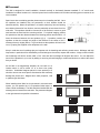
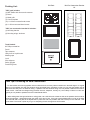
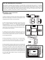
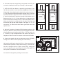
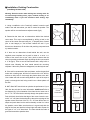
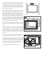
® iW4 In-Wall Loudspeaker OWNER’S MANUAL Now Hear This 6400 Goodyear Road Benicia, CA 94510 800-NHT-9993 Thank you for your purchase of the NHT iW4 in-wall loudspeaker. Please take a few minutes to read through this Owner's Manual prior to installing your new speakers. The information provided will help you to obtain maximum performance from your audio system. If you have questions or need assistance at any time during the installation or operation of your new speakers, please call your NHT Dealer or our Toll-Free Customer Hotline at: 1-800-NHT-9993 iW4 Specifications · System Type: 3-way in-wall design · Driver Complement: (2) 5.25" long-throw polypropylene woofers, 2” aluminum dome midrange, 3/4" aluminum dome tweeter · Crossover: 750Hz, 18dB/octave and 5KHz 18dB/octave · Response: 50Hz - 20KHz, +/-3dB · Sensitivity: 86dB (2.83V at 1M) · Impedance: 8 ohms, min. 5.5 ohms. · Recommended Amplifier Power: 20w/ch. min., 150w/ch. max. · Inputs: Professional grade spring posts · Weight: 10 lbs. each · Dimensions: Cutout 13.56" x 9"; Bezel 14.7" x 10.1"; from front of wall to back of speaker: 3.19” · Finish: Matte white (paintable) Specifications are subject to change without notice, in accordance with our policy of continuously upgrading the performance of our products. Design NHT loudspeakers are designed to deliver refined, musical sound from attractive and affordable packages. Our efforts are guided by the study of human hearing and are optimized for real-world use. Every NHT speaker undergoes rigorous testing and quality control at the factory to ensure you years of listening pleasure. The NHT iW4's custom-designed drive units are mounted in a rigid baffle/bezel assembly designed to minimize the audible effects of unwanted vibrations and resonance. The baffle is 18mm MDF, the same material used in high quality box speakers. It is separated from the bezel by absorptive materials designed to prevent the coloration of critical midrange frequencies caused by wall vibration. The mounting assembly is designed to be intuitive and flexible, making it ideal for new or existing construction. With high performance sonics and a paintable grille and frame, the iW4 is the perfect solution for architectural audio and home theater installations. Caution: The iW4 should be installed by an experienced and licensed custom installation professional. Be sure that the installer possesses sufficient skill, the proper tools, knowledge of local fire and building codes, and a familiarity with the structure of the building (especially wall and/or ceiling materials, layouts, electrical and plumbing lines, etc.). Placement The iW4 is designed for in-wall installation, oriented vertically or horizontally between standard 2" x 4" wood studs. Installation in outdoor locations or in moisture-prone interior environments such as indoor swimming pools or saunas is not recommended. Spend some time considering speaker placement prior to installing the iW4. Once the speakers are installed, they are permanent, so their location should be selected carefully. Mount the speakers in a location where they face the listening area without obstruction from furniture, and are preferably at least three feet from side walls. The speakers should be mounted on a flat surface to ensure a good seal between the bezel and the mounting surface. For optimal imaging, position the speakers so that the distance between the listening position and the wall is 1.5 times the distance between the two speakers (fig.1). If possible, position the speakers so that the average ear height of the listeners is the center of the 2” midrange dome (or slightly below). To get an idea how the speakers will look in the room, try taping the supplied cutout templates to the wall. fig.1 Keep in mind that room furnishings play an important role in absorbing and reflecting sound waves. Midrange and high frequencies in particular will be absorbed by soft furnishings such as sofas, carpets and curtains. A large number of these soft furnishings will dull the sound, while a "live" room with few furnishings will brighten the sound. You can adjust the sound of the speakers in your room by adding or removing soft wall hangings, curtains and furniture to achieve the sound that you desire. As the iW4 is not magnetically shielded, do not install it in a location where it will be within 12" of a direct view (tube) television. Unshielded magnets placed in close proximity to a television screen can cause picture discoloration and eventually damage the picture tube. Magnets don’t effect projection, LCD or plasma type televisions. When installing three iW4's for front channels in a home theater system, you can position the L & R speakers farther apart to create a wider soundstage. The iW4 should be installed with the midrange dome closest to the television. The placement diagram to the right shows three possible orientations. Packing List: iW4 Pack iW4 Pre Construction Bracket Kit "iW4" pack includes: (1) MDF Baffle with drivers and crossover (1) Bezel (1) Metal grille (1) Cutout template (12) 4 x 20mm recessed head screws (8) 4 x 50mm recessed head screws "iW4" pre construction bracket kit includes: (1) Mounting bracket (2) Mounting wings, aluminum Tools Needed: #2 Philips screwdriver Pencil Tape measure Utility knife or keyhole saw Masking tape Level Wire strippers Safety goggles Protective gloves Tech Tips: Pre-Wiring for New Construction 1. For best results, avoid running speaker wire near electrical wire, as it may induce a 60Hz hum in the audio signal. It’s a good idea to run the speaker wire after the electrical wiring has already been completed, so that you can route the speaker wire at least three feet away from the electrical wiring. If speaker wire and electrical wiring must run parallel, install the wire within a metal conduit. Note that low-voltage wiring (doorbell, intercom, telephone, security, etc.) are unlikely to induce hum and can typically be run parallel to speaker wire with no detrimental effects. 2. When drilling holes through wall studs or ceiling joists, use a drill bit that is at least as wide as the speaker wire that will be routed through them. Always drill through the center of the stud or joist. If the hole must be drilled within one inch of the edge of a wall stud, add a nail plate to the drywall side to protect the wire from possible nails and screws put in the wall later. Line up the holes in the studs or joists as you go, so that pulling the wire through them will be easier. Tech Tips: Optimizing Sonic Performance Bass response is smoothest when the speaker is mounted within a rigid wall that flexes very little. For improved performance, add 2"x4" cross-braces horizontally roughly 15 inches above and below the speaker location. Use wood glue and extra screws when attaching the drywall to the studs around the speaker. Additionally, once the speaker cutout has been made in the drywall, add a bead of wood glue inside the wall where the drywall meets the studs and cross-braces. If possible, use two layers of drywall for maximum rigidity. Installation: New Construction (unfinished walls) fig.2 8 7 6 6 7 9 5 4 5 8 9 01 3 4 10 11 2 3 11 21 2 31 1 1 2 3 4 5 6 7 8 9 10 11 12 13 14 1 12 41 1 2 3 4 5 6 7 8 9 10 11 12 13 14 13 14 1. Begin by installing the mounting bracket between adjacent studs. Attach the mounting wings to the bracket by inserting them into the locking plastic tabs in the side of the bracket (fig.2). 2. Select the desired location for the speaker, using a level to ensure that it is precisely positioned. The wings feature progressively elongated sections (1", 1", 2", 2", 2", 3", 3") with screw holes spaced in one-inch increments. Attach the wings to the studs with screws or staples. Break off the extra portion of the wing by bending it at one of the pre-stamped "break" lines (fig.3). Break 8 9 10 11 12 13 14 3. Complete the pre-wiring before the drywall goes up (see "Tech Tips: Pre-Wiring for New Construction" on the previous page). Leave an extra few feet of speaker cable, and secure it to the cable tie on the mounting bracket (fig.4). 7 7 8 6 6 9 5 5 01 4 4 11 3 3 21 1 2 3 1 2 1 2 3 fig.3 2 2 31 2 Break 1 1 2 3 4 5 6 7 8 9 10 11 12 13 14 1 41 1 1 2 3 4 5 6 7 8 9 10 11 12 13 14 Break Break 4. During the drywall phase, cut a hole 13 9/16" x 9" around the brackCable Tie et. The bezel outer frame will extend out about 1 inch beyond the perimeter of the cutout to hide minor imperfections in the cutout. fig.4 3 3 4 2 2 4 5 1 1 5 5. After the drywall is complete, attach the bezel to the bracket with (8) 4 x 50mm recessed head screws that line up with the 8 raised bosses on the bracket (fig.5). Tighten screws snugly, making sure not to over-tighten, as this may compromise the fit of the bezel. The use of power screwdrivers is not recommended. The absorptive strip on the back of the bezel's outer frame reduces unwanted vibrations and will compress slightly to allow the frame to rest flush against the wall on all four sides. When installed correctly, the bracket and bezel "sandwich" the drywall. 1 2 3 1 2 3 1 fig.5 1 6. If the iW4 bezel frame and grille are to be painted in the wall, paint now before installing the baffle (see "Painting" on the last page). Foam Foam Foam Foam 2 - 3 inches 4 - 5 inches Stud Foam Foam Foam Foam Stud Cutout Vertical Stud Cutout Horizontal Stud 7. NHT offers iWF foam blocks to optimize the performance if your iW4. See the web site for more information: nhthifi.com Refer to the diagram (fig. 6) for orientation of the foam blocks. Insert one of the 4" x 4" x 8" foam blocks vertically through the speaker cutout. Push this block down below the edge of the cutout. Insert the second 4" x 4" x 8" foam block and push up above the top edge of the speaker cutout. Bend one of the 4" x 4" x 16" foam blocks into a U shape and push down into the wall horizontally so that it is below the speaker cutout. Make sure that there is a good seal with the edge of the foam and both the left and right wall studs. Repeat for the upper 4" x 4" x 16" foam block. The foam should also make a good seal around the speaker wires. fig.6 8. Add a 26" long piece of unbacked R19 fiberglass insulation to the enclosure. (Be sure to wear protective gloves and goggles when handling fiberglass to avoid contact with the fiber). You may need to cut a 11" wide by 7" high rectangular hole in the center of the piece of fiberglass to make room for the crossover on the back of the baffle. fig.7 9. Connect the speaker wire to the spring posts on the iW4 baffle, making sure to observe correct polarity (see "Connections"). 3 4 11. Attach the metal grille by inserting it into the bezel. 2 2 10. Attach the baffle to the bezel with (12) 4 x 20mm recessed head screws that line up with the 12 holes in the bezel (fig.7). Exercise caution not to damage the drivers. Tighten screws snugly, making sure not to over-tighten, as this may compromise the fit of the baffle. The use of power screwdrivers is not recommended. 3 1 1 2 1 4 1 2 Installation: Existing Construction (retrofitting finished walls) Warning: Exercise caution when drilling into existing walls. Do not drill through existing wires, pipes, conduits, heating or air conditioning ducts. If you feel resistance while drilling, stop immediately. fig.8 Cutout Horizontal 1. Using a studfinder or the "knocking" method, locate the wall studs in the wall area where you wish to mount the speaker. The speaker will be mounted between adjacent studs (fig.8). Cutout Vertical Cut Cut Drill Stud Stud Drill Stud Stud 2. Determine that there are no obstructions behind the desired cutout area. This may be accomplished by drilling a hole in the center of the cutout area and using an "L"-shaped piece of metal (like a coat hanger) to "feel around" behind the wall. If you discover an obstruction, fill the hole with patching compound and try another location. 3. If there are no obstructions found behind the wall, use the supplied cutout template and a pencil to draw a 13 9/16" x 9" outline of the area to be cut out. Use a level to ensure that the cutout is precisely positioned. Begin by drilling the four corners with a ¼" bit (fig.8). Then cut out the wall section with a utility knife or keyhole saw, following the lines traced around the mounting template. If the wall is painted or wallpapered, use the keyhole saw. 4. If the wall is constructed of lath and plaster, outline the penciled marks with masking tape, drill the four corners with a 1/4" drill bit, and use a utility knife to cut through the plaster down to the lath. Use a saber saw with a metal cutting blade or a pair of tin snips to gently cut through the lath, being careful not to vibrate plaster off the wall. Foam Foam Foam Foam 2 - 3 inches 4 - 5 inches Stud Foam Foam Foam Foam Stud Cutout Vertical Stud Cutout Horizontal Stud 5. NHT offers iWF foam blocks to optimize the performance if your iW4. See the web site for more information: nhthifi.com Refer to the diagram (fig. 9) for orientation of the foam blocks. Insert one of the 4" x 4" x 8" foam blocks vertically through the speaker cutout. Push this block down below the edge of the cutout. Insert the second 4" x 4" x 8" foam block and push up above the top edge of the speaker cutout. Bend one of the 4" x 4" x 16" foam blocks into a U shape and push down into the wall horizontally so that it is below the speaker cutout. Make sure that there is a good seal with the edge of the foam and both the left and right wall studs. Repeat for the upper 4" x 4" x 16" foam block. The foam should also make a good seal around the speaker wires. fig.9 6. Insert the iW4 mounting bracket diagonally through the cutout in the wall, then pull forward into position. If the cutout was cut correctly according to the cutout template, the bracket should fit snugly into place. The plastic tabs on all sides of the bracket will rest against the rear side of the wall (fig.10). If the tabs interfere with a stud, break them off with pliers. fig.10 7. While holding the bracket flat against the rear side of the wall with one hand, attach the bezel to the bracket with (8) 4 x 50mm recessed head screws that line up with the 8 raised bosses on the bracket (fig. 11). Tighten screws snugly, making sure not to overtighten, as this may compromise the fit of the bezel. The use of power screwdrivers is not recommended. The absorptive strip on the back of the bezel's outer frame reduces unwanted vibrations against the drywall, and will compress slightly to allow the frame to rest flush against the wall on all four sides. When installed correctly, the bracket and bezel "sandwich" the drywall. fig.11 2 2 3 4 8. If the iW4 bezel frame and grille are to be painted in the wall, paint now before installing the baffle (see "Painting" on the next page). 3 1 1 1 4 1 9. Add a 26" long piece of unbacked R19 fiberglass insulation to the enclosure. (Be sure to wear protective gloves and goggles when handling fiberglass to avoid contact with the fiber). You may need to cut a 11" wide by 7" high rectangular hole in the center of the piece of fiberglass to make room for the crossover on the back of the baffle. 10. Connect the speaker wire to the spring posts on the iW4 baffle, making sure to observe correct polarity (see "Connections"). 3 2 1 2 3 4 12. Attach the metal grille by inserting it into the bezel. 4 1 11. Attach the baffle to the bezel with (12) 4 x 20mm recessed head screws that line up with the 12 holes in the bezel (fig. 12). Exercise caution not to damage the drivers. Tighten screws snugly, making sure not to over-tighten, as this may compromise the fit of the baffle. The use of power screwdrivers is not recommended. fig.12 Painting The bezel frame and grille of the iW4 are finished in a matte white powder-coated finish that may be painted to match the wall. Keep in mind that the grille contains hundreds of tiny holes that are essential to the sound of the speaker. Take care not to cover these holes with paint. 1. Paint the bezel frame and the grille at the same time using the same paint. Do not install the fiberglass sheet in the space formed by the acoustic foam because overspray from painting will reduce its effectiveness. We do not recommend painting while the baffle with the drivers is installed. The baffle itself is paintable if you remove the drivers; however, the black finish of the baffle prevents the speaker's black drive units from being visible once the grille is in place. 2. When using spray paint, apply two thin coats, making sure to let the first coat dry completely before applying the second. This will avoid running. When using a compressor and spray gun, apply the paint using its finest setting. Painting with a brush is not recommended, but when necessary be sure to thin the paint so as not to cover the holes in the grille. If paint does cover any of the grille holes, poke them out with a paper clip. Connections Before connecting speakers to your system, it is important that you turn off the power to your amplifier / receiver to avoid damage to the equipment. Before installing the iW4, map out the wiring paths between the speakers and the amplifier. Make sure that the speaker wire does not rest on sharp or pointed objects. The iW4 is compatible with virtually all quality amplifiers. Proper wiring of the speakers is essential to good sound. At a minimum, 16AWG 2-conductor speaker wire is recommended for runs of 10 feet or less, with larger gauge special purpose speaker wire suggested for longer runs. For best results, use equal length runs of wire for all speakers. When permanently installing wire inside walls, be sure to use wire that is rated for in-wall use and has special jacketing for fire prevention. In the U.S., the U.L. standard is CL-2, CL-3 and CM wire, and in Canada the CSA standard is FT4 wire. The wires should be run in accordance with National Electrical Code and any applicable local building codes. Prepare the wire by stripping 1/4" to 3/8" of insulation from the ends and twisting the exposed wire strands tightly. The spring-loaded binding posts on the back of the speaker will accept raw wire only. Be sure to wire both the left and right speakers "in-phase." That is, the Positive (red) terminal on the amplifier output must be connected to the corresponding Positive (red) terminal on the speaker. Likewise with the Negative (black) terminals. All speaker wire have some sort of marking along one or both conductors to help you make the correct connections. Incorrect speaker phase is indicated by weak bass and the lack of a well-defined stereo image. Operation The iW4 was designed to handle a wide range of listening levels, but every speaker has limits. It is important to use common sense and listen for signs of possible distress from the speakers. Underpowered amplifiers are most often the cause of speaker damage. For example, a 60-watt amplifier runs out of power when called upon to produce more than 60 watts, and the resulting distortion can damage the speaker. If you tend to listen at high volume levels, more powerful amplifiers are preferable because they are less likely to run out of power. Noticeable distortion or harsh breakup is an indication that either your amplifier or your speakers are running beyond their capacity, and the volume should be decreased. If you can feel any heat emanating from the woofers or tweeter, reduce the level immediately. Speaker damage most often occurs from sustained high volume levels, not from transient sounds or brief musical peaks. Excessive boosting of bass, treble or equalizer controls can worsen the problem, and is not recommended. Maintenance The iW4's require minimal maintenance under normal use. The grille and frame may be cleaned using a damp cloth or a mild, non-abrasive cleaner. Do not expose the speaker to direct sunlight, high temperatures, or moisture. Do not attempt to clean the actual drivers. Limited Warranty Valid Only in the U.S.A. and Canada Warranty Period For the period of 5 years for parts and 5 years for labor from date of original purchase (the warranty period) from an authorized NHT dealer, Now Hear This (NHT) warrants that if our product fails to function properly under normal use due to a manufacturing defect when installed and operated according to the owner’s manual instructions enclosed with the unit, it will be repaired or replaced with a unit of comparable value at the option of NHT without charge to you for parts or actual repair work. Parts supplied under this warranty may be new or rebuilt at the option of NHT. What’s Not Covered This warranty does not cover any product which is used in any trade or business, or in an industrial or commercial application. This warranty does not cover the cabinet or any appearance item, or any damage caused to the product resulting from: alterations, modifications not authorized in writing by NHT, accident, misuse or abuse, damage due to lightning or power surges, or being subjected to power in excess of the speaker’s published power rating. This warranty does not cover the cost of parts which would otherwise be provided without charge under this warranty, obtained from any source other than an authorized NHT service location. This warranty does not cover defects or damage caused by the use of unauthorized parts or labor or from improper maintenance. Altered, defaced or removed serial numbers void this warranty. Your Rights The liability of NHT will be limited to the purchase price of the product, and NHT will not be liable for incidental or consequential damages. NHT limits its obligations under any implied warranties under state laws to a period not exceeding the warranty period. Some states do not allow limitations on how long an implied warranty lasts, and some states do not allow the exclusion or limitation of incidental or consequential damages. The above limitations or exclusions may not apply to you. This warranty gives you specific legal rights, and you may have other rights which vary from state to state. To Obtain Service NHT has appointed a number of authorized service companies throughout the USA should your product ever require service. To receive warranty service, you will need to present your sales receipt showing place and date of original owner’s transaction. To find the name and address of the nearest authorized NHT service location, call or write: Customer Service Department, Now Hear This, 6400 Goodyear Road, Benicia, CA 94510. 800-NHT-9993. Please do not return product to this address. It is not a service location. Keep this warranty with your sales receipt. Record date and place of purchase for future reference.