1
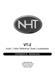
X2
Active Crossover
OWNER’S MANUAL
Now Hear This
6400 Goodyear Road
Benicia, CA 94510
800-NHT-9993
Specifications
X2
Active Crossover
Frequency response: 15Hz - 220Hz +/-3dB
through L/R input (continuously variable)
15 - 220Hz +/-3dB through LFE input (fixed)
50, 80, 110Hz-100KHz +/-3dB
Distortion: < 0.01% subwoofer output @ 100Hz, 1V
< 0.001% hi-pass output @ 1KHz, 1V
Signal to noise ratio: >105dB at Hi-pass output
>100dB at subwoofer output
Crossover: Low-pass continuously variable between 30-220Hz, 12dB/octave
Low-pass fixed at 220Hz,12dB/octave
High-pass selectable between 50, 80, 110Hz, 12dB/octave
Input connectors:
Gold plated RCA jacks for L and R line level input
XLR jacks for L and R line level input
Gold plated RCA jack for LFE input
XLR jack for LFE input
Detachable terminal block for external trigger in/thru
2.1mm x 5.5mm x 9.5mm power connector
Output connectors:
Gold plated RCA jacks for L and R line level high-pass output
Gold plated RCA jack for LFE thru
XLR jacks for L and R line level high-pass output
Gold plated RCA jacks for L and R line level sub woofer output
XLR jacks for L and R line level subwoofer output
Phase Control:
Variable between 0 and 90 degrees
Switchable 0 - 180 degrees
Gain Control: +10dB and 0dB subwoofer input sensitivity
Stereo / Mono Switch: Stereo or mono subwoofer operation
Standby Mode: Selectable internal and external. External 5 -24 VDC
Internal automatic when no signal is present for >20 minutes
Power Consumption: 3W
Weight: 9 lbs.
Dimensions: 1.5"H x 17"W x 11.5"D
Finish: matte black anodized front panel, black painted chassis
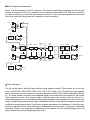
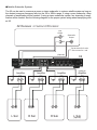
Block Diagram and Schematic
Below is a block diagram of the X2 crossover. This may be useful when integrating the X2 into your
system. A schematic of the X2 is available on our website at www.nhthifi.com. This may be useful if
you wish to modify any of the filter characteristics in the X2. This is only recommended for users with
the correct technical training and will completely void your warranty.
LFE in
LFE
Gain
LFE out
50, 80, 110
Hz
L
HP out
HPF
30-220Hz
L in
Phase
0-180
Phase
Master Gain
Gain 0, 10dB
HPF
20 Hz
0-90
Sub Out
L
LPF
Mono
30-220Hz
Boundary
Stereo
0-180
200 Hz
-6
LPF
R in
Boundary
6
200 Hz
6
0-90
Sub Out
R
-6
LPF
Phase
Phase
Master Gain
Gain 0, 10dB
20 Hz
HPF
LPF
50, 80, 110
Hz
L
HP out
HPF
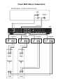
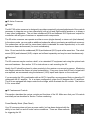
Tower Speakers
The X2 can be used to biamplify many different tower speaker models. This includes, but is not limited to, the NHT M3.3, M2.9, M2.5, M2.5i, VT2, VT2.4, VT1.2 and VT1.4. Basically any tower speaker
with a subwoofer to woofer crossover frequency between 50 and 200Hz can be biamplified with the
X2. The tower speaker must also have separate inputs for the subwoofer (low frequency) and woofer
(high frequency) section. Any jumper straps connecting these two sections must be removed, or
severe damage may occur to the amplifers driving the speakers. Tower speakers that do not have separate low and high frequency inputs may be biamplified with the X2 provided the speaker crossover is
modified to have separate inputs. Consult your speaker manufacturer for assistance. If driving the subwoofers in parallel (mono), three channels of amplification will be needed. If driving the subwoofers
separately (stereo), four channels of amplification will be needed. See the following diagrams for the
proper system wiring when biamplifying with an X2.
Tower With Stereo Subwoofers
AV Receiver or Surround Processor
Line
Output
L
Subwoofer
Output
R
(Optional)
X2
Amplifier
Amplifier
Speaker
Outputs
Line
Input
-
+
Line
Input
-
+
-
+
High
Tower
L
Tower
R
+
-
Low
+
Low
Amplifier
Speaker
Outputs
-
+
Line
Input
High
-
Amplifier
Speaker
Outputs
Speaker
Outputs
-
+
Line
Input
+
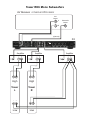
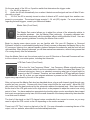
Tower With Mono Subwoofers
AV Receiver or Surround Processor
Line
Output
Subwoofer
Output
L
R
(Optional)
X2
Amplifier
Amplifier
Speaker
Outputs
Line
Input
-
+
Line
Input
-
+
-
+
High
Tower
L
Tower
R
+
-
Low
Speaker
Outputs
-
+
Line
Input
High
-
Amplifier
Speaker
Outputs
+
Low
+
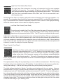
Satellite Subwoofer Systems
The X2 can be used to crossover a mono or stereo subwoofer to a stereo satellite system as long as
the desired crossover frequency falls into the 50 to 200Hz range. If using a mono subwoofer, three
channels of amplification will be needed. If using a stereo subwoofer system, four channels of amplification will be needed. See the following diagram for the proper system wiring when biamplifying with
an X2.
AV Receiver or Surround Processor
Line
Output
L
Subwoofer
Output
R
Set to stereo for 2 subs
Set to mono for 1 sub
(Optional)
X2
(Optional)
Amplifier
Amplifier
Speaker
Outputs
Line
Input
-
+
Line
Input
-
+
L Sat
Amplifier
Speaker
Outputs
-
-
+
Line
Input
+
R Sat
Amplifier
Speaker
Outputs
Speaker
Outputs
-
+
Line
Input
-
+
R Sub
-
+
L Sub
(Optional)
+
X2 Active Crossover
Design
The NHT X2 active crossover is designed to provide convenient front-panel adjustment of the controls
necessary to integrate one or two subwoofer(s) with a Left and Right satellite speaker or to biamp a
3-way tower loudspeaker. The unit has unbalanced RCA and balanced XLR inputs and outputs for
connection with all types of receivers or separate audio components.
The X2 active crossover can operate as either a mono (single channel) or stereo unit (dual channel).
In the stereo mode, you may add an additional subwoofer without purchasing an additional crossover.
Two subwoofers can be used for stereo bass (which is desirable for music reproduction) or for additional mono bass reinforcement (for movie soundtracks).
Note: Do not use both the unbalanced (RCA) and balanced (XLR) inputs at the same time. The unbalanced (RCA) and balanced (XLR) outputs are buffered separately and may be used simultaneously.
Placement
The X2 crossover may be used on a shelf, or in a standard 19" equipment rack using the optional rack
ears and hardware. See section 10.3 for instructions on rack mounting the X2.
Ideally, the X2 should be placed in close proximity to the receiver or surround processor. Minimizing
wire lengths reduces the chance of noise contamination. If long runs (more than 20 feet) of signal wire
are required, we recommend using the balanced (XLR) inputs and outputs on the crossover.
If you are using the X2 in combination with an NHT A1 amplifier, we recommend that you place the X2
underneath the A1 amplifier. Or, in a stereo configuration, place the X2 between two A1 amplifiers.
The A1's are equipped with lamps under the front edge, which illuminate the X2 controls. See section
9.2 for more detail.
X2 Features and Controls
This section describes the various controls and functions of the X2. Make sure that your X2 controls
are initially set as described in Section 7 before continuing.
Power/Standby Mode (Rear Panel)
Your X2 crossover does not have a power switch, but has been designed with the
ability to turn itself on and off under various conditions. There are three methods
for triggering the X2.
On the rear panel of the X2 is a 3-position switch that determines the trigger mode:
1)
On; the X2 is always on.
2)
Audio; the X2 will automatically turn on when it detects an audio signal and turn off after 20 minutes with no signal.
3)
12V Ext; the X2 is remotely turned on when it detects a DC control signal from another component in your system. The external trigger accepts 5 - 24 volt (DC) signals. For more information
regarding external triggers, consult your authorized dealer.
Master Gain (Front Panel)
The Master Gain control allows you to adjust the volume of the subwoofer relative to
the satellite speakers. Use the Master Gain judiciously. A properly calibrated subwoofer blends seamlessly with the satellites without calling attention to itself. Here are
some general guidelines for setting the Master Gain control:
Begin by playing some stereo music you are familiar with. Set your AV Receiver or Surround
Processor volume to a comfortable listening level. Slowly increase or decrease the Master Gain on the
X2 crossover, listening for a natural frequency balance between the subwoofer and the front left and
right satellites. When properly balanced, you will hear natural bass extension, without being aware that
it is coming directly from the subwoofer.
Once the Master Gain is set, the volume control on your AV Receiver or Surround Processor will control the volume of your entire system, including the subwoofer.
LFE Gain Control (Front Panel)
LFE is short for 'Low Frequency Effects'. Low Frequency Effects originally were low
frequency sounds added to movie soundtracks in order to increase their impact. For
consumer electronics, there is no standard concerning what type of signal might be
present on the LFE channel. Therefore, we have added an LFE input and gain control
to the X2 so that you can integrate whatever is present on the LFE channel with the
signal being reproduced by the rest of the system.
After you have set the Master Gain level as described above, play a multi-channel signal through your
system (as from a movie). Sources with lots of bass output will be the most useful. Adjust the LFE
gain control until the bass produced by the subwoofer reaches the desired level. Most users initially
set the level of the LFE gain control at too high a level, so be prepared to adjust the control over a long
period of time. You have reached an appropriate level setting when movies soundtracks have impact
and music sources have punchy bass, but the overall character of the bass produced by the subwoofer
is not thick and ill defined.
The level of the signal on the LFE channel varies considerably from source to source, so you may
need to adjust the LFE control on the X2 depending on the source material.
There is an LFE "Thru" output on the back of the X2. For more information concerning the use of this
output, visit our website, www.nhthifi.com/technicalhelp/evolution .
High Pass Filter Switch (Rear Panel)
The High Pass Filter determines the range of frequencies that the main speakers
("satellites") will reproduce. For example, a high pass setting of 80Hz means that the
main speakers receive a signal containing only frequencies above 80Hz. The 3-positon
High Pass Filter is selectable between 50Hz, 80Hz, and 110Hz to accommodate a variety of speaker sizes.
Set the High Pass Filter to a frequency above the rated low frequency limit of the main speakers. For
example, if your speakers have a rated low frequency response of 40Hz, use the 50Hz high-pass setting. If your speakers have a rated low frequency response of 90Hz, use the 110Hz high-pass setting.
Check the owner's manual for their rated low frequency response.
Low Pass Filter Control (Front Panel)
The continuously variable Low Pass Filter determines the range of frequencies produced
by the subwoofer. For example, a low pass setting of 100Hz means that the subwoofer
reproduces only frequencies below 100Hz. The LFE input is not affected by this control.
Adjust the Low Pass Filter to approximately the same setting as the High Pass Filter as a starting point.
Adjust the Low Pass Filter in small increments up or down until the blend between the subwoofer and
your main speakers is seamless and the subwoofer does not call attention to itself. Music featuring
male vocals, cello and acoustic bass, bass guitar and certain wind instruments (like saxophone and
trombone) is useful for setting the low pass frequency.
Phase Controls (Front Panel)
The Subwoofer Phase switch and continuously variable knob change the phase of the
subwoofer output anywhere from 0° to 270° relative to the high pass output. Proper
subwoofer phase is important to achieve smooth bass response. An improper phase
setting causes dips in the frequency response of the combined subwoofer/satellite
system at the listening position. The result of these dips is low frequency production
that is very deficient at certain frequencies and a lack of seamless integration between the satellites
and subwoofer.
The optimal phase setting will vary depending on room conditions and placement. While fine tuning
the phase setting, have a familiar stereo CD available. You should listen to the same song while alternating phase settings. Find the best setting while sitting at the primary listening position.
The initial settings described in Section 7 provide a good starting point for your system. However,
experimentation is the key to getting the best possible sound quality out of the system. Begin by setting the phase knob at 0°, alternating the switch position between 0° and 180°. From the listening position, choose the switch position that yields the most bass output and leave the switch in that position.
Then use the knob to fine-tune the phase setting. Slowly twist the knob, listening for the point at which
the bass at the listening position is the loudest. Small changes in phase generally produce subtle
changes in bass output. You may have to adjust the knob now and again over a period of a few weeks
to find the best setting for your listening room.
Gain Switch (Rear Panel)
The Subwoofer Gain switch allows you to increase the gain of the X2 subwoofer output
by 10dB. Normally, the factory default "0" position will give you a wide range of volume
adjustment. However, if the sensitivity of your satellite speakers is greater than 93dB,
your range of volume adjustment on the X2 may be limited. In this case, set the Gain
Switch to 10dB.
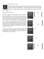
Boundary EQ (Front Panel)
Reflective boundaries (such as walls) reinforce a speaker's
bass output (3dB for two walls, 6dB for a corner) if the subwoofer is placed near them. Conversely, placing a subwoofer
out in the room results in a relative decrease in bass output.
Boundary reinforcement may lead to low frequency response
that is uneven. Some frequencies will sound exaggerated relative to others, or the subwoofer will sound thin and lack
impact. The Boundary EQ control allows you to compensate
for the effects of room boundaries on the frequency response
of the subwoofer. Adjusting the control enables you to achieve
smooth low frequency output from the subwoofer regardless of
its location in your room.
The following diagrams show the correlation between subwoofer placement and Boundary EQ. These diagrams are
guidelines only. Your room acoustics and personal tastes will
ultimately dictate the final setting.
System Status Indicators (Front Panel)
Located on the right hand side of the front panel are two LEDs. They are used to indicate the functional status of the X2 Crossover.
P - Power LED (green) - indicates the X2 is on and in a ready condition.
S - Standby LED (amber) - indicates the X2 crossover is in "standby" mode.
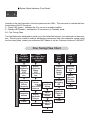
8.5 Fine Tuning Chart
The chart below was developed to assist you in the further fine tuning of your subwoofer or tower system. Should you be unable to achieve satisfactory performance from your subwoofer system using
the fine-tuning chart, contact your authorized NHT dealer or call our Customer Hotline at 1-800-NHT-
Problem
"Boomy"
Too Much
Mid / Upper
Bass
Lacks
Mid / Upper Bass:
Lean But With
Weight
Solution
Fine Tuning Flow Chart
Adjust
Subwoofer
Phase
0-90
Adjust
Subwoofer
Phase
0-90
(Continuously
Add)
(Continuously
Add)
Lower
Low Pass
X-Over
Frequency
If this makes
it worse,
try
If the sound
improves
Lower
Subwoofer
Volume
Adjust
Subwoofer
Volume
Listen
Listen
Raise
Low-Pass
Setting
Adjust
Subwoofer
Volume
Adjust
Subwoofer
Phase
Listen
Lacks
Low
Bass
Weight
Excessive
Low
Bass
Weight
Adjust
Subwoofer
Phase
Switch
0-180
Decrease
Boundary
EQ
Increase
Boundary
EQ
Move
Subwoofer
Farther
From Wall
Listen
Move
Subwoofer
Closer to
Wall
Listen
Limited Warranty
Valid Only in the U.S.A.
Warranty Period
For the period of 5 years for parts and 5 years for labor from date of original purchase (the warranty period) from an authorized NHT dealer, Now Hear This (NHT) warrants that if our product fails to function properly under normal use due to a manufacturing defect when installed and operated according to the owner’s manual instructions enclosed with the unit, it will be
repaired or replaced with a unit of comparable value at the option of NHT without charge to you for parts or actual repair work.
Parts supplied under this warranty may be new or rebuilt at the option of NHT.
What’s Not Covered
This warranty does not cover any product which is used in any trade or business, or in an industrial or commercial application.
This warranty does not cover the cabinet or any appearance item, or any damage caused to the product resulting from: alterations, modifications not authorized in writing by NHT, accident, misuse or abuse, damage due to lightning or power surges,
or being subjected to power in excess of the speaker’s published power rating.
This warranty does not cover the cost of parts which would otherwise be provided without charge under this warranty, obtained
from any source other than an authorized NHT service location. This warranty does not cover defects or damage caused by
the use of unauthorized parts or labor or from improper maintenance.
Altered, defaced or removed serial numbers void this warranty.
Your Rights
The liability of NHT will be limited to the purchase price of the product, and NHT will not be liable for incidental or consequential
damages. NHT limits its obligations under any implied warranties under state laws to a period not exceeding the warranty
period. Some states do not allow limitations on how long an implied warranty lasts, and some states do not allow the exclusion or limitation of incidental or consequential damages. The above limitations or exclusions may not apply to you. This warranty gives you specific legal rights, and you may have other rights which vary from state to state.
To Obtain Service
NHT has appointed a number of authorized service companies throughout the USA should your product ever require service.
To receive warranty service, you will need to present your sales receipt showing place and date of original owner’s transaction.
To find the name and address of the nearest authorized NHT service location, call or write: Customer Service Department,
NHT, 6400 Goodyear Rd., Benicia, CA 94510, 1-800-NHT-9993 (648-9993), www.nhthifi.com
Keep this warranty with your sales receipt. Record date and place of purchase for future reference.