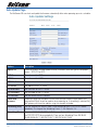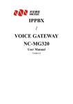
1
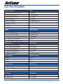
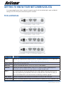
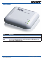
User Guide
V110, V210P, V211, V220
VoIP ATA
Welcome to the Wonderful World of VoIP
Congratulations on your purchase of a NetComm VoIP ATA. Whether this is your first VoIP device or you
are upgrading from another device we’re glad to have you as part of the NetComm family. The NetComm
V110/V210P/V211/V220 ATA’s are true next generation technology and in addition to the fantastic savings
you’re going to experience you’ll also get fantastic features such as routing, T.38 Fax and 3 way conferencing.
This Quick Start Guide contains everything you need to get you up and running for everyday use but if
you need to delve into any of the more advance configuration features available on your unit you’ll find a
comprehensive User Guide on the CD that accompanies the ATA.
Should you run into any problems with your unit (and let’s face it, we all need a little help from time to time)
you can find the answers to many questions in the support section of our website
www.netcomm.com.au/Support/
So without any further delay it’s time to get you more familiar with your ATA so you can start using VoIP.
IMPORTANT NOTICE: Please ensure that the Broadband modem/router to be used with this ATA has been designed to handle VoIP traffic. Most new
broadband modem/router will be able to handle VoIP without any issues and do not need extra configuration to handle VoIP service. However, old
broadband modem/router might need to be configured correctly to support it.
Please check with the broadband modem/router manufacturers for more details.
YML881Rev1
www.netcomm.com.au
������
V110, V210P, V211, V220
������� ������ ���� User Guide
VoIP ATA Features
Network Protocol
Tone
• SIP v1 (RFC2543), v2(RFC3261)
• Ring Tone
• IP/TCP/UDP/RTP/RTCP
• Ring Back Tone
• IP/ICMP/ARP/RARP/SNTP
• Dial Tone
• TFTP Client/DHCP
• Busy Tone
• Client/ PPPoE Client
• Programming Tone
• Telnet/HTTP Server
• DNS Client
• NAT/DHCP Server
Codec
Phone Function
• G.711: 64k bit/s (PCM)
• Volume Adjustment
• G.723.1: 6.3k / 5.3k bit/s
• Speed dial key
• G.726: 16k / 24k / 32k / 40k bit/s (ADPCM)
• Phone book
• G.729A: 8k bit/s (CS-ACELP)
• Flash
• G.729B: adds VAD & CNG to G.729
Voice Quality
Call Function
• VAD: Voice activity detection
• Call Hold
• CNG: Comfort noise generator
• Call Waiting
• LEC: Line echo canceller
• Call Forward
• Packet Loss Compensation
• Caller ID
• Adaptive Jitter Buffer
• 3-way conference
IP Assignment
Auto Provisioning
• Static IP
• HTTP
• DHCP
• FTP
• PPPoE
• TFTP
DTMF Function
NAT Traversal
• In-Band DTMF
• STUN
• Out-of Band DTMF
• SIP Info
SIP Server
Configuration
• Registrar Server
• Web Browser
• Outbound Proxy
• IVR/Keypad
V110, V210P, V211, V220 User Guide
YML881Rev1
www.netcomm.com.au
Firmware Upgrade
Security
• TFTP
• HTTP 1.1 basic/digest authentication for Web setup
• HTTP
• MD5 for SIP authentication (RFC2069/ RFC 2617)
Interface
Modem & Fax modes
1 WAN port interface
• G.711 fax/modem pass-through with fax/modem detection
1 LAN port interface
• T.38 support
1 PSTN port interface (FXO) (Optional)
1 VOIP port interface (FXS)
Package Contents
Your NetComm ATA package contains the following items:
• V2xx ATA
• Quick Installation Guide
• User Guide and Software on CD
• RJ-45 Straight-through Ethernet Cable
• DC12 volts/0.6 A Power Supply Unit
• One RJ-11 telephone cable (V210P / V211 only)
Minimum System Requirements
Before continuing with the installation of your Netcomm V2xx ATA, please confirm that you comply with the
minimum system requirements:
• Broadband (ADSL or Cable ) connection
• PC with TCP/IP networking protocol installed
• Windows XP/Vista PC for Easy Setup Utility
• VoIP account with a VSP (VoIP Service Provider)
YML881Rev1
www.netcomm.com.au
������
V110, V210P, V211, V220
������� ������ ���� User Guide
Getting to know your NetComm V2xx ATA
It is recommended that you take a moment to acquaint yourself with the indicator lights, ports and default
settings of the V2xx ATA prior to commencing with installation.
Ports and Buttons
V110 (WAN + 1 LAN + 1 FXS)
V220 (WAN + 1 LAN + 2 FXS)
V211 (WAN + 1 LAN + 1 FXO +1 FXS)
V210P (WAN + 1 LAN + 1 PSTN pass through +1 FXS)
Port / Button
Description
Power
Connect the supplied power adapter to the ATA. The power requirement is DC12 volts/0.6 A
Note: Using a power supply with a different voltage rating will damage this product
Power Switch
Power on/off the NetComm ATA.
WAN Port
Connect to Broadband devices, such as an ADSL or Cable modem.
LAN Port
Connect to Ethernet network devices, such as a PC, switch, or router. Depending on the
connection, you may need a cross over cable or a straight through cable
RESET
The Reset button will set the NetComm ATA to its factory default setting and reset the unit.
You may need to reset the NetComm ATA into its factory defaults if you loose the ability to
enter the NetComm ATA via the web interface, or following a software upgrade.
LINE Socket
Connect a telephone cable between the NetComm ATA line jack and a wall jack.
PHONE Socket Connect a standard telephone handset to the NetComm ATA phone jack using a telephone cable.
V110, V210P, V211, V220 User Guide
YML881Rev1
www.netcomm.com.au
LED Indicators
LED
Description
PWR
This LED illuminates to indicate the system is powered.
SIP
This LED illuminates when the NetComm ATA is registered successfully to the SIP server.
ETH
This LED illuminates when a connection is established to WAN/LAN port and flashes when
WAN/LAN port is sending/receiving data.
YML881Rev1
www.netcomm.com.au
������
V110, V210P, V211, V220
������� ������ ���� User Guide
Default Settings
LAN (Management)
Static IP Address:
192.168.22.1
Subnet Mask:
255.255.255.0
Default Gateway:
blank
WAN (Internet)
WAN mode:
DHCP
Modem Access
Username:
admin
Password:
admin
Many configuration changes made using the web interface will only become active after clicking the Save &
Reboot button on the Save Savings / Reboot page in the web configuration page.
Note: Certain voice parameters do not require a Save & Reboot to take effect. These Voice Parameters will take effect on the next voice
call after the Voice Parameter is entered and submitted. However, if Save & Reboot is not done, then these Voice Parameters will not be
saved over a power cycle. The Voice Parameters that can be changed “on the fly” are noted in the respective sections.
Restoring Factory Defaults
The reset button will reset the ATA to its factory default configuration. Occasions may present themselves
where you need to restore the factory default settings on your ATA. Typical situations are:
• You have lost your password and unable to login to the ATA;
• You have purchased the router from someone else and need to reconfigure the device.
• You are asked to perform a factory reset by a member of the excellent NetComm Support Staff.
In order to restore your router to its factory default settings, please follow these
steps:
• Ensure that the ATA is powered on (for at least 20 seconds).
• Use a paper clip or a pencil tip to depress the reset button for ten seconds and release. At this point, the
reset is in progress. Do not power off the unit at this point.
• After the ATA reboots, the default settings are now restored. This entire process takes several minutes to
complete.
• Once you have reset the ATA to its default settings you will be able to access the device’s web
configuration using http://192.168.22.1 with username “admin” and password “admin”.
V110, V210P, V211, V220 User Guide
YML881Rev1
www.netcomm.com.au
Hardware Installation
1. Connect the WAN port to your broadband router using the Ethernet cable supplied. If you would like
your PC to be connected to the network through the V100/V210P/V211/V220, you can connect another
Ethernet cable (not supplied) from your PC to the LAN Ethernet port. This enables your PC and the ATA to
share one Ethernet port on your router/switch.
V211 and V210P
2. Connect your telephone handset to the Phone port. For V220, you can connect an additional handset to
Phone 2 port.
Notes: A second VoIP account is needed unless your VoIP provider supports multiple connections from the one account and both ports
need to be configured individually (even when using one account that supports multiple connections).
3. For V210P or V211 unit, connect the Line port to your PSTN wall socket.
4. Connect the AC power adaptor and press the power button to turn the ATA on. The ATA will boot up and in
a few minutes, the Power and Ethernet Lights will light up.
Note: Only use the power adapter supplied with the NetComm ATA. A different adapter may damage the product.
YML881Rev1
www.netcomm.com.au
������
V110, V210P, V211, V220
������� ������ ���� User Guide
V110
V220
V110, V210P, V211, V220 User Guide
10
YML881Rev1
www.netcomm.com.au
Software Configuration
Easy Setup Utility (for Windows Only)
1. For easy configuration, insert the included CD into your CD-ROM drive. The CD should auto-start. If it
does not start, click on Start -> Run and type in D:\Easysetup\vbpES.exe (where D is the drive letter of
your CD-ROM drive).
2. The default Internet access is DHCP Client Mode. Click on WAN Configuration to change the internet
access type.
3. Enter the SIP Proxy Domain, Proxy Server, Outbound Proxy, Username, Auth. ID and Auth. Password
provided by your VSP.
4. And then click on Setup, the software will start to configure the NetComm ATA. Follow the instructions of
the Easy Setup utility which will guide you to complete the configuration.
5. After a few minutes, the NetComm ATA should report that the setup has been successful.
Note: The easy setup utility can not be used to retrieve details. The utility will initialize the unit back to default settings when executed.
YML881Rev1
www.netcomm.com.au
������
V110, V210P, V211, V220
������� ������ ���� User Guide
11
Configuration via a web browser
If you do not have a Windows PC available, or you want to perform more complex configuration, you can
configure the NetComm ATA using a web browser.
Accessing the web configuration
1. Open your Web browser (e.g. Internet Explorer, Firefox).
2. Enter the LAN port default IP address of the NetComm ATA (e.g. http://192.168.22.1) in the address bar
and press Enter.
3. At the login screen, enter the gateway username and password. The default login username is admin,
and the default login password is admin.
V110, V210P, V211, V220 User Guide
12
YML881Rev1
www.netcomm.com.au
WAN Configuration
There are three types of WAN connection that you can use
• Static IP, to specify the IP address manually. Mostly used when you connect the V2xx ATA to a broadband
router with out a DHCP server.
• Dynamic IP, to connect to a service which has a DHCP server on the network. Mostly used when using the
V2xx ATA with an Optus cable modem or connecting the V2xx ATA to another router / gateway.
• PPPoE Client, to connect to a network with PPPoE service. Mostly used to connect the V2xx ATA to a
bridge ADSL modem.
YML881Rev1
www.netcomm.com.au
������
V110, V210P, V211, V220
������� ������ ���� User Guide
13
Static IP Configuration
1. Click on WAN on the left menu.
2. Change the IP Type to DHCP.
3. Enter the required information, IP Address, Subnet Mask, Gateway, DNS Server1, DNS Server2 and Host
Name in the respective fields.
4. After that, click the Submit button.
Option
Description
LAN Mode
Configures the VoIP Gateway as a router or bridge.
IP Type
Fixed IP address allows the user to manually assign an IP address. DHCP mode allows
the VoIP Gateway to automatically obtain an IP address from a DHCP enabled server on
your network. PPPoE allows the VoIP Gateway to use a PPPoE connection. In this mode,
enter the PPPoE Username and Password in the fields under PPPoE settings.
IP
The unique address of the VoIP Gateway on your network.
Mask
The subnet mask of your network.
Gateway
The default gateway address through which the VoIP Gateway communicates with the
Internet. This is usually your modem / router.
DNS Server 1
The Domain Name Service that the NetComm ATA uses to resolve domain names to IP
addresses. This is usually your modem / Router or the primary DNS server specified by
your Internet Service Provider (ISP).
DNS Server 2
The Domain Name Service that the NetComm ATA uses to resolve domain names to
IP addresses. This is usually your modem / router. DNS 2 can be a different address to
DNS 1 to provide a backup DNS server if DNS 1 fails.
MAC
The Ethernet MAC address of the WAN interface.
Host Name
The host name of the VoIP Gateway (Optional)
V110, V210P, V211, V220 User Guide
14
YML881Rev1
www.netcomm.com.au
5. Click on Save Settings/Reboot on the left menu and then click the Save & Reboot button to save
your settings.
6. The NetComm ATA will reboot automatically to make your changes effective. Please wait while it reboots.
YML881Rev1
www.netcomm.com.au
������
V110, V210P, V211, V220
������� ������ ���� User Guide
15
DHCP Mode
1. Click on WAN on the left menu.
2. Change the IP Type to DHCP.
3. After that, click the Submit button.
Option
Description
DNS Server 1
The Domain Name Service that the NetComm ATA uses to resolve domain names to IP
addresses. This is usually your modem / Router or the primary DNS server specified by
your Internet Service Provider (ISP). (Optional)
DNS Server 2
The Domain Name Service that the NetComm ATA uses to resolve domain names to
IP addresses. This is usually your modem / router. DNS 2 can be a different address to
DNS 1 to provide a backup DNS server if DNS 1 fails. (Optional)
MAC
The Ethernet MAC address of the WAN interface. (Optional)
Host Name
The host name of the VoIP Gateway. (Optional)
4. Click on Save Settings/Reboot on the left menu and then click the Save & Reboot button to save
your settings.
5. The NetComm ATA will reboot automatically to make your changes effective. Please wait while it reboots.
V110, V210P, V211, V220 User Guide
16
YML881Rev1
www.netcomm.com.au
PPPoE Client Mode
1. Click on WAN on the left menu.
2. Change the IP Type to DHCP.
3. Enter the username and password supplied by your Internet Service Provider.
4. After that, click the Submit button.
Option
Description
User Name
Your PPPoE username. This is normally specified by your Internet Service Provider (ISP).
Password
Password for the above PPPoE account.
Service Name
The name of your service provider. (Optional)
5. Click on Save Settings/Reboot on the left menu and then click the Save & Reboot button to save
your settings.
6. The NetComm ATA will reboot automatically to make your changes effective. Please wait while it reboots.
YML881Rev1
www.netcomm.com.au
������
V110, V210P, V211, V220
������� ������ ���� User Guide
17
VoIP Configuration
1. Click on VoIP on the left menu.
2. Click on SIP Service Provider.
3. Enter the information supplied by your VoIP service provider and click Submit.
V110, V210P, V211, V220 User Guide
18
YML881Rev1
www.netcomm.com.au
Field
Description
Active
If set to on, the NetComm ATA will attempt to register with your VoIP service provider
using this account.
SIP Proxy Domain
The SIP Proxy Domain is specified by your VSP.
Proxy Server
The host name of IP address of the SIP server. The proxy server is responsible for
forwarding requests received from the NetComm ATA to your VoIP service provider. The
Proxy Server is specified by your VoIP service provider.
Outbound Proxy
The host name of IP address of the Outbound Proxy server. The Outbound proxy server
is responsible for forwarding requests received from the NetComm ATA to your VoIP
service provider. The Proxy Server is specified by your VoIP service provider.
Display Name
The name or number the called party sees when you call them.
User Name
Your VoIP number. This number is assigned by your VoIP service provider.
Auth. Name
The authentication username assigned by your VoIP service provider. This can be
different to your VoIP number.
Auth. Password
The authentication password provided by your VoIP service provider.
Status
Indicates if the NetComm ATA is registered to your VSP. If “Registered” is shown, you
can make and receive calls via your VoIP service provider. If the NetComm ATA reports
“not registered”, check the SIP Service Provider settings above and try again.
SIP Expiry Time
This setting specifies a recommendation to the SIP server on the re-registration interval.
Increasing this time will send less registration traffic, but can cause other issues.
4. Click on Save Settings/Reboot on the left menu and then click the Save & Reboot button to save
your settings.
5. The NetComm ATA will reboot automatically to make your changes effective. Please wait while it reboots.
6. Once the device has rebooted, check if the SIP LED is illuminated to indicate successful registration with
your VoIP Service Provider. If not, please check your settings.
YML881Rev1
www.netcomm.com.au
������
V110, V210P, V211, V220
������� ������ ���� User Guide
19
Advanced Configuration
Your NetComm ATA has many advanced features that you may want or need to use in the future. Let’s start by
taking a look at the menus in the web interface.
1. Open your Web browser (Internet Explorer, Firefox etc).
2. Enter the LAN port default IP address of the NetComm ATA (e.g. http://192.168.22.1) in the address bar
and press Enter.
3. At the login screen, enter the gateway username and password. The default login username is admin,
and the default login password is admin.
4. On the Home Page, click on VoIP on the left menu to view the VoIP Gateway Configuration page.
Many configuration changes made using the web interface will only become active after clicking the Save &
Reboot button on the Save Savings / Reboot page.
Note: Certain voice parameters do not require a Save & Reboot to take effect. These Voice Parameters will take effect on the next voice
call after the Voice Parameter is entered and submitted. However, if Save & Reboot is not done, then these Voice Parameters will not be
saved over a power cycle. The Voice Parameters that can be changed “on the fly” are noted in the respective sections.
V110, V210P, V211, V220 User Guide
20
YML881Rev1
www.netcomm.com.au
Status Page
System Information Page
This page illustrate the system related information
Network Status Page
You can view the current Network setting in this page.
VoIP Status Page
The page shows current status of VoIP SIP Service provider.
YML881Rev1
www.netcomm.com.au
������
V110, V210P, V211, V220
������� ������ ���� User Guide
21
Configuration
WAN
You can configure the WAN settings in this page.
The LAN mode allows the VoIP Gateway to be configured as a router or a bridge.
• Bridge: The system serves as a bridge between WAN port and LAN port.
• NAT: The system serves as a NAT router, allowing multiple computers and the VoIP gateway to share a
single public IP address.
The IP Type determines how the VoIP Gateway obtains its public IP address. Fixed IP allows you to manually
enter a fixed IP address, mask and gateway address. DHCP client allows the VoIP Gateway to discover an
IP address automatically. You may need to refer to your current network environment to configure the VoIP
Gateway properly.
The PPPoE setting is to setup the PPPoE Username and Password. If you have the PPPoE account from your
Service Provider, please enter the Username and the Password correctly.
V110, V210P, V211, V220 User Guide
22
YML881Rev1
www.netcomm.com.au
LAN
You can configure the LAN settings/DHCP server in this page.
Options
Description
IP
The unique address of the VoIP Gateway on your local network.
Mask
The subnet mask of your local network.
MAC
The Ethernet MAC address of the WAN interface.
DHCP Server
Enable or disable DHCP server.
Start IP
The start of the IP address given by the DHCP server when the DHCP server is enabled.
End IP
The end of the IP address given by the DHCP server when the DHCP server is enabled.
Lease Time
The lease time for the DHCP address.
YML881Rev1
www.netcomm.com.au
������
V110, V210P, V211, V220
������� ������ ���� User Guide
23
VoIP
The VoIP Gateway Configuration page sets parameters for all VoIP application.
The VoIP Gateway Configuration page is divided into four general categories: SIP Setting, Phone Book, Phone
Setting, and Others.
V110, V210P, V211, V220 User Guide
24
YML881Rev1
www.netcomm.com.au
SIP Setting
In the SIP settings sub menu you can setup the SIP Service Provider, Port Settings, Codec Settings, Codec ID
Settings, DTMF Settings, RPort Setting and QoS.
SIP Service Provider
In the SIP Service Provider page you will need to enter the account and the related information for your SIP
account. Please refer to your VSP (Voice Service Provider provider for more information. You can register two
SIP accounts in the V220.
Options
Description
Active
If set to on, the VoIP gateway will attempt to register with your VoIP service provider
using this account.
SIP Proxy Domain
The SIP Proxy Domain is specified by your VSP.
Proxy Server
The host name of IP address of the SIP server. The proxy server is responsible for
forwarding requests received from the VoIP Gateway to your VoIP service provider. The
Proxy Server is specified by your VoIP service provider.
Outbound Proxy
The host name of IP address of the Outbound Proxy server. The Outbound proxy server
is responsible for forwarding requests received from the VoIP Gateway to your VoIP
service provider. The Proxy Server is specified by your VoIP service provider.
Display Name
The name or number the called party sees when you call them.
YML881Rev1
www.netcomm.com.au
������
V110, V210P, V211, V220
������� ������ ���� User Guide
25
User Name
Your VoIP number. This number is assigned by your VoIP service provider.
Auth Name
The authentication username assigned by your VoIP service provider. This can be
different to your VoIP number.
Auth Password
The authentication password provided by your VoIP service provider.
Subscribe for MWI
When enabled the Subscribe for Message Waiting Indication will be sent periodically.
Status
Indicates if the VoIP Gateway is registered to your VSP. If “Registered” is shown, you can
make and receive calls via your VoIP service provider. If the VoIP gateway reports “not
registered”, check the SIP Service Provider settings above and try again.
SIP Expiry Time
This setting specifies a recommendation to the SIP server on the re-registration interval.
Increasing this time will send less registration traffic, but can cause other issues.
Use DNS SRV
When DNS SRV is switched on, the VoIP Gateway will look up DNS SRV records and
register with the server with the highest priority. DNS SRV can provide redundancy if the
primary SIP server becomes unreachable. Please check with your VSP to find out if they
support DNS SRV.
Port Setting
You can configure the SIP and RTP port number in this page. Please leave as default unless otherwise
specified by your VSP.
Options
Description
SIP Port
The port on the SIP server that receives requests from the ATA. Default: 5060.
RTP Port
The base port to receive RTP packets. Default: 60000.
V110, V210P, V211, V220 User Guide
26
YML881Rev1
www.netcomm.com.au
Codec Settings
You can set the Codec Priority, RTP Packet Length, and VAD (Voice Activity Detection) settings in this page.
Please leave as default unless otherwise specified by your VSP.
Codec ID Setting
You can set the value of Codec ID in this page. Please leave as default unless otherwise specified by your VoIP
Service Provider.
YML881Rev1
www.netcomm.com.au
������
V110, V210P, V211, V220
������� ������ ���� User Guide
27
DTMF Setting
You can set the Out of Band DTMF and Send DTMF SIP Info Enable/Disable in this page. To change this
setting, please follow your VoIP Service Provider’s information. When you finished the setting, please click the
Submit button.
• RFC 2833: Click this button to send mid-call DTMF tones in RTP packets separately using RFC2833, i.e.,
dynamic negotiation of RTP payload for DTMF digits will be done.
• Inband DTMF (IN AUDIO): Click this button to send mid-call DTMF tones in RTP packets with the same
payload as voice, i.e., dynamic payload negotiation for DTMF digits will not be done.
• Send DTMF SIP Info: This field is configurable when RFC 2833 is selected as the DTMF relay
mechanism. Specify the payload number that needs to be used for DTMF information negotiated in
SDP during SIP signaling.
RPort Function
You can enable or disable the RPort feature in this page. To change this setting, please follow the
recommendation of your VSP.
QoS
You can configure the Hold by RFC and Voice/SIP QoS in this page.
The QoS setting is to set the voice packets priority. If you set the value higher than 0, then the voice
packets will get the higher priority to the Internet. But the QoS function still needs to cooperate with the
others Internet devices.
V110, V210P, V211, V220 User Guide
28
YML881Rev1
www.netcomm.com.au
Phone Book Configuration
The Phone Book contains Speed Dial Settings where you can setup Speed Dial number. If you want to use
Speed Dial you just dial the speed dial number then press “#”.
The Phone Book has a maximum of 140 speed dial entries. You can add and delete the entry from this page.
To add a phone number into the Speed Dial list, enter the position, the name, the number (Speed Dial
Number), and the phone number (by URL type) and then click the “Add Phone” button.
If you want to delete a phone number, you can select the phone number you want to delete then click “Delete
Selected” button.
If you want to delete all phone numbers, you can click “Delete All” button.
Phone Book Page
Book Page
Default page is Page1. There are total 14 pages from Page 1 to Page 14
Phone
Show the phone number by sequence. There are total 140 phone numbers from Phone
0 to Phone 139 can be set
Name
Display the Name for the Speed Dial Number
Number
Display the Speed Dial Number that you configured
URL
Display the URL or number that you configured
Select
Select the item.
Delete Selected
[Button]
Delete selected item
Delete All [Button]
Delete all items
Reset [Button]
Reset selected item
YML881Rev1
www.netcomm.com.au
������
V110, V210P, V211, V220
������� ������ ���� User Guide
29
Add New Phone
Position
Enter the phone number from 0 to 139
Name
Enter the Speed Dial Name
Number
Enter the Speed Dial Number
URL
Enter the URL, VoIP Phone Number, Remote WAN IP Address of VoIP Gateway
Add Phone
[Button]
Add the new Phone which you configured
Reset [Button]
Reset configured items
Examples:
Example 1: Position: 0, Name: “test iptel”, Number: 000, URL: [email protected]
When the user dials the Number 000, it will dial to the VoIP User test who registers to the SIP Server iptel.org.
Be noted that you need also register to the SIP Server iptel.org. If you register to the different SIP Server,
please make sure that the SIP Server allows you dial to iptel.org.
Example 2: Position: 1, Name: “ip address 10.32”, Number: 001, URL: 192.168.10.32
When the user dials the Number 001, it will dial to the VoIP Device whose IP Address is 192.168.10.32.
Example 3: Position: 2, Name: “ip address 10.32 5062”, Number: 002, URL: 192.168.10.132:5062
When the user dials the Number 002, it will dial to the VoIP Device whose IP Address is 192.168.10.132 with
the port 5062.
Example 4: Position: 3, Name: “john”, Number: 003, URL: 88888888
When the user dials the Number 003, it will dial to the VoIP User whose phone number is 88888888.
V110, V210P, V211, V220 User Guide
30
YML881Rev1
www.netcomm.com.au
Example 5: Position: 4, Name: “Voip user”, Number: 004, URL: voipuser
When the user dials the Number 004, it will dial to the VoIP User whose phone number is voipuser.
Example 6: Position: 5, Name: “home”, Number: 005, URL: 0019998887777
When the user dials the Name [Speed Dial Number] 005, it will dial to the PSTN phone number
000019998887777 by VoIP OUT.
Note: please make sure that if your VoIP Service Provider support the VoIP OUT.
If your VoIP Service Provider supports the VoIP OUT, please follow the instructions of your VoIP Service
Provider to dial the PSTN phone number by VoIP OUT.
For example: dialing as per the VoIP Server Provider recommended dialing sequence, 00 + country code +
telephone number (e.g. 00 1 999 888 7777).
Example 7: When dial a VoIP Phone Number which isn’t configured in the Name [Speed Dial Number]
list, it’ll dial out the VoIP Phone Number.
YML881Rev1
www.netcomm.com.au
������
V110, V210P, V211, V220
������� ������ ���� User Guide
31
Phone Setting
Phone Setting contains Call Forward, Volume Settings, DND Settings, Auto Answer, Caller ID, Dial Plan
Settings, Flash Time Settings, Call Waiting Settings, T.38(FAX) Settings and Hot line Settings functions.
Call Forward function
You can setup the phone number you want to forward in this page. There are three type of Forward mode. You
can choose All Forward, Busy Forward, and No Answer Forward by enabling the respective mode.
Option
Description
All Forward
All incoming call will forward to the URL/number you configured.
Busy Forward
If you are on the phone, the new incoming call will forward to the URL/number you
configured.
No Answer
Forward
If you can not answer the phone after a specific ring you configured, the incoming call
will forward to the URL/number you configured.
Off
Disable call forward.
IP/ON
Enable call forward for URL/number.
PSTN (Optional)
Enable call forward for PSTN phone number. Only for V211.
All Fwd No.
The URL/number you configured will be forward to for All Forward
V110, V210P, V211, V220 User Guide
32
YML881Rev1
www.netcomm.com.au
Busy Fwd No.
The URL/number you configured will be forward to for Busy Forward
No Answer Fwd No. The URL/number you configured will be forward to for No Answer Forward
Name
Display the name of URL/number that you configured
URL
Enter the URL, VoIP Phone Number, Remote WAN IP Address of VoIP Gateway which you
want forward to.
No Answer Fwd
Time Out
You can set the Time Out time for system to start to forward the call to the number you
configured for No Answer Forward
Example 1: All Forward: IP, Name.: 7777, URL/Number: 7777
All incoming call will forward to the VoIP phone number 7777.
Example 2: All Forward: IP, Name: 192.168.10.36, URL/Number: 192.168.10.36
All incoming call will forward to the VoIP IP Gateway’s WAN IP Address 192.168.10.36.
Example 3: All Forward: PSTN, Name.: 88888888, URL/Number: 88888888
All incoming call will forward to the PSTN phone number 88888888.
Example 4: All Forward: IP, Name.: 7777, URL/Number: 7777
If you are on the phone, the new incoming call will forward to the VoIP phone number 7777.
YML881Rev1
www.netcomm.com.au
������
V110, V210P, V211, V220
������� ������ ���� User Guide
33
Example 5: All Forward: IP, Name: 192.168.10.36, URL/Number: 192.168.10.36
If you are on the phone, the new incoming call will forward to the VoIP IP Gateway’s WAN IP Address
192.168.10.36.
Example 6: All Forward: IP, Name.: 7777, URL/Number: 7777
If you can not answer the phone after 3 rings, the incoming call will forward to the VoIP phone number 7777.
Example 7: All Forward: IP, Name: 192.168.10.36, URL/Number: 192.168.10.36
If you can not answer the phone after 3 rings, the incoming call will forward to the VoIP IP Gateway’s WAN IP
Address 192.168.10.36.
Example 8: All Forward: PSTN, Name.: 88888888, URL/Number: 88888888
If you can not answer the phone after 3 rings, the incoming call will forward to the PSTN phone number
88888888.
V110, V210P, V211, V220 User Guide
34
YML881Rev1
www.netcomm.com.au
Volume Setting function
You can setup the Handset Volume, PSTN-Out Volume, Handset Gain and the PSTN-In Gain.
Options
Description
Handset Volume:
to set the volume for on your handset.
PSTN-Out Volume:
(V211 only) is to set the PSTN volume out.
Handset Gain:
to set the volume sent out to the other party handset.
PSTN-In Gain:
(V211 Only) is to set the volume sent in to your handset from PSTN.
DND Setting function
The do not disturb feature allows the device to automatically return busy during a specified time period.
Incoming calls may return busy or go to voice mail dependant on the setup of your VSP account.
Options
Description
DND Always
When enabled, incoming calls will be blocked and the caller will hear the busy tone.
DND Period
When enabled, incoming calls will be blocked and the caller will hear the busy tone
when the call is placed during the time period specified below. If the “From” time is
larger than the “To” time, the block time will from day 1 to day 2.
From
Enter the start time of the time period. (24 hours format, hh:mm)
To
Enter the end time of the time period. (24 hours format, hh:mm)
YML881Rev1
www.netcomm.com.au
������
V110, V210P, V211, V220
������� ������ ���� User Guide
35
Auto Answer function (Only applicable for V211)
You can set the Auto Answer function to make the device answer the incoming call.
If the call arrives from VoIP, then the VoIP Gateway can let the user redial the call to a PSTN phone number. If
the call is coming from the PSTN, then the VoIP Gateway can let the user redial to a VoIP Phone number.
Once the VoIP Gateway receives the specified number of rings in the Auto Answer Counter and the caller has
authenticated by entering the correct PIN code as configured, the caller can make a call on the other network.
For example, you can call in on the VoIP network and make a PSTN call out on the FXO port or you can call in
on the PSTN line (FXO port) and make a VoIP call.
In order to make a call, simply enter the desired number or speed dial number followed by the ‘#’ key.
If you call in via PSTN and make a VoIP toll bypass call, you can terminate the call by simply hanging up. If you
call in via the VoIP network and make a PSTN toll bypass call, the call is terminated by ending the VoIP call.
Options
Description
Auto Answer
When enabled, the gateway will automatically answer the call.
Auto Answer
Counter
Set the number of rings before the gateway answers the call.
PIN Code Enabled
Turn on to make the gateway prompt for a pin code before placing the call.
PIN Code
Enter the pin code required to be entered by the caller to make a call.
V110, V210P, V211, V220 User Guide
36
YML881Rev1
www.netcomm.com.au
Example 1: Auto Answer: On, Auto Answer Counter: 3
How to Use – PSTN to VoIP Call:
1. Call in via PSTN.
2. When you hear the dial tone indicating that the VoIP Gateway is receiving 3 rings and expecting a number,
dial the VoIP phone number to which you want to call, then press # (optional) to make a PSTN to VoIP call.
How to Use – VoIP to PSTN Call:
1. Call in via VoIP.
2. When you hear the dial tone indicating that the VoIP Gateway is receiving 3 rings and expecting a number,
dial the VoIP phone number to which you want to call, then press # (optional) to make a VoIP to PSTN call.
Example 2: Auto Answer: On, Auto Answer Counter: 3, PIN Code Enabled: On, PIN Code: 1234
How to Use – PSTN to VoIP Call:
1. Call in via PSTN.
2. When you hear the continued BEEP BEEP indicating that the VoIP Gateway is asking you to enter the PIN Code:
3. Enter the correct PIN Code 1234, then press #.
4. When you hear the dial tone indicating that the VoIP Gateway is expecting a number, dial the VoIP phone
number to which you want to call, then press # (optional) to make a PSTN to VoIP call.
How to Use – VoIP to PSTN Call:
1. Call in via VoIP.
2. When you hear the continued BEEP BEEP indicating that the VoIP Gateway is asking you to enter the PIN Code:
3. Enter the correct PIN Code 1234, then press #.
4. When you hear the dial tone indicating that the VoIP Gateway is expecting a number, dial the PSTN phone
number to which you want to call, then press # (optional) to make a VoIP to PSTN call.
YML881Rev1
www.netcomm.com.au
������
V110, V210P, V211, V220
������� ������ ���� User Guide
37
Caller ID function
You can set the device to show Caller ID in your PSTN Phone or IP Phone. In Australia, Caller ID is sent using
FSK after the 1st ring.
Options
Description
Single Caller ID
Enable to detect Single Caller ID
CID Without Time
Enable to detect the Caller ID without time.
CID Type 2
Enable to detect the Caller ID Type 2.
V110, V210P, V211, V220 User Guide
38
YML881Rev1
www.netcomm.com.au
Dial Plan function
Dial plans can make your dialing easier. If the dialed number meets the prefix, the ATA will modify the dialed
number before dialing it. If the dialed number does not meet the prefix, the ATA will dial the number without
any modification.
Options
Description
Drop Prefix
If set to yes, the ATA will remove the prefix from the number before passing it onto the VSP.
Replace rule1
Replace rule2
Replace rule3
Replace rule4
There are total 4 replace rules for use.
+: or
xxx: Define the length of digits.
Auto Dial Time
Determines the time the ATA will wait before making the call after the last digit has been
dialed.
Symbol explain:
x or X
0,1,2,3,4,5,6,7,8,9 (Wildcard)
+
Or
YML881Rev1
www.netcomm.com.au
������
V110, V210P, V211, V220
������� ������ ���� User Guide
39
Example 1: Drop prefix: No, Replace rule 1: 002, 8613+8662
When the number 8613 has been dialed, the prefix 002 will be added and the real phone number
[002+8613+xxx] will be dialed out.
For example, when you dial the number 86315555 and the prefix 002 will be added and the real phone
number 00286135555 will be dialed out.
When the number 8662 has been dialed, the prefix 002 will be added and the real phone number
[002+8662+xxx] will be dialed out.
For example, when you dial the number 86625555 and the prefix 002 will be added and the real phone
number 00286625555 will be dialed out.
Example 2: Drop prefix: Yes, Replace rule 2: 006, 002+003+004+005+007+009
When the number 002 has been dialed, the digits 002 will be replaced to 006 and the whole digits [006+xxx]
will be dialed out.
For example, when you dial the number 0025555 and the digits 002 will be replaced to 006 and then the real
phone number 0065555 will be dialed out.
When the number 003 has been dialed, the digits 003 will be replaced to 006 and the real phone number
[006+xxx] will be dialed out.
For example, when you dial the number 0035555 and the digits 003 will be replaced to 006 and then the real
phone number 0065555 will be dialed out.
When the number 004 has been dialed, the digits 004 will be replaced to 006 and the real phone number
[006+xxx] will be dialed out.
For example, when you dial the number 0045555 and the digits 004 will be replaced to 006 and then the real
phone number 0065555 will be dialed out.
When the number 005 has been dialed, the digits 005 will be replaced to 006 and the real phone number
[006+xxx] will be dialed out.
For example, when you dial the number 0055555 and the digits 005 will be replaced to 006 and then real
phone number digits 0065555 will be dialed out.
When the number 007 has been dialed, the digits 007 will be replaced to 006 and the real phone number
[006+xxx] will be dialed out.
For example, when you dial the number 0075555 and the digits 007 will be replaced to 006 and then the real
phone number 0065555 will be dialed out.
When the number 009 has been dialed, the digits 009 will be replaced to 006 and the real phone number
[006+xxx] will be dialed out.
For example, when you dial the number 0095555 and the digits 009 will be replaced to 006 and then the real
phone number 0065555 will be dialed out.
V110, V210P, V211, V220 User Guide
40
YML881Rev1
www.netcomm.com.au
Example 3: Drop prefix: No, Replace rule 3: 009, 12
When the number 12 has been dialed, the prefix 009 will be added and the whole digits [009+12+xxx] will
be dialed out.
For example, when you dial the number 125555 and the prefix 009 will be added and the real phone number
009125555 will be dialed out.
Example 4: Drop prefix: No, Replace rule 4: 007, 5xxx+35xx+21xx
When the number 5xxx has been dialed, the prefix 007 will be added and the whole digits [007+5xxx] will be
dialed out. Be note that the range of xxx is from 000 to 999.
For example, when you dial the number 5000 and the prefix 007 will be added and the real phone number
0075000 will be dialed out.
For example, when you dial the number 5999 and the prefix 007 will be added and the real phone number
0075999 will be dialed out.
When the number 35xx has been dialed, the prefix 007 will be added and the whole digits [007+35xx] will be
dialed out. Be note that the range of xx is from 00 to 99.
For example, when you dial the number 3500 and the prefix 007 will be added and the real phone number
0073500 will be dialed out.
For example, when you dial the number 3599 and the prefix 007 will be added and the real phone number
0073599 will be dialed out.
When the number 21xx has been dialed, the prefix 007 will be added and the whole digits [007+21xx] will be
dialed out. Be note that the range of xx is from 00 to 99.
For example, when you dial the number 2100 and the prefix 007 will be added and the real phone number
0072100 will be dialed out.
For example, when you dial the number 2199 and the prefix 007 will be added and the real phone number
0072199 will be dialed out.
When the number 534 have been dialed, the prefix 007 will not be added and the real phone number 534 will
be dialed out due to 534 (3 digits) is not in the rule 5xxx (4 digits).
When the number 358822 have been dialed, the prefix 007 will not be added and the real phone number
358822 will be dialed out due to 358822 (6 digits) is not in the rule 35xx (4 digits).
YML881Rev1
www.netcomm.com.au
������
V110, V210P, V211, V220
������� ������ ���� User Guide
41
Auto Dial Time function
This value determines the time the ATA waits after the last digit is entered, before placing the call.
Alternatively, you can press # to immediately dial the number.
Flash Time Settings function
When you use the PSTN phone and you need to press the Hook to simulate Flash key (Switch to the other
phone line or HOLD), this function is to set the amount of time you need to press the Hook to represent the
Flash function.
Call Waiting Setting
You can enable/disable the call waiting setting in this page.
When a new incoming call arrives while you are on an existing call, you can push the Flash button to switch to
the new call. You can then use the Flash button to switch between the two calls.
To end the first call, hang up the phone. The phone will now ring, pick it up to talk to the second caller. To end
this call, simply hang up.
T.38 (FAX) Setting
You can enable/disable the T.38 FAX function in this page.
Options
Description
T.38 (FAX)
Switch on to enable T.38 fax support.
T.38 Port
Default is 60000.
V110, V210P, V211, V220 User Guide
42
YML881Rev1
www.netcomm.com.au
T.38 support
Fax Pass-through
In fax pass-through mode, UDPTL packets are not used. Fax communication between the two fax machines
is carried out entirety in-band over a voice call (over RTP). The ATA is aware that the call in progress is a fax
call and not voice call. If during a voice call, the CED/CNG fax tones are recognized, then the VoIP Gateway will
change the voice codec to G.711, and if necessary, turn off echo cancellation (EC) and voice activity detection
(VAD) and adjust the jitter and reorder buffers to fix the network delay for the duration of the call.
T.38 support mode
T.38 provides an ITU-T standards-based method and protocol for fax. In this mode, the ATA will establish a normal
voice call and switch to T.38 fax based on the detection of fax tones. This will cause the ATA to renegotiate the
session parameters with new T.38 parameters. The rest of the fax signaling and data is then encapsulated and sent
in IFP packets. The ITU-T T.38 defines the behavior for both Internet Aware Fax Devices (IAF, network aware fax
machine) and gateways connected to G3FE (Group 3 Fax equipment). This ATA supports both kinds of behaviors.
Hot line Settings
The hot line function causes the ATA to dial the hot line number specified immediately after the phone is picked up.
Options
Description
Use Hot Line
Select enable to enable the Hot Line function.
Hot Line Number
Enter the URL, VoIP Phone Number or Remote WAN IP Address of VoIP device which you
want to use for Hot Line.
Example 1: Use Hot Line: Enable, Hot line number: 2468013579
Every time when you pick up the phone, it will dial to the VoIP Phone Number 2468013579 automatically.
Example 2: Use Hot Line: Enable, Hot line number: 192.168.10.63
Every time you pick up the phone, it will establish a call to the SIP device at the IP address 192.168.10.63.
YML881Rev1
www.netcomm.com.au
������
V110, V210P, V211, V220
������� ������ ���� User Guide
43
Others
The others menu contains the following sub menus :
Auto Configuration Settings
You can enable/disable the auto configuration/provisioning setting in this page.
The ATA allows for provisioning and remote upgrade. Provisioning is achieved through configuration profiles
transferred to the device via TFTP, HTTP or FTP. The ATA can be configured to update its VoIP Configuration
from a remote profile on power up or reboot.
Options
Description
Auto Configuration
Enable Auto Configuration. (Default:off)
TFTP Server
Enter IP or Host Name of TFTP Server.
HTTP Server
Enter IP or Host Name of HTTP Server.
HTTP Path
Enter the path where the provisioning file is located.
FTP Server
Enter IP or Host Name of FTP Server.
FTP Username
Enter Username which provided by FTP Server.
FTP Password
Enter Password which provided by FTP Server.
File Path
Enter the path where the provisioning file is located.
V110, V210P, V211, V220 User Guide
44
YML881Rev1
www.netcomm.com.au
Example 1: Auto Configuration for HTTP Server
Auto Configuration: HTTP, HTTP Server: 192.168.10.100, HTTP Path: /
Every time when you power on the ATA it will update its VoIP configuration to the latest one from Auto
Provisioning Server (HTTP Server) automatically.
Example 2: Auto Configuration for TFTP Server
Auto Configuration: TFTP, TFTP Server: 192.168.10.100
Every time when you power on the ATA, it will update its VoIP configuration to the latest one from Auto
Provisioning Server (TFTP Server) automatically.
Example 3: Auto Configuration for FTP Server
Auto Configuration: FTP, FTP Server: 192.168.10.100, FTP Username: 1234, FTP Password: 1234, FTP Path: /
Every time when you power on the VoIP Gateway, it will update its VoIP configuration to the latest one from
Auto Provisioning Server (FTP Server) automatically.
YML881Rev1
www.netcomm.com.au
������
V110, V210P, V211, V220
������� ������ ���� User Guide
45
FXO & FXS Impedence Setting
You can select the FXO & FXS Impedence Setting for a different country. Please leave as default unless
otherwise instructed.
Options
Description
FXO Port
Select Impedence for the FXO port. (only on V211)
FXS Port
Select Impedence for the FXS port.
STUN Setting
You can enable/disable the STUN feature and configure the STUN Server IP address in this page. This function
can help your ATA to work properly behind a NAT device. To change these settings please follow your VoIP
Service Provider’s information.
Options
Description
STUN
When enabled the NetComm ATA uses STUN (Simple Transversal of UDP through NAT)
if the unit is behind a NAT enabled router and the router has no ALG for SIP, or NONE
to disable STUN (VoIP Gateway is not to use STUN for NAT traversal). VoIP Gateway
also supports a proprietary implementation of NAT traversal where the Service provider
is expected to provide some relay support. If NONE is selected, then based on the
responses received, the VoIP Gateway will dynamically determine if the SIP Server
supports the proprietary implementation.
Note: Even when STUN is enabled, the VoIP Gateway does an automatic detection of the presence of SIP
ALG and disables the use of STUN. This is to avoid some media problems arising out of the behavior of
some ALGs when STUN is used at the user end.
STUN Server
Enter the IP address or host name of the STUN server.
STUN Port
Enter the port number on which the STUN server listens for requests from the ATA.
(default : 3478)
V110, V210P, V211, V220 User Guide
46
YML881Rev1
www.netcomm.com.au
MAC Clone Settings
Some ISPs have a restriction that allows only 1 host locked by its MAC address to talk on the internet. If
you change network cards, you have to call them up to change the MAC. The NetComm ATA can clone the
computer’s MAC that was originally set up in this configuration.
Options
Description
MAC Clone
Default is Off (disable). When it was On (enable). The VoIP Gateway clones the
computer’s MAC that was originally set up for such an ISP.
Advanced Settings
Options
Description
ICMP Not Echo
When switched to yes, the ATA will not echo the ICMP request.
Send Anonymous CID
Send Anonymous as the Caller ID to display when you make a VoIP call.
Management from WAN Switch to yes to enable remote management.
Billing Signal
To enable billing signal. Leave as default unless instructed by your VoIP Service Provider.
CPC Delay
Default is 2. The VoIP Gateway will send the CPC after the delay time which you configure.
CPC Duration
When VoIP Gateway is the called party, CPC duration is the “voltage drop” duration, before it
plays dial tone again.
Send Flash event
Default is Disable. There are two types of Flash event: DTMF Event and SIP Info.
SIP Encrypt
Default is Disable. There are four types of SIP Encrypt: INFINET, AVS, WALKERSUN1 and
WALKERSUN2.
PPPoE retry period
Time before the PPPoE client retries the connection.
System Log Server
IP address of the System log server
System Log Type
Type of system log generated.
YML881Rev1
www.netcomm.com.au
������
V110, V210P, V211, V220
������� ������ ���� User Guide
47
DDNS
Dynamic DNS (DDNS) allows the ATA to register your IP address with a DDNS provider each time the IP
address changes. This allows you to discover the ATA from a remote location when the ATA is used with a
dynamically assign IP address service.
Example:
1. Configure the WAN connection to PPPoE Client and make sure the ATA has the WAN IP Address (Public IP
Address).
V110, V210P, V211, V220 User Guide
48
YML881Rev1
www.netcomm.com.au
2. Enable DDNS and configure the DDNS settings including Host Name, User Name and Password
3. If configured correctly, you should be able to visit the home page of the ATA by entering the DDNS Host
Name as follow.
YML881Rev1
www.netcomm.com.au
������
V110, V210P, V211, V220
������� ������ ���� User Guide
49
VLAN Settings
You can set the VLAN settings in this page.
Options
Description
VLAN Packets
When enabled the ATA will receive VLAN Packets function.
VID (802.1Q/TAG)
Configure the Virtual LAN ID (VLAN ID or VID) for VLAN Server.
The VLAN Identifier is a 12-bit field. It uniquely identifies the VLAN to which the frame
belongs. The field can have a value between 2 and 4094. (Default 136).
User Priority
(802.1P)
Default is 0. Configure user priority.
CFI
The Canonical Format Indicator is a 1-bit field.
Also known as user priority, this 3-bit field refers to the IEEE 802.1p priority. The field
indicates the frame priority level which can be used for the prioritization of traffic. The
field can represent 8 levels (0 through 7).
If the value of this field is 1, the MAC address is in non-canonical format. If the value is
0, the MAC address is in canonical format.
DMZ
A DMZ Host PC is set up ‘between’ your (private) LAN and the (public) WAN to allow access from the outside
world to a specified and isolated zone on your network. It is most commonly used to provide access to a Web
server or Game server without exposing the rest of your computers to the Internet. Turn on the DMZ and enter
the IP address of the DMZ computer and click Submit. The computer with that IP address can then serve web
pages or games to the outside world, while the rest of your network remains private.
V110, V210P, V211, V220 User Guide
50
YML881Rev1
www.netcomm.com.au
Virtual Server
Virtual Servers are used for port forwarding from the WAN to LAN networks. If any local PCs need to be
mapped to the UDP/TCP port on WAN side, you can enter the mappings here. There can be up to 24 different
Virtual Server configurations.
Options
Description
Virtual Server Page Default page is Page1. There are 3 pages, Page 1 to Page 3
Num
Show the number by sequence. There are a total of 24 numbers from mapping 0 to
mapping 23 that can be set.
Enable
Check to enable the port forwarding protocol.
Protocol
TCP or UDP.
In Port
(Internal Port)
Internal port number on the LAN side.
Ex Port
(External Port)
External port number on the WAN side.
Server IP
Display the private network IP address for the particular server.
Select
Select the item of the Virtual Server
Enable Selected
[Button]
Enable selected item
Delete Selected
[Button]
Delete selected item
Delete All [Button]
Delete all items
Reset [Button]
Reset selected item
YML881Rev1
www.netcomm.com.au
������
V110, V210P, V211, V220
������� ������ ���� User Guide
51
Add Virtual Server
Num
Enter the number corresponding to the Virtual Server configuration.
Server IP
Enter the private network IP address for the particular server.
Protocol
Select TCP or UDP.
Internal Port
Enter the port number of the Private Network (LAN or internal network). In most cases,
the private port number is same as public port number. This port number cannot be
seen from the WAN side.
External Port
Enter the port number of the Public Network (WAN or external network).
Add Server [Button] Add the new Server which you configured
Reset [Button]
Reset configured items
Example 1 (FTP Server):
Num: 0, Server IP: 10.0.0.150, Protocol: TCP, Internal Port: 21, External Port: 21
Other people can visit your FTP Server by entering the WAN IP Address of the ATA and then the NetComm ATA
will re-directly it to your LAN IP 10.0.0.150.
V110, V210P, V211, V220 User Guide
52
YML881Rev1
www.netcomm.com.au
Well Known TCP/UDP Ports
Port
Protocol
20
File Transfer Protocol (FTP) Data
X
21
FTP Commands
X
23
Telnet
X
25
SMTP
X
43
Whois
X
53
Domain Name System (DNS)
X
69
Trivial File Transfer Protocol (TFTP)
X
70
Gopher
X
79
Finger
X
80
HTTP
X
110
POP3
X
111
SUN Remote Procedure Call (RPC)
115
SFTP
X
119
Network News Transfer Protocol (NNTP)
X
123
Network Time Protocol (NTP)
144
News
X
161
Simple Network Management Protocol (SNMP)
X
162
SNMP traps
X
179
Border Gateway Protocol (BGP)
X
443
Secure HTTP (HTTPS)
X
513
rlogin
X
514
rexec
X
517
talk
X
X
518
ntalk
X
X
520
Routing Information Protocol (RIP)
X
1701
Layer 2 Tunneling Protocol (L2TP)
X
2000
Open Windows
X
2049
Network File System (NFS)
6000
X11
YML881Rev1
www.netcomm.com.au
UDP
TCP
X
X
X
X
X
X
X
X
������
V110, V210P, V211, V220
������� ������ ���� User Guide
53
SNTP Settings
Simple Network Time Protocol (SNTP) can be used to sync the time on the NetComm ATA. If SNTP is
enabled, your ATA clock is synchronized with an Internet time server once a day. However, if you don’t have a
continuous Internet connection through a cable modem or DSL modem, the automatic synchronization might
not always occur.
Options
Description
Primary Server
Enter the primary NTP server name or IP address.
Secondary Server
Enter the secondary NTP server name or IP address. The secondary server will be used
if the primary server becomes unreachable.
Time Zone
Enter the offset from GMT for your time zone.
Sync
Reports the synchronized time.
If time synchronization fails, it might be for one of the following reasons:
• You are not connected to the Internet. Establish an Internet connection before you attempt to synchronize
your clock.
• Your personal or network firewall prevents clock synchronization. Most corporate and organizational
firewalls will block time synchronization
• The time shown on your ATA is too different from the current time on the Internet time server. Internet
time servers might not synchronize your clock if your ATA’s time is off by more than 15 hours.
V110, V210P, V211, V220 User Guide
54
YML881Rev1
www.netcomm.com.au
Alarm Settings
Provide the alarm function. The alarm will sound when it reached the Alarm Time that you configured.
Options
Description
Alarm
Default is OFF (Disable). When it was ON (Enable), It will enable the Alarm function.
Alarm Time
Default is 0:0 (hh:mm). Set the Alarm Time. (24 hours format, hh:mm)
Current time
The current time of the NetComm ATA.
Example 1: Alarm: ON, Alarm Time: 8:1(hh:mm)
The alarm will sound when it reached the current time 08:01.
YML881Rev1
www.netcomm.com.au
������
V110, V210P, V211, V220
������� ������ ���� User Guide
55
System Authority
In the System Authority page you can change the NetComm ATA’s login name and password.
Save Settings/Reboot
If modifications are made to the Netcomm ATA’s settings, they will be lost if they are not saved to the ATA nonvolatile memory. Click Save & Reboot button to make any configuration changes permanent. After you click
the Save & Reboot button, the ATA will automatically restart and the new setting will take effect.
If you only want to reboot the NetComm ATA, Click the Reboot Only button. After you click the Reboot Only
button, the ATA will automatically restart.
V110, V210P, V211, V220 User Guide
56
YML881Rev1
www.netcomm.com.au
System
Reset factory default Page
You can restore the NetComm ATA settings to factory default by clicking the restore button. The ATA will
restore to default and automatically restart.
Firmware Update Page
To update the NetComm ATA firmware, click browse to locate the new firmware or enter the location and
name of the firmware in the File Location field. Click Update, to upgrade the firmware to the new version.
YML881Rev1
www.netcomm.com.au
������
V110, V210P, V211, V220
������� ������ ���� User Guide
57
Auto Update Page
The NetComm ATA can check and update the firmware automatically either when powering up or via a schedule.
Options
Description
Update via
Enable or disables the Auto Update function. To enable, select the type of auto update
server – TFTP, FTP or HTTP.
TFTP Server
The address of the TFTP.
HTTP Server
The address of the HTTP server.
HTTP File Path
The path where the file is located.
FTP Server
The address of the FTP server.
FTP Username
The username for the FTP server.
FTP Password
The password for the FTP server.
FTP File Path
The path where the file is located.
Check new
firmware
Determines when the NetComm ATA will check for new firmware. When power ON is
selected the ATA will check for updates when powering up. If scheduling is selected, the
VoIP gateway will check for updates using the schedule set below.
Scheduling (Date)
The VoIP Gateway will check if there is new firmware on the TFTP/FTP/HTTP Server
periodically. The range of the Scheduling Date is 1 - 30. Default is 14.
Scheduling (Time)
Default is AM 00:00- 05:59. The VoIP Gateway will check if there is new firmware on
the TFTP/FTP/HTTP Server periodically. There are four Scheduling Time: AM 00:0005:59, AM 06:00- 11:59, PM 12:00- 17:59, PM 18:00- 23:59
V110, V210P, V211, V220 User Guide
58
YML881Rev1
www.netcomm.com.au
Automatic Update
Notify only: When newer firmware is available, the VoIP Gateway will only notify you by a
“BEEP BEEP BEEP” you when you pick up the phone. It will not automatically upgrade.
Automatic (Scheduling): When there is a newer firmware, it will update the firmware
automatically.
Firmware File
Prefix
The file prefix of the firmware
Next update time
Displays the next update or check time.
Notify Only Auto Update Procedure:
1. Power on the VoIP Gateway and it will check if there is any newer firmware available on the Server. When
there is a newer firmware, it will only notify you by “BEEP BEEP BEEP” after you pick up the phone.
2. Please press #190# and then hang up the phone to unlock the special key on keypad.
3. Please press #160# and then hang up the phone to ask NetComm ATA to update the firmware
immediately.
4. It takes around 7 minutes for updating the new firmware.
AUTO UPDATE PROCEDURES:
1. Power on the NetComm ATA and reaches Next update time. It will check if there is any update firmware
is newer one on the Server. When there is a newer firmware, it’ll update the firmware automatically. It will
take around 7 minutes to update the firmware.
Be noted:
1. If the NetComm ATA is powered off and has passed the Next update time, it will not update the firmware
after you power on the NetComm ATA. It’ll only update when the NetComm ATA is power on and reaches
Next update time.
2. If you are on the phone and have a conversation to others by VoIP and the Next update time is passing, it
will update the firmware immediately after you hang up the phone.
YML881Rev1
www.netcomm.com.au
������
V110, V210P, V211, V220
������� ������ ���� User Guide
59
IVR Interface for VoIP Gateway
You can use the PSTN phone to configure the NetComm ATA. Please follow the instruction below to configure it.
Group IVR Action
Function Reboot
IVR Menu Choice
#195#
Function Factory Reset
#198#
Info
Check IP Address
#120#
Info
Check IP Type
#121#
Info
Check the Phone
Number
Check Network
Mask
Check Primary DNS
Server Setting
Check IP Address
#122#
Info
Check Firmware
Version
#128#
Setting
Set DHCP client
#111#
Setting
Set Static IP Address #112xxx*xxx*xxx*xxx#
Setting
Setting
Setting
Set Network Mask
Set Gateway IP
Set Primary DNS
Server
Set Codec
#113xxx*xxx*xxx*xxx#
#114xxx*xxx*xxx*xxx#
#115xxx*xxx*xxx*xxx#
Set Handset Gain
#131+[00~15]#
Info
Info
Info
Setting
#123#
#125#
#126#
#130+[1-8]#
Set Handset Volume #132+[00~12]#
V110, V210P, V211, V220 User Guide
60
Parameter(s)
None
Notes:
After you hear “Option
Successful,” hang-up. The
system will reboot automatically.
None
System will automatically
Reboot. WARNING: ALL “UserChangeable” NON DEFAULT
SETTINGS WILL BE LOST! This
will include network and service
provider data.
None
IVR will report the LAN port IP
address
None
IVR will report the WAN Port
DHCP is enabled or disabled.
None
IVR will report the VoIP number
in use.
None
IVR will report the WAN Port
network mask
None
IVR will announce the current
setting in the Primary DNS field.
None
IVR will report the WAN port IP
address
None
IVR will announce the version of
the firmware running on the VoIP
Gateway.
None
The system will change to DHCP
client type
Enter IP address using
DHCP will be disabled and
numbers on the telephone key system will change to the Static
pad. Use the *(star) key when IP type.
entering a decimal point.
Must set Static IP first.
Must set Static IP first.
Must set Static IP first.
1:G.711 u-Law, 2: G.711 a- You can set the codec you want
Law, 3:G.723.1, 4: G.729a, 5: to the first priority.
G.726 16K, 6:G.726 24K, 7:
G.726 32K, 8: G.726 40K,
Handset Gain from 0~15
You can set the Handset gain to
proper value, default is 6
Handset Volume from 0~12 You can set the Handset volume
to proper value, default is 10
YML881Rev1
www.netcomm.com.au
How to make a phone call
Dial a VoIP Phone call
When your VoIP Gateway is configured properly, you can make a phone call via VoIP.
If you want to make a phone call, you can dial the phone number and press “#” button to start to dial the
phone number.
Dial a PSTN Phone call (V210P/V211)
By default outgoing calls should be placed with the VoIP service. If you want to make a phone call via the
PSTN pass-through port, you can press “0*” and dial the phone number.
Note: On loss of power, the V210P/V211 will switch all calls from the FXS port through to the PSTN pass-through.
The VoIP Gateway also provides some functions that list as below:
Call Features
The NetComm ATA also provides some functions that list as below:
Blind Transfer
This feature allows a user (transferor) to transfer an existing call to another telephone number (transfer target)
without connecting to the transfer target number.
How to Use:
1. During an existing call, perform a hook flash to put the other party on hold and get a dial tone.
2. When you hear the dial tone, press #510# on your telephone dial-pad.
3. When you hear the dial tone indicating that the VoIP Gateway is expecting a number, dial the phone
number to which you want to transfer the other party, then press # (optional) and then hang up the
phone.
Attendant Transfer
This feature allows a user to transfer an existing call to another telephone number after first consulting with
the dialed party (transfer target) before hanging up.
How to Use:
1. During an existing call, perform a hook flash to put the other party on hold and get a dial tone.
2. When you hear the dial tone, press #511# on your telephone dial-pad.
3. When you hear the dial tone, dial the telephone number to which the existing party is to be transferred,
then press # (optional).
4. When the target transfer answers the phone, you may consult with the target transfer, and then hang up
your phone to transfer the call to the target transfer.
YML881Rev1
www.netcomm.com.au
������
V110, V210P, V211, V220
������� ������ ���� User Guide
61
3-Way Conferencing
How to Use:
1. Dial the first number.
2. During connection to the first party, perform a hook flash to put the first party on hold.
2. When you hear the dial tone, press #512# on your telephone dial-pad.
3. When you hear the recall dial tone, dial another number and talk with the second person.
4. To conference with both callers at the same time, perform a hook flash.
5. To transfer the second call to first call, perform a hook flash after entering into conferencing mode.
Note: If you hang up during conferencing, it will transfer the first call to the second call.
Call Waiting
How to Use:
1. When a new call is coming while you are talking, you can push the Flash button or perform a hook flash
to switch to the new call.
2. You can push the Flash button to switch between the two calls.
or
1. Dial the first number to make a conversation.
2. During connection to the first party, push the Flash button or perform a hook flash to put the first party on
hold.
3. When you hear the dial tone, dial another number and talk with the second person.
4. You can push the Flash button or perform a hook flash to switch between the two calls.
Call Hold
How to Use:
1. When a new call is coming in while you are on an existing call, you can push the Flash button or perform
a hook flash to hold the current call for a while, then push the Hold key again to keep talking.
2. You can push the Flash button to switch between the two calls.
V110, V210P, V211, V220 User Guide
62
YML881Rev1
www.netcomm.com.au
Common problem and solutions
No power to the ATA.
• Please ensure that the power cable is connected correctly and
• The power switch is turn on. (Both at the power point and the power switch at the back of the unit).
Note: Only use the power adapter supplied with the NetComm ATA. A different adapter may damage the product.
ETH light is off.
• Please ensure that the ATA is connected to your broadband modem/router using the correct cable and
your computer is connected to the ATA.
No Dial Tone and the SIP light is off. Please check the following:
• The WAN port of the unit is configured correctly according to your network structure and
• The SIP is configured correctly according to your VSP (VoIP Service Provider). You have to ensure that all
details are entered correctly.
There is no sound coming from the phone handset.
• Please ensure that you phone handset is connected to the correct port (phone port) and the cable is not
damage.
When making a call, the call does not go through and always come with busy
tone.
• Check that the SIP light is on.
• Try to call a different number.
• If your broadband mode/router is not VoIP aware, you must set up port forwarding to allow the voice
traffic to go through the modem/router. There are certain ports that you need to specify, 5060-5061
(UDP) and 60000-60008 (UDP). Please consult your modem/router user guide for more information on
how to configure port forwarding.
The ATA never receives call and all incoming calls go directly to voice mail.
• Check that the SIP light is on.
• Try to call from a different number.
• If your broadband mode/router is not VoIP aware, you must set up port forwarding to allow the voice
traffic to go through the modem/router. There are certain ports that you need to specify, 5060-5061
(UDP) and 60000-60008 (UDP). Please consult your modem/router user guide for more information on
how to configure port forwarding.
• Ensure that your VoIP account supports incoming call from a PSTN number. Depending on your VSP, not
all VoIP account supports incoming calls from a PSTN/mobile number.
YML881Rev1
www.netcomm.com.au
������
V110, V210P, V211, V220
������� ������ ���� User Guide
63
Appendix A: Glossary
This glossary defines acronyms and keywords used in this document.
ATA
Analog Telephone Adaptor
Codec
The format by which audio or video streams are compressed for transmission over networks.
CPC
CPC (Calling Party Control) is a signal sent from most modern electronic COs to indicate that the Calling Party
has hung up.
DTMF
Dual-tone multifrequency. DTMF is the system that is used in interactive voice-response menu systems such as
the menu system for accessing voicemail messages. The DTMF system allows the user to interact with the menu
by pressing keys on the key pad.
FoIP
Fax over Internet Protocol
FXO
FXS
Foreign Exchange Office
Foreign Exchange Subscriber
IP
Internet Protocol. A data-oriented protocol used for communicating data across a network. IP is the most
common protocol used on the internet.
IP address
A unique number that devices use in order to identify and communicate with each other on a computer network
using the IP standard.
MWI
Message Waiting Indicator. An indicator that there is a voicemail message for the owner of an account.
PSTN
Public Switch Telephone Network. The traditional land-line phone network.
RTP
Real-time Transport Protocol. A protocol for delivering the media portion of a data transmission over an IP
network. SRTP is another media protocol.
Signaling
In a VoIP phone call, the information in a call that deals with establishing and controlling the connection, and
managing the network. The non-signaling portion of the call is the Media.
SIP
Session Initiation Protocol. The signaling protocol followed by VoIP Gateway for handling phone calls.
SIP account
An account that provides the user the ability to make VoIP phone calls. The account encapsulates the rules and
functions the user can access.
SIP address
The address used to connect to a SIP endpoint. In other words, the “phone number” used in a VoIP phone call.
For example, sip:[email protected].
STUN
Simple Transversal of UDP through NAT
TCP
Transmission Control Protocol. A transport protocol for delivering data over an IP network. Other transport
protocols are TLS and UDP.
TLS
Transport Layer Security. A transport protocol for delivering data over an IP network. TLS is a secure transport
protocol, which means that all the data being transmitted (signaling and media) is encrypted. Other transport
protocols are TCP and UDP.
UA
User Agent
UDP
User Datagram Protocol. A transport protocol for delivering data over an IP network. Other transport protocols are
TCP and TLS.
URI
URI Uniform Resource Identifier. A name or address that identifies a location on the world wide web. A SIP
address is a type of URI.
URL
Uniform Resource Locator. A URI that both identifies a name or address and indicates how to locate it.
VoIP
Voice over Internet Protocol. A variation of IP used for sending voice data over the internet, in other words, used
for making phone calls over the internet.
VoIP Service Provider
A business that provides a VoIP service, allowing a user to connect to the internet in order to make VoIP phone
calls using VoIP Gateway. The VoIP service provider sets up a SIP account for the user.
V110, V210P, V211, V220 User Guide
64
YML881Rev1
www.netcomm.com.au
Product Warranty
The warranty is granted on the following conditions:
1. This warranty extends to the original purchaser (you) and is not transferable;
2. This warranty shall not apply to software programs, batteries, power supplies, cables or other acces¬sories
supplied in or with the product;
3. The customer complies with all of the terms of any relevant agreement with NetComm and any other
reasonable requirements of NetComm including producing such evidence of purchase as NetComm may
require;
4. The cost of transporting product to and from NetComm’s nominated premises is your responsibility; and,
5. NetComm does not have any liability or responsibility under this warranty where any cost, loss, injury or
damage of any kind, whether direct, indirect, consequential, incidental or otherwise arises out of events
beyond NetComm’s reasonable control. This includes but is not limited to: acts of God, war, riot, embargoes,
acts of civil or military authorities, fire, floods, electricity outages, lightning, powersurges, or shortages of
materials or labour.
6. The customer is responsible for the security of their computer and network at all times. Security features
may be disabled within the factory default settings. NetComm recommends that you enable these features to
enhance your security.
The warranty is automatically voided if:
1. You, or someone else, use the product, or attempts to use it, other than as specified by NetComm;
2. The fault or defect in your product is the result of a voltage surge subjected to the product either by the way
of power supply or communication line, whether caused by thunderstorm activity or any other cause(s);
3. The fault is the result of accidental damage or damage in transit, including but not limited to liquid spillage;
4. Your product has been used for any purposes other than that for which it is sold, or in any way other than in
strict accordance with the user manual supplied;
5. Your product has been repaired or modified or attempted to be repaired or modified, other than by a qualified
person at a service centre authorized by NetComm; and,
6. The serial number has been defaced or altered in any way or if the serial number plate has been removed.
Limitations of Warranty
The Trade Practices Act 1974 and corresponding State and Territory Fair Trading Acts or legalisation of another
Government (“the relevant acts”) in certain circumstances imply mandatory conditions and warranties which
cannot be excluded. This warranty is in addition to and not in replacement for such conditions and warranties.
To the extent permitted by the Relevant Acts, in relation to your product and any other materials provided with the
product (“the Goods”) the liability of NetComm under the Relevant Acts is limited at the option of NetComm to:
• Replacement of the Goods; or
• Repair of the Goods; or
• Payment of the cost of replacing the Goods; or
• Payment of the cost of having the Goods repaired.
YML881Rev1
www.netcomm.com.au
������
V110, V210P, V211, V220
������� ������ ���� User Guide
65
Notes
________________________________________
________________________________________
________________________________________
________________________________________
________________________________________
________________________________________
________________________________________
________________________________________
________________________________________
________________________________________
________________________________________
________________________________________
________________________________________
________________________________________
________________________________________
________________________________________
V110, V210P, V211, V220 User Guide
66
YML881Rev1
www.netcomm.com.au
Did you know your phones will disrupt
your ADSL2+ connection...
Even If You Have Older ADSL Filters?
Due to faster ADSL speeds, an inline ADSL2+ Microfilter stops your ADSL connection being disrupted by telephones
connected to the same line. Older filters cannot handle these speeds. A high-quality Microfilter from NetComm will
ensure you have a stable broadband Internet connection with no reduction in the quality of your telephone service.
Having one easy to install Microfilter for every telephone type device, including dial up modems and Foxtel, is
essential to reducing voice and data service problems and interruptions.
NetComm EM1550 ADSL2+ Microfilters conform to relevant ACA requirements and Telstra specifications
and will:
• Help you obtain faster technical support from your ISP
• Minimise unexplained disruption of your ADSL connection
• Work with all current ADSL connection speeds
• Microfilters are also splitters which allow you to connect the line between phone and modem
Grab your NetComm Microfilters today, either:
Visit a retailer closest to you...
Order direct...
Harvey Norman, Officeworks or Harris Technology.
Visit www.netcomm.com.au/ADSL/EM1550.php
YML881Rev1
www.netcomm.com.au
Phone (02) 9424-2055 (Quote Ref No - 1550)
������
V110, V210P, V211, V220
������� ������ ���� User Guide
67
Product Warranty
NetComm products have a standard 12 months warranty from date of purchase. However some products have an extended
warranty option, via registering your product online at the NetComm website www.netcomm.com.au. Refer to the User Guide
for complete product warranty conditions, limitations of warranty and other legal and regulatory information.
Contact Information
If you have any technical difficulties with your product, please do not hesitate to contact NetComm’s Customer Support Department.
Email: [email protected]
www.netcomm.com.au
Note: NetComm Technical Support for this product only covers the basic installation and features outlined in the Quick Start Guide. For further information regarding
the advanced features of this product, please refer to the configuring sections in the User Guide or contact a Network Specialist.
NetComm Limited ABN 85 002 490 486
PO Box 1200, Lane Cove NSW 2066 Australia
E – [email protected] W – www.netcomm.com.au
V110, V210P, V211, V220 User Guide
68
YML881Rev1
www.netcomm.com.au