1
NI MATRIXx
DocumentIt User Guide
TM
DocumentIt User Guide
April 2007
370769C-01
TM
Support
Worldwide Technical Support and Product Information
ni.com
National Instruments Corporate Headquarters
11500 North Mopac Expressway
Austin, Texas 78759-3504 USA Tel: 512 683 0100
Worldwide Offices
Australia 1800 300 800, Austria 43 662 457990-0, Belgium 32 (0) 2 757 0020, Brazil 55 11 3262 3599,
Canada 800 433 3488, China 86 21 5050 9800, Czech Republic 420 224 235 774, Denmark 45 45 76 26 00,
Finland 385 (0) 9 725 72511, France 33 (0) 1 48 14 24 24, Germany 49 89 7413130, India 91 80 41190000,
Israel 972 3 6393737, Italy 39 02 413091, Japan 81 3 5472 2970, Korea 82 02 3451 3400,
Lebanon 961 (0) 1 33 28 28, Malaysia 1800 887710, Mexico 01 800 010 0793, Netherlands 31 (0) 348 433 466,
New Zealand 0800 553 322, Norway 47 (0) 66 90 76 60, Poland 48 22 3390150, Portugal 351 210 311 210,
Russia 7 495 783 6851, Singapore 1800 226 5886, Slovenia 386 3 425 42 00, South Africa 27 0 11 805 8197,
Spain 34 91 640 0085, Sweden 46 (0) 8 587 895 00, Switzerland 41 56 2005151, Taiwan 886 02 2377 2222,
Thailand 662 278 6777, Turkey 90 212 279 3031, United Kingdom 44 (0) 1635 523545
For further support information, refer to the Technical Support and Professional Services appendix. To comment
on National Instruments documentation, refer to the National Instruments Web site at ni.com/info and enter
the info code feedback.
© 2007 National Instruments Corporation. All rights reserved.
Important Information
Warranty
The media on which you receive National Instruments software are warranted not to fail to execute programming instructions, due to defects
in materials and workmanship, for a period of 90 days from date of shipment, as evidenced by receipts or other documentation. National
Instruments will, at its option, repair or replace software media that do not execute programming instructions if National Instruments receives
notice of such defects during the warranty period. National Instruments does not warrant that the operation of the software shall be
uninterrupted or error free.
A Return Material Authorization (RMA) number must be obtained from the factory and clearly marked on the outside of the package before any
equipment will be accepted for warranty work. National Instruments will pay the shipping costs of returning to the owner parts which are covered by
warranty.
National Instruments believes that the information in this document is accurate. The document has been carefully reviewed for technical accuracy. In
the event that technical or typographical errors exist, National Instruments reserves the right to make changes to subsequent editions of this document
without prior notice to holders of this edition. The reader should consult National Instruments if errors are suspected. In no event shall National
Instruments be liable for any damages arising out of or related to this document or the information contained in it.
EXCEPT AS SPECIFIED HEREIN, NATIONAL INSTRUMENTS MAKES NO WARRANTIES, EXPRESS OR IMPLIED, AND SPECIFICALLY DISCLAIMS ANY WARRANTY OF
MERCHANTABILITY OR FITNESS FOR A PARTICULAR PURPOSE. CUSTOMER’S RIGHT TO RECOVER DAMAGES CAUSED BY FAULT OR NEGLIGENCE ON THE PART OF NATIONAL
INSTRUMENTS SHALL BE LIMITED TO THE AMOUNT THERETOFORE PAID BY THE CUSTOMER. NATIONAL INSTRUMENTS WILL NOT BE LIABLE FOR DAMAGES RESULTING
FROM LOSS OF DATA, PROFITS, USE OF PRODUCTS, OR INCIDENTAL OR CONSEQUENTIAL DAMAGES, EVEN IF ADVISED OF THE POSSIBILITY THEREOF. This limitation of
the liability of National Instruments will apply regardless of the form of action, whether in contract or tort, including negligence. Any action against
National Instruments must be brought within one year after the cause of action accrues. National Instruments shall not be liable for any delay in
performance due to causes beyond its reasonable control. The warranty provided herein does not cover damages, defects, malfunctions, or service
failures caused by owner’s failure to follow the National Instruments installation, operation, or maintenance instructions; owner’s modification of the
product; owner’s abuse, misuse, or negligent acts; and power failure or surges, fire, flood, accident, actions of third parties, or other events outside
reasonable control.
Copyright
Under the copyright laws, this publication may not be reproduced or transmitted in any form, electronic or mechanical, including photocopying,
recording, storing in an information retrieval system, or translating, in whole or in part, without the prior written consent of National
Instruments Corporation.
National Instruments respects the intellectual property of others, and we ask our users to do the same. NI software is protected by copyright and other
intellectual property laws. Where NI software may be used to reproduce software or other materials belonging to others, you may use NI software only
to reproduce materials that you may reproduce in accordance with the terms of any applicable license or other legal restriction.
Trademarks
Autocode™, DocumentIt™, MATRIXx™, National Instruments™ , NI™, ni.com™, SystemBuild™ , and Xmath™ are trademarks of
National Instruments Corporation.
Other product and company names mentioned herein are trademarks or trade names of their respective companies.
Members of the National Instruments Alliance Partner Program are business entities independent from National Instruments and have no agency,
partnership, or joint-venture relationship with National Instruments.
Patents
For patents covering National Instruments products, refer to the appropriate location: Help»Patents in your software, the patents.txt file
on your CD, or ni.com/patents.
WARNING REGARDING USE OF NATIONAL INSTRUMENTS PRODUCTS
(1) NATIONAL INSTRUMENTS PRODUCTS ARE NOT DESIGNED WITH COMPONENTS AND TESTING FOR A LEVEL OF
RELIABILITY SUITABLE FOR USE IN OR IN CONNECTION WITH SURGICAL IMPLANTS OR AS CRITICAL COMPONENTS IN
ANY LIFE SUPPORT SYSTEMS WHOSE FAILURE TO PERFORM CAN REASONABLY BE EXPECTED TO CAUSE SIGNIFICANT
INJURY TO A HUMAN.
(2) IN ANY APPLICATION, INCLUDING THE ABOVE, RELIABILITY OF OPERATION OF THE SOFTWARE PRODUCTS CAN BE
IMPAIRED BY ADVERSE FACTORS, INCLUDING BUT NOT LIMITED TO FLUCTUATIONS IN ELECTRICAL POWER SUPPLY,
COMPUTER HARDWARE MALFUNCTIONS, COMPUTER OPERATING SYSTEM SOFTWARE FITNESS, FITNESS OF COMPILERS
AND DEVELOPMENT SOFTWARE USED TO DEVELOP AN APPLICATION, INSTALLATION ERRORS, SOFTWARE AND HARDWARE
COMPATIBILITY PROBLEMS, MALFUNCTIONS OR FAILURES OF ELECTRONIC MONITORING OR CONTROL DEVICES,
TRANSIENT FAILURES OF ELECTRONIC SYSTEMS (HARDWARE AND/OR SOFTWARE), UNANTICIPATED USES OR MISUSES, OR
ERRORS ON THE PART OF THE USER OR APPLICATIONS DESIGNER (ADVERSE FACTORS SUCH AS THESE ARE HEREAFTER
COLLECTIVELY TERMED “SYSTEM FAILURES”). ANY APPLICATION WHERE A SYSTEM FAILURE WOULD CREATE A RISK OF
HARM TO PROPERTY OR PERSONS (INCLUDING THE RISK OF BODILY INJURY AND DEATH) SHOULD NOT BE RELIANT SOLELY
UPON ONE FORM OF ELECTRONIC SYSTEM DUE TO THE RISK OF SYSTEM FAILURE. TO AVOID DAMAGE, INJURY, OR DEATH,
THE USER OR APPLICATION DESIGNER MUST TAKE REASONABLY PRUDENT STEPS TO PROTECT AGAINST SYSTEM FAILURES,
INCLUDING BUT NOT LIMITED TO BACK-UP OR SHUT DOWN MECHANISMS. BECAUSE EACH END-USER SYSTEM IS
CUSTOMIZED AND DIFFERS FROM NATIONAL INSTRUMENTS' TESTING PLATFORMS AND BECAUSE A USER OR APPLICATION
DESIGNER MAY USE NATIONAL INSTRUMENTS PRODUCTS IN COMBINATION WITH OTHER PRODUCTS IN A MANNER NOT
EVALUATED OR CONTEMPLATED BY NATIONAL INSTRUMENTS, THE USER OR APPLICATION DESIGNER IS ULTIMATELY
RESPONSIBLE FOR VERIFYING AND VALIDATING THE SUITABILITY OF NATIONAL INSTRUMENTS PRODUCTS WHENEVER
NATIONAL INSTRUMENTS PRODUCTS ARE INCORPORATED IN A SYSTEM OR APPLICATION, INCLUDING, WITHOUT
LIMITATION, THE APPROPRIATE DESIGN, PROCESS AND SAFETY LEVEL OF SUCH SYSTEM OR APPLICATION.
Conventions
The following conventions are used in this manual:
»
The » symbol leads you through nested menu items and dialog box options
to a final action. The sequence File»Page Setup»Options directs you to
pull down the File menu, select the Page Setup item, and select Options
from the last dialog box.
This icon denotes a note, which alerts you to important information.
bold
Bold text denotes items that you must select or click in the software, such
as menu items and dialog box options. Bold text also denotes parameter
names.
italic
Italic text denotes variables, emphasis, a cross-reference, or an introduction
to a key concept. Italic text also denotes text that is a placeholder for a word
or value that you must supply.
monospace
Text in this font denotes text or characters that you should enter from the
keyboard, sections of code, programming examples, and syntax examples.
This font is also used for the proper names of disk drives, paths, directories,
programs, subprograms, subroutines, device names, functions, operations,
variables, filenames and extensions, and code excerpts.
monospace bold
Bold text in this font denotes the messages and responses that the computer
automatically prints to the screen. This font also emphasizes lines of code
that are different from the other examples.
monospace italic
Italic text in this font denotes text that is a placeholder for a word or value
that you must supply.
Platform
Text in this font denotes a specific platform and indicates that the text
following it applies only to that platform.
Contents
Chapter 1
Introduction
Manual Organization .....................................................................................................1-1
DocumentIt and the Rapid Prototyping Concept ...........................................................1-2
Automatic Document Generation Process .....................................................................1-4
Cruise Control Example.................................................................................................1-6
How to Access National Instruments-Supplied Files ....................................................1-10
Related Publications ......................................................................................................1-11
Chapter 2
Invoking DocumentIt
How to Generate Design Documentation ......................................................................2-1
Generating Documentation From Within SystemBuild ..................................2-1
Platform Specific Differences ...........................................................2-3
Template Information .......................................................................2-5
Generating Documentation from Xmath .........................................................2-5
Generating Documentation from the OS.........................................................2-7
Generate a Textual Version of a Model ..........................................................2-7
Chapter 3
Customizing the Generated Documentation
Appendix A
DocumentIt Options
Appendix B
Generating Documents Using FrameMaker
Appendix C
Generating 2167A Documents Using FrameMaker
Appendix D
Generating 2167A Documents Using Interleaf
© National Instruments Corporation
v
DocumentIt User Guide
Contents
Appendix E
Generating Documents Using Microsoft Word
Appendix F
Generating ASCII Documents
Appendix G
Technical Support and Professional Services
Index
DocumentIt User Guide
vi
ni.com
1
Introduction
With SystemBuild and DocumentIt menu options, you can generate
high-quality design documentation automatically from SystemBuild block
diagrams. This guide provides the information you need to start using
DocumentIt, as well as the more advanced details necessary to customize
the generated design documentation.
Manual Organization
•
Chapter 1 provides an overview of the National Instruments design
documentation generation concept, a description of the basic steps
required to produce documentation, and a brief example of
documentation generation from a SystemBuild model. This chapter,
along with Chapter 2, Invoking DocumentIt, will give you everything
you need to know in order to generate documentation using any of the
templates described in Appendix B, Generating Documents Using
FrameMaker, through Appendix E, Generating Documents Using
Microsoft Word.
If you want to create custom documentation, refer to the Related
Publications section of Chapter 3, Customizing the Generated
Documentation.
•
Chapter 2, Invoking DocumentIt, tells how to generate documents
from SystemBuild, the Xmath Commands window, and from the
operating system command line.
•
Chapter 3, Customizing the Generated Documentation, points you to
a detailed explanation of template files (*.tpl) for formatting a
document. NI supplies DocumentIt templates (*.tpl files) for each of
the examples given in Appendix B, Generating Documents Using
FrameMaker, through Appendix E, Generating Documents Using
Microsoft Word. You can copy the *.tpl files from any of these
examples and modify them using the information in this chapter.
•
Appendix A, DocumentIt Options, provides a description of the
DocumentIt options, and explains how to use an autostar.opt file.
© National Instruments Corporation
1-1
DocumentIt User Guide
Chapter 1
Introduction
•
Appendix B, Generating Documents Using FrameMaker, provides a
description of how to generate a sample design document using
DocumentIt and FrameMaker templates.
•
Appendix C, Generating 2167A Documents Using FrameMaker,
provides a description of how to generate a sample design document
conforming closely with DOD-STD-2167A using DocumentIt and
FrameMaker templates.
•
Appendix D, Generating 2167A Documents Using Interleaf, provides
a description of how to generate a sample design document
conforming closely with DOD-STD-2167A using DocumentIt and
Interleaf templates.
•
Appendix E, Generating Documents Using Microsoft Word, provides
a description of how to use a template to create a general purpose
document in Microsoft Word.
•
Appendix F, Generating ASCII Documents, provides a description of
how to generate a sample design document using a DocumentIt
template.
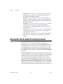
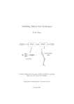
DocumentIt and the Rapid Prototyping Concept
Conventional real-time system development usually takes place in stages
with separate tools for control design, software engineering, data
acquisition, testing, and design documentation. The MATRIXx product
family integrates tools for each stage of system development into a single
environment. This allows a design to move easily from one stage to the
next, making it possible to create a well-documented working prototype
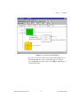
early in the design process. Figure 1-1 shows DocumentIt in the MATRIXx
product line.
Within the MATRIXx design automation product family, a system model
can be built, simulated, analyzed, tested, and debugged using SystemBuild
and Xmath. Real-time code in a high-level language for the model—C or
Ada—using AutoCode and design documentation can be generated
automatically with DocumentIt. The generated application code can be
evaluated on the host with SystemBuild simulation or run on NI real time
hardware. Finally, the generated application code can be cross-compiled
and linked for implementation on an embedded processor. Documentation
can be updated and automatically generated along each step of the process.
DocumentIt User Guide
1-2
ni.com
Chapter 1
Introduction
MATRIXx Product Family
Tools
Xmath
(Analysis/Design)
SystemBuild
(Modeling/Simulation)
AutoCode
(Code Generation)
DocumentIt
(Document Generation)
ASCII Output
Document
Real Time Hardware
Cross-Compilers/
Real-Time
Operating System
FRFrameMaker
MMS Word
InInterleaf
(pSOS or VxWorks)
(Implementation on an
embedded processor)
Figure 1-1. DocumentIt in the MATRIXx Product Line
© National Instruments Corporation
1-3
DocumentIt User Guide
Chapter 1
Introduction
Automatic Document Generation Process
As an integral part of MATRIXx Rapid Prototyping concept, DocumentIt
lets you generate design documentation from a SystemBuild block diagram
model quickly, automatically, and without programming skills.
DocumentIt details the software design in a uniform standardized
documentation format and fully supports the SystemBuild hierarchical
approach to system design.
Because DocumentIt uses templates to format documents and select
specific contents, you can configure DocumentIt to suit your particular
documentation needs. The templates can be readily modified to conform to
any documentation standard. For example, DocumentIt can be used to
generate the following:
•
Detailed description of the design in ASCII format
•
Most industry-standard formats
•
Tables containing SuperBlock and Block inputs and outputs, State
Transition Diagrams, and Global data
•
Documents formatted for FrameMaker (including DOD-STD-2167A)
and Microsoft Word (or any application that reads RTF)
A typical sequence for using DocumentIt is as follows. This sequence
corresponds to the sequence of steps shown in Figure 1-2:
1.
Build and Document the Model.
Develop the continuous-time plant model and corresponding
discrete-time controller SuperBlocks using SystemBuild block
diagrams. The SystemBuild model is built up from a large palette of
blocks which combine to describe the way the model works and how
it should be controlled. DocumentIt automatically extracts information
from the Inputs, Outputs, Document, and Comment fields for
SuperBlocks and primitive blocks.
DocumentIt User Guide
1-4
ni.com
Chapter 1
Introduction
SystemBuild/Xmath
Model Simulation
Step 1
SystemBuild
Model File
Step 2
Interleaf
Markup
Template*
(.rtf)
Step 2
DocumentIt
Design Documentation
Generator
Command
Options
(.dac)
FrameMaker
Markup
Template*
Step 3
Standard
ASCII
Document
Document with
FrameMaker
Markup Cmds.
Standard
Template File
Document with
Interleaf
Markup Cmds.
Document with
Microsoft Word
Commands
Step 4
Step 4
FrameMaker
Interleaf
Step 4
Microsoft
Word
Step 5
*Use markup templates for
general purpose or
DOD-STD-2167A documents
Figure 1-2. DocumentIt Automatic Documentation Generation Process
2.
Customize documentation generation.
Tailor your generated design document using the template
programming language (TPL) provided in DocumentIt. This
programming language lets you implement virtually any template file
© National Instruments Corporation
1-5
DocumentIt User Guide
Chapter 1
Introduction
for a specialized purpose. DocumentIt output in this case is an ASCII
text file, which you can use with almost any text editor. You can edit
the file or print it as a simple unformatted ASCII file.
Typically, the template file contains DocumentIt parameters and
publishing commands such as rich text format (RTF) or FrameMaker
markup language (MML), which DocumentIt writes directly to the
output file.
3.
Generate the design document.
Invoke DocumentIt from inside SystemBuild, from the Xmath
Commands window, or from the operating system prompt. DocumentIt
loads discrete-time and continuous-time SuperBlocks, reading the
associated data to generate the design documentation in accordance
with the template instructions.
4.
Process documents with markup commands.
Import DocumentIt document files with FrameMaker, Interleaf, or
RTF markup commands into FrameMaker, Interleaf, or Microsoft
Word, respectively. These applications automatically recognize the
document formats.
Note RTF can be read by most word processing and desktop publishing programs, but it
is the native format in Word.
5.
Print the formatted document.
Save the model design document in RTF, FrameMaker (MML), or
ASCII format, and send it to a printer in any printer output form such
as PostScript or portable document format (PDF).
Cruise Control Example
This section illustrates the use of DocumentIt. Figure 1-3 shows a modified
version of the cruise control model. This model is found in:
DocumentIt User Guide
(UNIX)
$CASE/DIT/templates/fmaker/general/
Controller_Logic_gen.dat
(Windows)
%CASE%\case\DIT\templates\fmaker\general\
Controller_Logic_gen.dat
1-6
ni.com
Chapter 1
Introduction
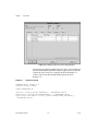
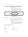
Figure 1-3. Cruise Control SystemBuild Diagram
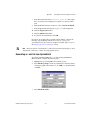
The cruise control model consists of the highest-level SuperBlock, two
embedded SuperBlocks, and associated units. Figure 1-4 shows the
associated SuperBlock Properties dialog. Click Help for information on
each field in the dialog.
© National Instruments Corporation
1-7
DocumentIt User Guide
Chapter 1
Introduction
Figure 1-4. SuperBlock Properties for Cruise Control Diagram
The information from the SuperBlock Properties dialog can be included in
the DocumentIt ASCII output file by using the appropriate keywords in the
template file. The excerpt from a template file shown in Example 1-1
produces entries in the DocumentIt ASCII output file shown in
Example 1-2.
Example 1-1
Template File Excerpt
@SEGMENT MAIN() STRING S1 @
Software Design Document
@SCOPE SUPERBLOCK 0@
Overview : @S1=user_param("OVERVIEW_s", "SUPERBLOCK")@@S1@
Architecture: @user_param("ARCHITECTURE_s", "SUPERBLOCK")@@S1@
System States and Models: @S1=user_param("SYSTEM_STATES_AND_MODES_s",
"SUPERBLOCK")@@S1@
DocumentIt User Guide
1-8
ni.com
Chapter 1
Num Ext. In
Num Ext. Out
Num SuperBlocks
Attribute
Frequency
=
=
=
=
=
Introduction
@num_sb_in_i@
@num_sb_out_i@
@num_blks_in_sb_i@
@sb_attr_s@
@sb_freq_r@
Has Input Data = @sb_has_in_data_b@
@ENDSEGMENT@
Example 1-2
DocumentIt ASCII Output File
==================================
Software Design Document
Overview : This cruise controller regulates vehicle speed around a set
point.
This cruise controller has three external inputs as follows:
the desired "speed" or velocity of the vehicle,
the current "speed,"
the current "acceleration" of the vehicle.
This cruise controller has one external output, which is the throttle
actuator command.
Architecture:
There are three SuperBlocks in this model.
The SuperBlocks are as follows:
the "Differentials" SuperBlock computes the difference between desired and
measured velocity and acceleration, adds computed target acceleration to
measured acceleration, and outputs a servo-limited throttle command based
upon these differences
the "Cruise Control Logic" SuperBlock determines whether or not throttle
position should be altered, based upon the difference between actual and
desired vehicle velocity, and
the "Mux3" SuperBlock determines the target acceleration based upon
inputs from the control logic.
© National Instruments Corporation
1-9
DocumentIt User Guide
Chapter 1
Introduction
System States and Models:
Num Ext. In
Num Ext. Out
Num SuperBlocks
Attribute
Frequency
=
=
=
=
=
This model is enabled and disabled externally.
3
1
3
Discrete
50.0000
Has Input Data = 1
Similarly, information from all SuperBlock/block dialogs and input/output
description dialogs can be included within an ASCII output file by the
appropriate use of the keywords in the template file.
How to Access National Instruments-Supplied Files
At several places in this manual, you are asked to execute, study, or copy
and modify certain files we provide for your use. The paths to the files are
specified by environment variables, which are established by the xmath
startup software for your convenience. For UNIX, the environment
variables are:
Variable
Status (as delivered)
$MTXHOME
Available from operating system or Xmath
Commands window
$SYSBLD
Available from Xmath Commands window and
SystemBuild Load/Save dialog
$XMATH
Available from Xmath Commands window
$CASE
Available from Xmath Commands window
To make $SYSBLD, $XMATH, or $CASE available from the operating
system, in the Xmath Commands window, type:
oscmd ("echo $variable")
where variable is SYSBLD, XMATH, or CASE, as you require. The Xmath
software will display the required path. From the operating system, place
this path in a setenv statement and execute it.
For information on Windows environment variables, refer to the Xmath
User Guide.
DocumentIt User Guide
1-10
ni.com
Chapter 1
Introduction
Related Publications
National Instruments provides a complete library of publications to support
its products. In addition to this guide, publications (from NI and other
sources) that you may find particularly useful when using DocumentIt
include the following:
•
SystemBuild User Guide
•
Xmath User Guide
•
AutoCode User Guide
•
AutoCode Reference
•
Template Programming Language User Guide
•
Military Standard: Defense System Software Development,
DOD-STD-2167A, February 1988
•
MML Reference from Adobe Systems Incorporated
This manual will help you create custom documentation formats using
FrameMaker MML markup language.
For additional documentation, refer to the MATRIXx Help or the NI Web
site at ni.com.
© National Instruments Corporation
1-11
DocumentIt User Guide
Invoking DocumentIt
2
This chapter tells how to generate documents from SystemBuild, Xmath,
and from the operating system prompt.
How to Generate Design Documentation
Using DocumentIt, you can generate design documentation from:
•
SystemBuild—generates a real-time file (.rtf) and then extracts
block and SuperBlock documentation from a model using the Generate
Documentation dialog (the recommended method).
•
Xmath—generates an .rtf file and then extracts block and
SuperBlock documentation from a model using an Xmath command.
Refer to Appendix A, DocumentIt Options, for the Xmath command
options.
•
Operating system prompt—lets you extract block and SuperBlock
documentation from a .rtf file, using the autostar command. Refer
to Appendix A, DocumentIt Options, for the operating system
command options.
Generating Documentation From Within SystemBuild
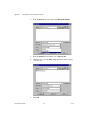
To use DocumentIt while inside SystemBuild, complete the following
steps:
1.
Select a Top-Level SuperBlock. By default, the name of the
SuperBlock you select is used for both the real-time file (RTF) file
and the documentation output file.
2.
Select Tools»DocumentIt from the Catalog Browser (or press
<Ctrl-D>) to open the Generate Documentation dialog. Refer to the
Windows section or the UNIX section for platform-specific
information.
© National Instruments Corporation
2-1
DocumentIt User Guide
Chapter 2
Invoking DocumentIt
3.
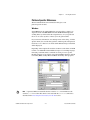
Select your options. The available options include:
Block Parameters
Select the source of the %Var information:
%Vars from Xmath—uses the latest values
of the Xmath variables.
Block Defaults—uses the block’s default
values.
4.
Typecheck
If selected, the Analyzer checks for matching
data types for input and output signals.
AutoCode generates the appropriate data types
in the target language that correspond to the
SystemBuild data types. If not selected, input
and output signals and parameter data are
assumed to be FLOAT. In this case,
DocumentIt only generates the RT_FLOAT
data type for signals and data. Default = 0.
Template File
Specify (or browse for) the DocumentIt
template .tpl or .dac file to be used to
format the documentation. The standard
ASCII template is used by default.
Config File
An options configuration file that lists the
AUTOSTAR settings for both AutoCode and
DocumentIt. The default options file is
autostart.opt. By default, DocumentIt
first looks for a file of that name in the current
working directory; explicitly specified
DocumentIt keywords are evaluated later, and
override any options file settings.
MS Word
Enable special processing for Microsoft Word
RTF file generation. This option is required if
you are using the Microsoft Word template as
described in Appendix E, Generating
Documents Using Microsoft Word.
Click OK and monitor the status of your document generation in the
Xmath Commands window log area.
DocumentIt displays the following message:
Documentation generation complete.
Document generated and saved in file: block_name.doc.
5.
DocumentIt User Guide
Open your generated document in the appropriate editor.
2-2
ni.com
Chapter 2
Invoking DocumentIt
Platform Specific Differences
The DocumentIt Generate Documentation dialog has some
platform-specific features.
Windows
SystemBuild uses the standard Windows selection dialog to display an
output file name in the File name field. The Look in field displays the
working directory which will be the output directory for your generated
file. You can select any drive or directory for the generated file.
If you want more information on standard portions of the dialog, click the
question mark (?) icon on the dialog title bar, and then position the question
mark cursor over a field or icon and click. The Windows help for that field
will be displayed.
Depending on the template file used, the document can be either an ASCII
text file or an ASCII file with embedded word processor markup language
formatting commands. These commands are word processor specific.
Example templates are provided to support FrameMaker, Interleaf, and rich
text format (RTF), used by Microsoft Word and read by other programs.
Note A generated Microsoft Word file has the extension .doc. DocumentIt uses the
extension .rtf for real-time files which can be used with the autostar command as
described in the Generating Documentation from the OS section.
© National Instruments Corporation
2-3
DocumentIt User Guide
Chapter 2
Invoking DocumentIt
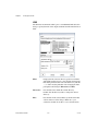
UNIX
The Generate Documentation dialog uses a standard Motif File Selection
dialog to specify the name of the output documentation file in the Selection
field.
DocumentIt User Guide
Filter
Displays the file selection directory path. Uses standard
shell wildcard character(s) to select the files shown in the
Files listing. Default value is the current directory with the
*.cat filter. Pressing <Return> after changing the filter
path updates the listings in Directories and Files.
Directories
Lists the directories within the current directory.
Double-click the directory name to change the current
directory.
Files
Lists the files in the selected directory that meet the filter
criteria. If the rest of the dialog is filled out to your
satisfaction, double-click a file to save to that file name.
2-4
ni.com
Chapter 2
Selection
Invoking DocumentIt
Displays the complete path to the file selected in the Files
listing. Because this name is used for both the RTF file and
the documentation file, any extensions will be stripped
before creating the .rtf and source file names.
Template Information
Appendix B, Generating Documents Using FrameMaker, through
Appendix E, Generating Documents Using Microsoft Word, provide
examples of automatic documentation generation using DocumentIt
templates, as follows:
•
Appendix B, Generating Documents Using FrameMaker, describes
how to generate a general purpose design document using DocumentIt
and FrameMaker templates.
•
Appendix C, Generating 2167A Documents Using FrameMaker,
describes how to generate a sample design document conforming
closely with DOD-STD-2167A using DocumentIt and FrameMaker
templates.
•
Appendix D, Generating 2167A Documents Using Interleaf, describes
how to generate a sample design document conforming closely with
DOD-STD-2167A using DocumentIt and Interleaf templates.
•
Appendix E, Generating Documents Using Microsoft Word, describes
how to generate a sample design document using DocumentIt and
Microsoft Word templates.
•
Appendix F, Generating ASCII Documents, describes how to generate
a sample design document in ASCII text file format using a
DocumentIt template.
Generating Documentation from Xmath
The documentit command lets you process a model to generate design
documentation.
Two syntaxes are supported:
documentit, {model = name1, file = name2,
template=name3}
documentit model, {options}
© National Instruments Corporation
2-5
DocumentIt User Guide
Chapter 2
Invoking DocumentIt
where name1 identifies the model to be processed for documentation
generation. The model can be either:
•
A string in quotes (“”), which must be the name of a SuperBlock that
exists in the current SystemBuild Catalog. This SuperBlock is
analyzed and processed to generate documentation.
•
A variable, not in quotes. Variables should be assigned to a string, the
string must be the name of a SuperBlock in the current catalog. It is
analyzed and processed to generate documentation.
Whenever a file name or other string is included in a command string, it
must be enclosed in quotes, but a variable name must not be in quotes.
name2 is the name for the generated output document file. This value must
be a string or string variable, as well. If the file = name2 option is not
provided, documentation will be generated in the file mode1.doc.
name3 is the name of the template file used to tailor the document. This
value must be a string or string variable. If this option is not provided, the
template _documentit.tpl (in the directory $CASE/DIT/templates/
ascii) is used (%CASE% for Windows).
Refer to Appendix A, DocumentIt Options, for a complete list of
DocumentIt options used in the second command syntax.
Examples:
documentit "topSB"
The system generates a real-time file named topSB.rtf. It loads this file
and processes it to produce the document file. The output file name is
topSB.doc.
documentit "topSB", {template="mytemplate"}
documentit, {model = "topSB", template = "mytemplate"}
Either syntax processes the SuperBlock topSB in the current catalog to
produce documentation, using the template file mytemplate. The output
file name is topSB.doc.
DocumentIt User Guide
2-6
ni.com
Chapter 2
Invoking DocumentIt
Generating Documentation from the OS
If a model file already exists, it is also possible to execute DocumentIt from
the operating system prompt. The input file for processing must be a
real-time file (.rtf). At the operating system prompt, execute the
command:
% autostar {options} model_file.rtf
Many of the options are the same as the fields in the documentation
generation dialog. Refer to Appendix A, DocumentIt Options, for a
complete list of DocumentIt options.
DocumentIt runs, creating a document file. When the operating system
prompt returns, the process is complete.
Examples:
% autostar -h
shows a help display.
% autostar -doc -t FM.tpl SysBld_file.rtf
processes the model file SysBld_file.rtf using a template file named
FM.tpl to produce a document file named SysBld_file.doc. It assumes
the template file FM.tpl exists in your working directory.
Note The DocumentIt real-time file (.rtf) input file is not the same as the rich text
format file (.rtf) word processing output file. Only the file extension is the same.
Generate a Textual Version of a Model
One use of DocumentIt is to generate a textual version of a model. For
example, the TPL sample file (block_info.tpl) shown in Example 2-1
generates output similar to the text shown in Example 2-2, which
documents the Arbitrate Throttle Control SuperBlock from the Supercruise
demo model.
Example 2-1
Sample TPL File for Documenting a Block
@SEGMENT MAIN() INT i, j@@
@LOOPP i eq 0, i lt nsupblks_i, i=i plus 1@@
@SCOPE SUPERBLOCK i@@
superblock name:
@sb_name_s@
superblock inputs:
@num_sb_in_i@
superblock outputs:
@num_sb_out_i@
© National Instruments Corporation
2-7
DocumentIt User Guide
Chapter 2
Invoking DocumentIt
number of blocks:
@num_blks_in_sb_i@
<display other desired superblock attributes here>
block list:
@LOOPP j=0, j lt num_blks_in_sb_i, j=j plus 1@@
@SCOPE BLOCK j@@
block name:
@blk_name_s@
block ID:
@blk_id_i@
block type:
@blk_typ_s@
block inputs:
@num_blk_in_i@
block outputs:
@num_blk_out_i@
<display other desired block attributes here>
@ENDLOOPP@@
--------------------------------------------------@ENDLOOPP@@
@ENDSEGMENT@@
DocumentIt uses the TPL formatting language, such as the
block_info.tpl file shown in Example 2-1, and built-in model
parameters for automatic document generation. This template file
generates default output in Microsoft Word format with the
blockname.doc file name as shown in Example 2-2.
Example 2-2
Sample Output for Arbitrate Throttle Control SuperBlock
superblock name: Arbitrate Throttle Control
superblock inputs:
3
superblock outputs:
1
number of blocks:
3
<display other desired superblock attributes here>
block list:
block name:
throttle switch
block ID:
24
block type:
Data Path Switch
block inputs:
3
block outputs:
1
<display other desired block attributes here>
block name:
Block
block ID:
34
block type:
Relational Operator -- LT-EQ-GT
block inputs:
2
block outputs:
1
<display other desired block attributes here>
DocumentIt User Guide
2-8
ni.com
Chapter 2
Invoking DocumentIt
block name:
Block
block ID:
46
block type:
Logical Operator -- AND-OR-NOT
block inputs:
2
block outputs:
1
<display other desired block attributes here>
Pseudocode for the process of generating text for a SuperBlock is shown in
Example 2-3.
Example 2-3
Pseudocode for Generating a Textual Printout of a Model
<get list of SuperBlock hierarchy>
<loop over all SuperBlocks selected>
<extract, format and print SuperBlock comments, ...>
<get list of all blocks>
<loop over all blocks>
<extract, format and print block comments, ...>
<locate BlockScript blocks, print the code>
<end loop>
<end loop>
© National Instruments Corporation
2-9
DocumentIt User Guide
Customizing the Generated
Documentation
3
You can customize DocumentIt-generated output documentation to suit
your specific needs by using templates. Template files are ASCII files
containing text, interspersed with template command parameters that
specify DocumentIt output.
In addition to template command parameters, template files can also use
publishing software markup commands—for example, Microsoft Word
RTF, Interleaf markup, and FrameMaker MML commands—which
DocumentIt writes directly to the ASCII output file. The markup
commands automatically format the document when it is imported into the
corresponding publishing software.
For details about how to use TPL for DocumentIt output, refer to the
Template Programming Language User Guide.
© National Instruments Corporation
3-1
DocumentIt User Guide
A
DocumentIt Options
This appendix provides additional information about invoking DocumentIt.
Use this appendix together with Chapter 2, Invoking DocumentIt.
Options When Invoking DocumentIt
As described in Chapter 2, Invoking DocumentIt, DocumentIt can be
invoked from the Catalog Browser, the Xmath Commands window, or the
operating system prompt. Table A-1 lists the various DocumentIt options.
From the Catalog Browser, select Tools»DocumentIt.
From the Xmath Commands window, enter the following command. Refer
to the Generating Documentation from Xmath section of Chapter 2,
Invoking DocumentIt.
documentit options
From the operating system prompt, enter the following command. Refer to
the Generating Documentation from the OS section of Chapter 2, Invoking
DocumentIt.
autostar -doc options
Table A-1. Command Options when Invoking DocumentIt
Xmath Option
OS Option
Description
file
-o
A string defining the output file for
generated documentation. If no name is
supplied, the top level SuperBlock name
is used with the .doc extension.
Xmath does not have a help
keyword, but has the
command help autocode
for Netscape help.
-h
Obtains a help display.
© National Instruments Corporation
A-1
DocumentIt User Guide
Appendix A
DocumentIt Options
Table A-1. Command Options when Invoking DocumentIt (Continued)
Xmath Option
OS Option
Description
model
This Xmath option is
used for creating the
.rtf file. When
invoking from the OS,
the .rtf file must
already exist;
therefore, there is no
OS option equivalent.
A text string representing the name of
a SuperBlock in the SystemBuild
Editor—for example, System.
msrtf
-msw1
Provides special parsing for Microsoft
Word documentation generation. Ignores
the \par parameter in the rich text format
(RTF) when you use @@ and merges a
word when it is divided across two lines.
options
-opt
A string specifying the name of the
options file. Options are entered in the file
using the same syntax as if they were
specified in an operating-system call to
AutoCode outside Xmath, except that
options normally passed as strings must
not be quoted. Command options
override all the options in this file, and
the RTF file name cannot be given here.
Single line comments are done by using
// characters. Refer to the Using the
autostar.opt File section for more
information about the options file.
rtf
The name of the .rtf
file must always be
specified when
invoking from the
command prompt.
A string specifying the RTF file name.
You can use the RTF file along with the
standalone AUTOCODE command to
regenerate code. The RTF file is
generated using the CREATERTF
command.
DocumentIt User Guide
A-2
ni.com
Appendix A
DocumentIt Options
Table A-1. Command Options when Invoking DocumentIt (Continued)
Xmath Option
OS Option
tpldac
Description
A string specifying the location of the
template dac file to be used in document
generation. Default file is $XMATH/
-d
../case/DIT/templates/ascii/
documentit.dac (the code template
dac).
tplsrc
A string specifying the location of the
template file to be used in document
generation. The default file is
-t
$XMATH/../case/DIT/templates/
ascii/documentit.tpl (the code
template).
typecheck
Xmath does not have a
help keyword, but has
the command help
autocode for
Netscape help.
Boolean (default=1). When TRUE, this
option enables the checking of variable
types for the SystemBuild analyzer.
Typechecking is on by default.
vars
Xmath does not have a
help keyword, but has
the command help
autocode for
Netscape help.
Boolean (default=1). When TRUE, this
flag forces % variables in the Xmath
workspace to be used. When FALSE,
SystemBuild default block form values
will be used.
Using the autostar.opt File
If you invoke DocumentIt with the same options consistently, you can put
these options into an options file, eliminating error-prone, repetitive typing
each time you invoke DocumentIt. DocumentIt reads the options file at
startup, and performs the options as though you had entered them on the
command line. Although you can use an options file whether you invoke
DocumentIt from the Xmath Commands window or the operating system
prompt, the only options that you can specify in the options file are
operating system command options.
The default options file is autostar.opt. If you have an autostar.opt
file in the current working directory from which you invoke DocumentIt,
the options in that file will be executed when you invoke DocumentIt. If
you specify an option for the command prompt that is also in the options
© National Instruments Corporation
A-3
DocumentIt User Guide
Appendix A
DocumentIt Options
file, the command option overrides the same option in the options file.
Refer to Example A-1 and the following paragraphs.
For different applications, you might need to invoke DocumentIt
differently. For this reason, you can have multiple options files. To invoke
DocumentIt with an options file other than autostar.opt, specify the
name of the options file when you invoke DocumentIt. Refer to
Example A-2 and the following paragraphs.
Options are entered in the options file using the same syntax as if they were
specified in the command syntax. The exception is that map specifications
are not enclosed between quotes. Options can be on one line, separate lines,
or a combination. The RTF file name cannot be specified in the options file.
Single line comments are preceded and followed by // characters.
Example A-1 shows an options file.
Example A-1
Example autostar.opt Options File
// Sample options file //
-t c386_c860_mb2.tpl
-o myoutput
To use this file, invoke DocumentIt as follows:
autostar -doc model.rtf
This invokes DocumentIt with the autostar.opt options file.
Consider the following command:
autostar -doc -o myoutput3 model.rtf
The options file is again used, but the output file option (-o) is specified at
the command prompt, so it overrides the corresponding command in the
options file. The output documentation will be in the myoutput3 file, not
in the myoutput file as specified in the options file.
Example A-2 shows an options file called myopt.opt.
DocumentIt User Guide
A-4
ni.com
Appendix A
Example A-2
DocumentIt Options
Example Options File Called myopt.opt
// Sample options file //
-t c386_c860_mb2.tpl
-o myoutput2
To use this file, invoke DocumentIt as follows:
autostar -doc -opt myopt.opt model.rtf
This invokes DocumentIt with the myopt.opt options file.
If you have both of the above option files in your directory, as shown in
Examples A-1 and A-2, invoking autostar without the -opt option puts the
generated documentation into the myoutput file. The autostar.opt
options file is used. Invoking autostar with the -opt myopt.opt option as
shown in the previous command puts the generated documentation into the
myoutput2 file, as specified in the myopt.opt file.
© National Instruments Corporation
A-5
DocumentIt User Guide
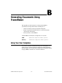
B
Generating Documents Using
FrameMaker
This appendix provides instructions for using the FrameMaker
documentation example. This includes describing how to:
•
Generate documents and encapsulated PostScript files
•
Import encapsulated PostScript files into a generated document
automatically and manually
•
Format table data for FrameMaker
All FrameMaker documentation example files are located in:
(UNIX)
$CASE/DIT/templates/fmaker/general
(Windows)
%CASE%\DIT\templates\fmaker\general
Using Your Own Templates
If you want to generate documentation using your own templates, you
might consider copying the supplied example files and then modifying
them. The purpose of each file is given in Table B-1. FrameMaker markup
language (MML) commands also are listed in Table B-1.
© National Instruments Corporation
B-1
DocumentIt User Guide
Appendix B
Generating Documents Using FrameMaker
Table B-1. FrameMaker Example Files
Filename
Description
fmgp.tpl
This template file determines what information will be
extracted from the model to create an ASCII output file.
Additionally, fmgp.tpl embeds FrameMaker MML
commands, which define how the document will be formatted
when it is imported into FrameMaker. Finally, the template
also embeds an MML command that calls the include file
fmgpinc.mml, which defines what MML commands
FrameMaker should recognize from the FrameMaker
template fmgp.doc.
fmgpinc.mml
This include file specifies what MML commands the
FrameMaker template file fmgp.doc should recognize.
However, the actual format definitions of these commands are
not specified in this include file; rather, the format
specifications for each MML command are incorporated into
fmgp.doc. All MML commands listed in this include file are
given in Table B-2. The table also gives a brief description of
each MML command as it is defined by fmgp.doc.
fmgp.doc
This is a supplied FrameMaker template into which you must
import an ASCII data file generated by DocumentIt using the
DocumentIt template fmgp.tpl.
fmgpTOC.doc
This FrameMaker template receives the table of contents you
generate from fmgp.doc. It is important to consider that
FrameMaker normally generates a TOC file automatically
from a document file, but no format is specified. The purpose
of this file is to provide a suitable format for the TOC, rather
than requiring you to develop one.
Controller_Logic_gen.dat
Controller logic model.
Table B-2. FrameMaker MML Commands
Command
Description
<Author>
Command on the title page; formats the name of the author
providing the document (refer to Figure B-2).
<body1>
Normal text paragraph format.
DocumentIt User Guide
B-2
ni.com
Appendix B
Generating Documents Using FrameMaker
Table B-2. FrameMaker MML Commands (Continued)
Command
Description
<body2>
Indented text paragraph which can be used to align with the
text in a numbered list (first level number).
<body3>
Indented text paragraph which can be used to align with the
text in a numbered list (second level number).
<bull1>
First level bulleted list.
<bull2>
Second level bulleted list.
<chap>
Chapter title.
<CoBody>
Name of the company providing the document given on the
title page. Refer to Figure B-2.
<Date>
Title page entry for the document date. Refer to Figure B-2.
<DocTitle>
Document title. Refer to Figure B-2.
<EXample>
Numbered title of an example (automatic numbering).
<EXinit>
Numbered title of an example (reset count to 1).
<EXtext>
Text format for programming example.
<FIGcap>
Automatically numbered figure caption.
<head1>
First heading level.
<head2>
Second heading level.
<head3>
Third heading level.
<head4>
Fourth heading level.
<head5>
Fifth heading level.
<list1>
Numeric list (automatic numbering).
<list1init>
Numeric list (automatic numbering reset to 1).
<list2>
Alpha list (automatic numbering).
<list2init>
Alpha list (automatic numbering reset to a).
<NOTE>
Note paragraph with the word NOTE included.
© National Instruments Corporation
B-3
DocumentIt User Guide
Appendix B
Generating Documents Using FrameMaker
Table B-2. FrameMaker MML Commands (Continued)
Command
Description
<NOTE+>
Indented paragraph that aligns with the text in the NOTE
paragraph. The word NOTE is not included. This is used when
a note has a second paragraph.
<Rev>
Revision of the document on the title page. Refer to
Figure B-2.
<TBLcap>
Automatically numbered table caption.
Generating a Sample Document
To generate a sample document using DocumentIt and FrameMaker,
complete the following steps:
Note If you want to generate a document from your own model, follow the same steps
given in this example, but use your own model for document generation.
1.
Create a directory in which you want the output document to reside.
2.
Copy all files from:
(UNIX)
$CASE/DIT/templates/fmaker/general
(Windows)
%CASE%\DIT\templates\fmaker\general
to the document directory.
3.
From the Catalog Browser File menu, select Load.
4.
Browse through the document directory and double-click to load the
file Controller_Logic_gen.dat.
5.
In the Catalog pane of the Catalog Browser, select the top-level
SuperBlock—in this case, Controller_Logic.
6.
From the Catalog Browser, select Tools»DocumentIt. The Generate
Documentation dialog appears.
7.
In the File Name field, enter Controller_Logic.mml.
Note An ASCII file with MML markup commands must have a file extension of .mml to
be formatted by FrameMaker.
DocumentIt User Guide
B-4
ni.com
Appendix B
Generating Documents Using FrameMaker
8.
With the Block Parameters combo box, select %Vars from Xmath.
9.
In the Template File field, specify fmgp.tpl as the template file.
10. Select the Typecheck checkbox.
11. To generate the MML document file, click OK.
Changing the Generic Title Page
The MML file that you have generated—in this case,
Controller_Logic.mml—includes a generic title page that appears as
shown in Figure B-1 after it is imported into FrameMaker. If you want to
change the data on the title page, you can accomplish this in one of the three
following ways:
•
Using a text editor, you can edit the fmgp.tpl data. Figure B-2 shows
the data in the fmgp.tpl file that produces the title page shown in
Figure B-1. You should make these changes to fmgp.tpl before you
generate the document from SystemBuild. All subsequent documents
generated by DocumentIt using fmgp.tpl will continue to have your
new title page until you change the contents of fmgp.tpl again.
•
Using a text editor, you can edit the MML output file you have
just generated. Figure B-2 shows the data in the example file
Controller_Logic.mml that produces the title page shown in
Figure B-1. If you regenerate the document, you will have to edit
this file again.
•
If you are familiar with FrameMaker, you can edit the title page after
you import the data into FrameMaker.
If your MML output files contain less than (<) or greater than (>)
characters from your model, you must use your text editor to place a
backslash (\) character in front of these characters. This is required
because these characters will otherwise be interpreted as invalid MML
commands when the *.mml file is imported into FrameMaker.
© National Instruments Corporation
B-5
DocumentIt User Guide
Appendix B
Generating Documents Using FrameMaker
Figure B-1. Generic Title Page
DocumentIt User Guide
B-6
ni.com
Appendix B
Generating Documents Using FrameMaker
<DocTitle>
Software Design Document
<Author>
Author's Name
<Rev>
X.X
<Date>
January 27, 1994
<CoBody>
Company Name
Street Address
City, State ZIP
Figure B-2. Title Page Data in fmgp.tpl and controller_logic_gen.mml
Generating an .eps file from SystemBuild
1.
To place an illustration in your FrameMaker document, you must
insert an anchored frame where you want the figure to appear. Two
anchored frames are inserted into this example so that you can see how
they work. For details on .eps files, refer to the Template
Programming Language User Guide. You can insert an anchored
frame in your document in one of the following ways:
•
Using a text editor, insert @include_img( )@ to automatically
import the illustration when you generate the document.
•
Using a text editor, you can insert the TPL function
@small_frame( )@ (5 in. × 5 in. frame) or
@large_frame( )@ (7 in. × 5 in. frame) in fmgp.tpl where
you want the figure to appear. You should make these changes to
fmgp.tpl before you generate the document from SystemBuild.
After the document is processed and imported into FrameMaker,
a blank frame is placed in your document in the location you
specified. Refer to your FrameMaker documentation to use the
capture feature to capture and import the figure that you want into
the anchored frame.
•
Using a text editor you can insert the MML command <AFrame
<BRect 0 0 h" w">> into the ASCII output file you have just
generated, where the variables h and w are the height and width of
the frame, respectively. After the document is imported into
FrameMaker, a blank frame is placed in your document in the
© National Instruments Corporation
B-7
DocumentIt User Guide
Appendix B
Generating Documents Using FrameMaker
location you specified. Use the FrameMaker capture feature to
capture and import the figure that you want into the anchored
frame.
•
If you are familiar with FrameMaker, you can create an anchored
frame and import the figure you want directly into your
FrameMaker document by completing the following steps.
a.
Highlight the top level SuperBlock (Controller_Logic).
b.
Select File»Page Setup to make any adjustments to the
image before creating the graphics file. In this case, accept the
defaults.
c.
Select File»Print to File.
d.
From the Format pull-down menu, select EncapPostScript.
e.
From the Output pull-down menu, select Separate files.
f.
Click OK.
Note If the .eps illustration is too large for the anchored frame, use the FrameMaker
Graphics Scale option to adjust the size.
2.
From the system prompt in the document directory, start
FrameMaker.
3.
From FrameMaker, open fmgp.doc. You will find a blank file, with
the exception of vertical lines on the left side of the page.
4.
From the pull-down menu, select File»Import.
5.
Select Copy File into Document.
6.
Select Controller_Logic.mml and click OK.
7.
After the import is complete, you will still have a blank page, except
for a single paragraph text symbol at the top of the page somewhat
hidden in the top portion of the vertical lines. Select the paragraph
symbol and delete it.
The title page of the Software Design Document fills the page. Do not
be concerned if the vertical lines display as broken lines; they will be
restored as soon as you page through the document.
Note Do not save this file until you are prompted to do so.
DocumentIt User Guide
B-8
ni.com
Appendix B
Generating Documents Using FrameMaker
Putting Information in Table Format
1.
Page through the document to ensure it meets your needs. If you have
information that you want in table format, complete the following
steps, beginning with step a. If you have no tables, skip to step 2.
a.
Select all the data you want to include in the table, but do not
include the last paragraph symbol in the last row of table data.
Refer to Figure B-3 for an example of exactly what information
you need to select for reformatting.
Table Data
Do not include last
paragraph symbol
of table data
Figure B-3. Marking Data for Table Formatting
b.
From the pull-down menu, select Table»Convert to Table. When
the Convert to Table dialog appears, leave the settings intact and
click OK.
c.
From the pull-down menu, select Table»Resize Columns. When
the Resize Columns dialog appears, click By Scaling to Widths
Totalling. Change the value to 6.25 inches, and click OK. Make
sure that the whole table is selected when you do this. At this point
you can resize individual columns if necessary.
You can also click and drag to highlight one or more table
columns. Click to grab the left column handles, and pull out or
push in to resize the column.
© National Instruments Corporation
B-9
DocumentIt User Guide
Appendix B
Generating Documents Using FrameMaker
d.
Delete any extraneous paragraph symbols that may have appeared
below the table during the conversion process. This is necessary
due to the way FrameMaker converts tables.
e.
Complete steps a through d for each table you have in the
document.
2.
From the pull-down menu, select File»Generate.
3.
Click List Table of Contents, then click Generate.
4.
Leave all the current settings in the Set Up Table of Contents dialog
intact and click OK.
5.
The fmgpTOC.doc file now appears on the screen with a complete list
of sections and subsections. However, since FrameMaker lists all items
in the order in which they appear in a document, some minor
formatting is required for the list of figures and tables. Complete these
tasks as follows:
a.
Page down through the TOC. Using the Cut and Paste features
under the Edit pull-down menu, put all figure references at the end
of the Table of Contents. Do the same thing for all table
references, so they follow the figures.
b.
At the first figure entry, which is now near the end of the Table of
Contents, put the cursor in front of the Figure 1 entry.
c.
Type in Figures and press <Enter>.
d.
Click the word Figures once.
e.
Click the Paragraph Catalog symbol in the upper right corner of
the page to display the Paragraph Catalog. In the catalog, select
the paragraph type TabFigTC.
The heading for the list of figures is now formatted correctly.
f.
DocumentIt User Guide
Repeat this process for the list of tables.
6.
Select the fmgp.doc frame. From the File pull-down menu, select
Save As and assign a new file name to your document file.
7.
(Optional) To print the document, select File»Print.
B-10
ni.com
Appendix B
8.
Generating Documents Using FrameMaker
Select the fmgpTOC.doc frame. From the File pull-down menu, select
Save As. You must specify the identical path and file name as you did
in the previous step for your new document file, only add TOC to the
file name before the extension. Refer to the following example.
Original File Name
New File Name
fmgp.doc
FMsample1.doc
fmgpTOC.doc
FMsample1TOC.doc
This scheme allows you to generate TOCs in the future—when you
modify your document—without having to construct a new TOC
template.
You now have a new document and your original templates have remained
intact.
Note Refer to the Using Your Own Templates section for information about using your
templates instead of the supplied templates.
© National Instruments Corporation
B-11
DocumentIt User Guide
C
Generating 2167A Documents
Using FrameMaker
This appendix describes how to use the FrameMaker 2167A example. This
includes describing how to:
•
Generate documents and encapsulated PostScript files.
•
Import encapsulated PostScript files into a generated document
automatically and manually.
•
Format table data for FrameMaker.
All FrameMaker 2167A example files are located in:
(UNIX)
$CASE/DIT/templates/fmaker/milstd
(Windows)
%CASE%\DIT\templates\fmaker\milstd
Using Your Own Templates
If you want to generate documentation using your own templates, you
might want to consider copying the supplied example files and then
modifying them. The purpose of each file is given in Table C-1.
FrameMaker markup language (MML) commands are listed in Table C-2.
© National Instruments Corporation
C-1
DocumentIt User Guide
Appendix C
Generating 2167A Documents Using FrameMaker
Table C-1. FrameMaker 2167A Example Files
Filename
Description
fmmil.tpl
This template file determines what information will be extracted from the
model to create an ASCII output file. Additionally, fmmil.tpl embeds
FrameMaker MML commands, which define how the document will be
formatted when it is imported into FrameMaker. Finally, the template also
embeds an MML command that calls the include file fmmilinc.mml, which
defines what MML commands FrameMaker should recognize from the
FrameMaker template fmmil.doc.
fmmilinc.mml
This include file specifies what MML commands the FrameMaker template
file fmmil.doc should recognize. However, the actual format definitions of
these commands are not specified in this include file; rather, the format
specifications for each MML command are incorporated into fmmil.doc. All
MML commands listed in this include file are given in the next table. The table
also gives a brief description of each MML command as it is defined by
fmmil.doc.
fmmil.doc
This is a supplied FrameMaker template into which you must import an ASCII
data file generated by DocumentIt using the DocumentIt template
fmmil.tpl.
fmmilTOC.doc
This FrameMaker template receives the table of contents you generate from
fmmil.doc. It is important to consider that FrameMaker normally generates
a TOC file automatically from a document file, but no format is specified. The
purpose of this file is to provide a suitable format for the TOC, rather than
requiring you to develop one.
Table C-2. FrameMaker 2167A MML Commands
Command
Description
<Author>
Last command on the title page; formats the name of the company
providing the document. Refer to Figure C-2.
<body1>
Normal text paragraph format.
<body2>
Indented text paragraph which can be used to align with the text in a
numbered list (first level number).
<body3>
Indented text paragraph which can be used to align with the text in a
numbered list (second level number).
<bull1>
First level bulleted list.
DocumentIt User Guide
C-2
ni.com
Appendix C
Generating 2167A Documents Using FrameMaker
Table C-2. FrameMaker 2167A MML Commands (Continued)
Command
Description
<bull2>
Second level bulleted list.
<CDRL>
Title page CDRL sequence number. Refer to Figure C-2.
<chap>
Chapter heading level.
<Client>
Title page entry for the name of the client for whom the document was
prepared. Refer to Figure C-2.
<contract>
Title page entry for the contract number. Refer to Figure C-2.
<DocTitle>
Document title. Refer to Figure C-2.
<EXample>
Numbered title of an example (automatic numbering).
<EXinit>
Numbered title of an example (reset count to 1).
<EXtext>
Text format for programming example.
<FIGcap>
Automatically numbered figure caption.
<head1>
First heading level (for example, 1.1).
<head2>
Second heading level (for example, 1.1.1).
<head3>
Third heading level (for example, 1.1.1.1).
<head4>
Fourth heading level (for example, 1.1.1.1.1).
<head5>
Fifth heading level (for example., 1.1.1.1.1.1).
<list1>
Numeric list (automatic numbering).
<list1init>
Numeric list (automatic numbering reset to 1).
<list2>
Alpha list (automatic numbering).
<list2init>
Alpha list (automatic numbering reset to a).
<NOTE>
Note paragraph with the word NOTE included.
<NOTE+>
Indented paragraph that aligns with the text in the NOTE paragraph.
The word NOTE is not included. This is used when a note has a second
paragraph.
<PrepBy>
Title page entry. Refer to Figure C-2.
<PrepFor>
Title page entry. Refer to Figure C-2.
<Rev>
Revision and date entry on the title page. Refer to Figure C-2.
© National Instruments Corporation
C-3
DocumentIt User Guide
Appendix C
Generating 2167A Documents Using FrameMaker
Table C-2. FrameMaker 2167A MML Commands (Continued)
Command
Description
<TBLcap>
Table caption.
<TitlePar1>
Title page entries. Refer to Figure C-2.
<TitlePar2>
Title page CSCI name and system name entries. Refer to Figure C-2.
Generating the 2167A Document
To generate the sample 2167A document using DocumentIt and
FrameMaker, complete the following steps:
Note If you want to generate a document from your own model, follow the same steps
given in this example, but use your own model for document generation.
1.
Create a directory in which you want the output document to reside.
2.
Copy all files from:
(UNIX)
$CASE/DIT/templates/fmaker/general
(Windows)
%CASE%\DIT\templates\fmaker\general
to the document directory.
3.
From the Catalog Browser File menu, select Load.
4.
Browse through the document directory and double-click to load the
file Controller_Logic_mil.dat.
5.
In the Catalog pane of the Catalog Browser, select the top-level
SuperBlock—in this case, Controller_Logic.
6.
From the Catalog Browser, select Tools»DocumentIt. The Generate
Documentation dialog appears.
7.
In the File Name field, enter Controller_Logic_mil.mml.
Note An ASCII file with MML markup commands must have a file extension of .mml in
order to be formatted by FrameMaker.
8.
With the Block Parameters combo box, select %Vars from Xmath.
9.
In the Template File field, specify fmgp.tpl as the template file.
10. Click the Typecheck checkbox.
11. To generate the MML document file, click OK.
DocumentIt User Guide
C-4
ni.com
Appendix C
Generating 2167A Documents Using FrameMaker
Changing the Generic Title Page
The MML file that you have generated—in this case,
controller_logic_mil.mml—includes a generic title page that
appears as shown in Figure C-1 after it is imported into FrameMaker. If you
want to change the data on the title page, you can accomplish this in one of
the three following ways:
•
Using a text editor, you can edit the fmmil.tpl data. Figure C-2
shows the data in the fmmil.tpl file that produces the title page
shown in Figure C-1. You should make these changes to fmmil.tpl
before you generate the document from SystemBuild. All subsequent
documents generated by DocumentIt using fmmil.tpl will continue
to have your new title page until you change the contents of
fmmil.tpl again.
•
Using a text editor, you can edit the MML output file you have just
generated. Figure C-2 shows the data in the example file
controller_logic_mil.mml that produces the title page shown in
Figure C-1. If you regenerate the document, you will have to edit this
file again.
•
If you are familiar with FrameMaker, you can edit the title page after
you import the data into FrameMaker.
Note If your output files contain less than (<) or more than (>) characters from your
model, you must use your text editor to place a backslash (\) character in front of these
characters. This is required because these characters will otherwise be interpreted as
invalid MML commands when the *.mml file is imported into FrameMaker.
© National Instruments Corporation
C-5
DocumentIt User Guide
Appendix C
Generating 2167A Documents Using FrameMaker
Revision X.X: June 12, 2000
National Instruments Corp.
Figure C-1. Generic Title Page
DocumentIt User Guide
C-6
ni.com
Appendix C
Generating 2167A Documents Using FrameMaker
<Rev>
Revision X.X: June 12, 2000
<DocTitle>
Software Design Document
<TitlePar1>
For The
<TitlePar2>
CSCI NAME
<TitlePar1>
Of
<TitlePar2>
System Name
<contract>
XXXXXXX
<CDRL>
XXXXXXXXXXX
<PrepFor>
Prepared for:
<Client>
Contracting Agency Name, Department Code
<PrepBy>
Prepared by:
<Author>
Figure C-2. Title Page Data in fmmil.tpl and controller_logic_mil.mm
Generating an .eps file from SystemBuild
To place an illustration in your document, you must insert an anchored
frame where you want the figure to appear. Two anchored frames are
inserted into this example so that you can see how they work. For details on
.eps files, refer to the Template Programming Language User Guide. You
can insert an anchored frame in your document in one of the following
ways:
•
Using a text editor, insert @include_img( )@ to import the
illustration automatically when you generate the document.
You must edit the .eps file generated from SystemBuild in the text
editor and change the first line as follows:
%!PS-ADOBE-1.0
to
%!PS-ADOBE-3.0 EPSF-3.0
© National Instruments Corporation
C-7
DocumentIt User Guide
Appendix C
Generating 2167A Documents Using FrameMaker
•
Using a text editor, you can insert the tpl function
@small_frame( )@ (5 in. × 5 in. frame) or @large_frame( )@
(7 in. × 5 in. frame) in fmgp.tpl where you want the figure to appear.
You should make these changes to fmgp.tpl before you generate the
document from SystemBuild. After the document is processed and
imported into FrameMaker, a blank frame will be placed into your
document in the location you specified. Refer to your FrameMaker
documentation to use the capture feature to capture and import the
figure that you want into the anchored frame.
•
Using a text editor, you can insert the MML command
<AFrame <BRect 0 0 h" w">> into the ASCII output file you have
just generated, where the variables h and w are the height and width of
the frame, respectively. After the document is imported into
FrameMaker, a blank frame will be placed into your document in the
location you specified. Refer to your FrameMaker documentation to
use the capture feature to capture and import the figure that you want
into the anchored frame.
•
If you are familiar with FrameMaker, you can create an anchored
frame and import the figure you want directly into your FrameMaker
document.
a.
Highlight the top level SuperBlock (Controller_Logic).
b.
Select File»Page Setup to make any adjustments to the image
before creating the graphics file. In this case, accept the defaults.
c.
Select File»Print to File.
d.
From the Format pull-down menu, select EncapPostScript.
e.
From the Output pull-down menu, select Separate files.
f.
Click OK.
Note If the .eps illustration is too large for the anchored frame, use the FrameMaker
Graphics Scale option to adjust the size.
The following message appears in the SystemBuild menu bar to confirm
that a hard copy .eps file was generated:
5 SuperBlock(s) hardcopied into file
Controller_Logic.eps
DocumentIt User Guide
1.
From the system prompt in the document directory, invoke
FrameMaker.
2.
From FrameMaker open fmmil.doc. You will find a blank file.
3.
From the pull-down menu, select File»Import.
C-8
ni.com
Appendix C
Generating 2167A Documents Using FrameMaker
4.
Click Copy File into Document.
5.
Select Controller_Logic_mil.mml and click OK.
6.
After the import is complete, you will still have a blank page except for
a single paragraph text symbol at the top of the page. Select the
paragraph symbol and delete it. The Software Design Document title
page will fill the page.
Note Do not save this file until you are prompted to do so.
Putting Information in Table Format
Page through the document to ensure it meets your needs. If you have
information that you want to be in table format, complete the following
steps, beginning with step 1. If you have no tables, skip to step 6.
Select all the data you want to include in the table, but do not include the
last paragraph symbol in the last row of table data. Refer to Figure C-3 for
an example of exactly what information you need to select for reformatting.
Table Data
Do not include last
paragraph symbol
of table data
Figure C-3. Marking Data for Table Formatting
1.
From the pull-down menu, select Table»Convert to Table. When the
Convert to Table dialog appears, leave the settings intact and click OK.
2.
From the pull-down menu, select Table»Resize Columns. When the
Resize Columns dialog appears, click By Scaling to Widths
Totalling. Change the value to 6.25 inches and click OK. Make sure
that the whole table is selected when you do this. At this point, you can
resize individual columns if necessary.
© National Instruments Corporation
C-9
DocumentIt User Guide
Appendix C
Generating 2167A Documents Using FrameMaker
3.
You can also click and drag to highlight one or more table columns.
Click the left mouse to grab the left column handles, and pull out or
push in to resize the column.
4.
Delete any extraneous paragraph symbols that may have appeared
below the table during the conversion process. This is necessary due to
the manner in which FrameMaker converts tables.
5.
Complete the steps 1 through 4 for each table you have in the
document.
6.
From the File pull-down menu, select Generate.
7.
Click List Table of Contents, and then click Generate.
8.
Leave all the current settings in the Set Up Table of Contents dialog
intact and click OK.
9.
The file fmmilTOC.doc now appears on the screen with a complete
list of sections and subsections. However, since FrameMaker lists all
items in the order in which they appear in a document, some minor
formatting is required for the list of figures and tables. Complete the
following steps:
a.
Page down through the TOC. Using the Cut and Paste features
under the Edit pull-down menu, put all figure references at the end
of the Table of Contents. Do the same thing for all table
references, so they follow the figures.
b.
At the first figure entry (now near the end of the Table of
Contents), put the cursor in front of the Figure 1 entry.
c.
Type in Figures and press <Enter>.
d.
Click Figures once.
e.
Click the Paragraph Catalog symbol in the upper right corner of
the page. This will display the Paragraph Catalog. In the catalog,
click the paragraph type TabFigTC. The heading for the list of
figures is now formatted correctly.
f.
Repeat steps a through e for the list of tables.
10. Select the fmmil.doc frame. From the File pull-down menu, select
Save As and assign a new file name to your document file. If you wish,
you can print the file at this time.
DocumentIt User Guide
C-10
ni.com
Appendix C
Generating 2167A Documents Using FrameMaker
11. Select the fmmilTOC.doc frame. From the File pull-down menu,
select Save As. Now, you must specify the identical path and file name
as you did in the previous step for your new document file, only add
TOC to the file name before the extension. Refer to the following
example.
Original File Name
New File Name
fmmil.doc
FMsample1.doc
fmmilTOC.doc
FMsample1TOC.doc
This scheme allows you to generate TOCs in the future—when you
modify your document—without having to construct a new TOC
template.
You now have a new document and your original templates have remained
intact. You can now close your files.
Note Refer to the Using Your Own Templates section for information about using your
templates instead of the supplied templates.
© National Instruments Corporation
C-11
DocumentIt User Guide
D
Generating 2167A Documents
Using Interleaf
Here are instructions for using the Interleaf 2167A example. This tutorial
tells how to:
•
Generate documents and encapsulated PostScript files.
•
Import epsf files into a generated document automatically and
manually.
•
Format table data for Interleaf.
All Interleaf 2167A example files are located in:
(UNIX)
$CASE/DIT/templates/ileaf/milstd
(Windows)
%CASE%\DIT\templates\ileaf\milstd
Using Your Own Templates
If you want to generate documentation using your own templates, you
might want to consider copying the supplied example files and then
modifying them. The purpose of each file is listed in Table D-1, and
Interleaf markup commands are listed in Table D-2.
© National Instruments Corporation
D-1
DocumentIt User Guide
Appendix D
Generating 2167A Documents Using Interleaf
Table D-1. Interleaf 2167A Example Files
Filename
Description
ilmil.tpl
This template file determines what information will be extracted
from the model to create an ASCII output file. Additionally,
ilmil.tpl embeds Interleaf markup commands, which define
how the document will be formatted when it is opened under
Interleaf. Finally, the template also embeds a markup command that
calls the include file ilmilinc, which defines how the document
will be formatted by Interleaf.
ilmilinc
This include file specifies the markup commands that Interleaf will
use to format the ASCII output file generated by DocumentIt. All
markup commands listed in this include file are listed in Figure D-2.
The table also gives a brief description of each command as it is
defined by ilmilinc.
Controller_Logic_mil
.dat
Controller logic model.
Table D-2. Interleaf Markup Commands
Command
Description
<“Author”>
Command on the title page that formats the name of the company
providing the document. Refer to Figure D-2.
<“body1”>
Normal text paragraph format.
<“body2”>
Indented text paragraph which can be used to align with the text in
a numbered list (first level number).
<“body3”>
Indented text paragraph which can be used to align with the text in
a numbered list (second level number).
<“CDRL”>
Title page CDRL sequence number. Refer to Figure D-2.
<“chap”>
Chapter heading level.
<“Client”>
Title page entry for the name of the client for who the document was
prepared. Refer to Figure D-2.
<“contract”>
Title page entry for the contract number. Refer to Figure D-2.
<“DocTitle”>
Document title. Refer to Figure D-2.
DocumentIt User Guide
D-2
ni.com
Appendix D
Generating 2167A Documents Using Interleaf
Table D-2. Interleaf Markup Commands (Continued)
Command
Description
<“dummy”>
First paragraph on the title page. This is an empty place holder
required to provide the correct spacing from the top of the page.
<“FIGcap”>
Automatically numbered figure caption.
<“head1”>
First heading level (for example, 1.1).
<“head2”>
Second heading level (for example, 1.1.1).
<“head3”>
Third heading level (for example, 1.1.1.1).
<“head4”>
Fourth heading level (for example, 1.1.1.1.1).
<“head5”>
Fifth heading level (for example, 1.1.1.1.1.1).
<“list1”>
Upper case Alpha list (automatic numbering).
<“list2”>
Numeric list (automatic numbering).
<“list3”>
Lowercase alpha list (automatic numbering).
<“NOTE”>
Note paragraph with the word NOTE included.
<“NOTE+”>
Indented paragraph that aligns with the text in the NOTE paragraph.
The word NOTE is not included. This is used when a note has a
second paragraph.
<“PrepBy”>
Title page entry. Refer to Figure D-2.
<“PrepFor”>
Title page entry. Refer to Figure D-2.
<“Rev”>
Revision and date entry on the title page. Refer to Figure D-2.
<“row”>
Table row.
<“TBLcap”>
Table caption.
<“TBLhead”>
Column headings in a table.
<“TitlePar1”>
Title page entries. Refer to Figure D-2.
<“TitlePar2”>
Title page CSCI name and system name entries. Refer to
Figure D-2.
© National Instruments Corporation
D-3
DocumentIt User Guide
Appendix D
Generating 2167A Documents Using Interleaf
Generating the 2167A Document
To generate the sample 2167A document using DocumentIt and Interleaf,
complete the following steps:
Note If you want to generate a document from your own model, follow the same steps
given in this example, but use your own model for document generation.
1.
2.
From your system prompt, go to your Interleaf desktop directory
(do not invoke Interleaf) using the change directory command.
Copy all files from:
(UNIX)
$CASE/DIT/templates/fmaker/general
(Windows)
%CASE%\DIT\templates\fmaker\general
to the document directory.
3.
From the Catalog Browser File menu, select Load.
4.
Browse through the document directory and double-click to load the
file Controller_Logic_mil.dat.
5.
In the Catalog pane of the Catalog Browser, select the top-level
SuperBlock (in this case, Controller_Logic).
6.
From the Catalog Browser, select Tools»DocumentIt. The Generate
Documentation dialog will appear.
7.
In the File Name field, enter Controller_Logic_mil.asc.
8.
With the Block Parameters combo box, select %Vars from Xmath.
9.
In the Template File field, specify ilmil.tpl as the template file.
10. Click the Typecheck checkbox.
11. To generate the ASCII document file, click OK.
Changing the Generic Title Page
1.
The ASCII file that you have generated—in this case,
controller_logic_mil.asc—includes a generic title page that
appears as shown in Figure D-1 after it is opened from Interleaf. If you
want to change the data on the title page, you can accomplish this in
one of the three following ways:
•
DocumentIt User Guide
Using a text editor you can edit the ilmil.tpl data. refer to
Figure D-2 shows the data in the ilmil.tpl file that produces
the title page shown in Figure D-1. You should make these
changes to ilmil.tpl before you generate the document from
SystemBuild. All subsequent documents generated by
D-4
ni.com
Appendix D
Generating 2167A Documents Using Interleaf
DocumentIt using ilmil.tpl will continue to have your new
title page until you change the contents of ilmil.tpl again.
•
Using a text editor you can edit the ASCII output file you have just
generated. Figure D-2 shows the data in the example file
controller_logic_mil.asc that produces the title page
shown in Figure D-1. If you regenerate the document, you will
have to edit this file again.
•
If you are familiar with Interleaf, you can edit the title page after
you have opened the file from Interleaf.
2.
From the system prompt, invoke Interleaf.
3.
From Interleaf open Controller_Logic_mil.asc.
4.
After the file is opened, you will see that it is completely formatted.
5.
If the new document meets your specifications, you can save and
print it.
Note Refer to the Using Your Own Templates section for information about using your
templates instead of the supplied templates.
You can use the DocumentIt template ilmil.tpl and its associated
include file ilmilinc in precisely the same manner for your own models
to generate a document using Interleaf.
To generate documentation using your own templates, copy the supplied
example files and modify them. The purpose of each file is given in
Table D-1.
© National Instruments Corporation
D-5
DocumentIt User Guide
Appendix D
Generating 2167A Documents Using Interleaf
Revision X.X: November 26, 1999
National Instruments Corp.
Figure D-1. Generic Title Page
DocumentIt User Guide
D-6
ni.com
Appendix D
Generating 2167A Documents Using Interleaf
<“Rev”>
Revision X.X: November 26, 1999
<“DocTitle”>
Software Design Document
<“TitlePar1”>
For The
<“TitlePar2”>
CSCI NAME
<“TitlePar1”>
Of
<“TitlePar2”>
System Name
<“contract”>
XXXXX.XX
<“CDRL”>
XXXXXX.nnn
<“PrepFor”>
Prepared for:
<“Client”>
Contracting Agency Name, Department Code
<“PrepBy”>
Prepared by:
<“Author”>
National Instruments Corporation
Figure D-2. Title Page Data in ilmil.tpl and controller_logic_mil.doc
© National Instruments Corporation
D-7
DocumentIt User Guide
Appendix D
Generating 2167A Documents Using Interleaf
Adding a Plot or SystemBuild Diagram to an Interleaf Document
1.
To place a plot or SystemBuild diagram in your Interleaf document,
complete the following steps:
a.
Use the hardcopy command to create a PostScript file of each
plot or SystemBuild diagram you want to include.
b.
Convert each PostScript file to an Interleaf image file. The
following diagram illustrates the conversion process (using
psfilt) for each PostScript file.
file.ps
psfilt
file.ps1.img
Run each PostScript file through the Interleaf psfilt filter by
selecting Custom»Misc»psfilt.
Note If the psfilt filter is not set up, refer to your Interleaf manual for instructions.
2.
Use the include_img segment to add the image to your generated
document. Refer to Chapter 3 of the Template Programming
Language User Guide for information about include_imG. Complete
the following steps:
a.
At the bottom of the $ISIHOME/platform/case/DIT/
templates/ileaf/milstd/ilmil.tpl template file is a
SEGMENT include_img line. Example D-1 shows a portion of
this SEGMENT section. Details of the frame itself are omitted.
Include this SEGMENT section in your own TPL file.
Example D-1
Example of include_img in TPL File
@SEGMENT include_img()@
<Frame,
Name =
Placement =
Horizontal Alignment =
Width =
Width =
Height =
Height =
DocumentIt User Guide
"floating",
Following Anchor,
Center,
6.50 Inches,
Page Without Margins,
9 Inches,
Page Without Margins,
D-8
ni.com
Appendix D
Page # =
Diagram =
Generating 2167A Documents Using Interleaf
Autonum,
V11,
(g9,1,0,
(i18,1,0,,0,0,8.5333325,0,0,10.9999992,0,0,2559,3299,1,0,7,0,0,8.5333325,10
.999
9992,673657859,1,2559,0,0,3299,0,0,2559,3299,0,0,0,0,0,2559,3299,1,255,
@sb_mangled_name_s.ps1.img,2,639,0,0,824,0,0,2559,3299,0,0,0,0,0,486,674,1,
1,3157(X0,3157,FBC8FCFCFCFCFCFCFCFCFCFCFCFCFCFCFCFCFCFCFCFCFCFCFCFCFCFCFCFC
FCFCFCFC
.
.
.
(rest
of
frame)
FC91F9C706070EC7010AFCA1E50114FCA1EB0128FCA1F029FC9AC9E12D71FC9AC9DE5D79FC1
CAC1C896DFE4FF))
(E16,0,0,,5,1,1,0.0533333,1,15,0,0,1,0,0,0,1,5,127,7,0,0,7,0,1,1,0.0666667,
0.06
66667,6,6,0,0.0666667,6))>
@ENDSEGMENT@
b.
Scope on a SuperBlock. The @include_img @ statement in the
SEGMENT section includes the currently scoped SuperBlock image
file in your generated document.
If necessary, you can customize the image in the include_img
segment. Refer to Example D-1. Consult your Interleaf manual.
You should be familiar with Interleaf markup language.
c.
© National Instruments Corporation
To incorporate a plot, make a copy of the include_img segment,
shown in Example D-1, and replace @[email protected],
highlighted in Example D-1, with the name of your plot image
file.
D-9
DocumentIt User Guide
E
Generating Documents Using
Microsoft Word
This appendix describes how to use the Microsoft Word documentation
example. This includes describing how to:
•
Generate documents and encapsulated PostScript files.
•
Import Enhanced Metafile (.emf) files into a generated document
automatically and manually.
•
Format table data for Microsoft Word.
All Microsoft Word documentation example files for Windows platforms,
including a sample file that demonstrates these tasks, are located in the
%CASE%\DIT\templates\msword\general\mswgp.wrd file.
Using Your Own Templates
To customize your generated document, make a copy of this file in your
local directory and make appropriate changes. You must regenerate your
document every time you make changes to mswgp.tpl and mswgp.wrd.
If you want to generate documentation using your own templates, consider
copying the supplied example files and then modifying them. The purpose
of each file is listed in Table E-1.
Note Your templates must be in rich text format (RTF), with TPL commands included. Do
not make a template in Microsoft Word *.doc format.
The mswgp.tpl and mswgp.wrd files are in the %CASE%\DIT\
templates\msword\general directory. The
Controller_Logic_gen.dat file is in the %CASE%\DIT\templates\
ascii directory.
© National Instruments Corporation
E-1
DocumentIt User Guide
Appendix E
Generating Documents Using Microsoft Word
Table E-1. Microsoft Word Documentation Example Files
Files in %CASE%\DIT\templates\msword\general:
mswgp.tpl
The template file you must specify when using DocumentIt to
generate an ASCII output file for use with the Word general
purpose documentation. It determines what information is
extracted from the model to create an ASCII output file.
mswgp.wrd
This is a template file included in the mswgp.tpl file. This file
specifies RTF commands, which are recognized by Word. It
contains the template TPL command to search the model for
SuperBlocks and Blocks, and has RTF commands embedded
with template TPL commands to generate the output document.
You can load this file into Word to change the template program
or font settings for the title/section names. The changes appear
when you regenerate the document. Load this document into
Word, to see what the generated document will look like.
Files in %CASE%\DIT\templates\ascii:
Controller_Logic_gen.dat
Controller logic model.
Generating a Sample Document
To generate a sample document using DocumentIt and Microsoft Word,
complete the following steps:
Note If you want to generate a document from your own model, follow the same steps
given in this example, but use your model for document generation.
1.
Create a directory where you want the output document to reside.
2.
Copy all files from %CASE%\DIT\templates\msword\general to
the document directory.
3.
From the Catalog Browser, select File»Load.
4.
Browse through the document directory and double-click to load the
Controller_Logic_gen.dat file.
DocumentIt User Guide
5.
In the Catalog pane of the Catalog Browser, select the top-level
SuperBlock (in this case, Controller_Logic).
6.
From the Catalog Browser, select Tools»DocumentIt. The Generate
Documentation dialog appears.
E-2
ni.com
Appendix E
Generating Documents Using Microsoft Word
7.
In the File Name field, enter Controller_Logic.doc. This output
file is created in your working directory unless you specify another
path.
8.
With the Block Parameters combo box, select %Vars from Xmath.
9.
In the Template File field, specify msgwp.tpl as the template file.
10. Click the Typecheck checkbox.
11. Click the MS Word checkbox.
12. To generate the document file, click OK.
If you have any graphics files to include in the document, complete the
following steps, beginning with the Generating an .emf file from
SystemBuild section. If you have no graphics to include, skip to step 1 of
the Changing the Generic Title Page section.
Note After you generate a document file, you may need to make format changes to select
desired fonts or font sizes, or make other typographic choices.
Generating an .emf file from SystemBuild
To generate an Enhanced Metafile (.emf file) from SystemBuild for
Microsoft Word, complete the following steps:
1.
Highlight the top level SuperBlock (Controller_Logic).
2.
Select File»Page Setup to make any adjustments to the image before
creating the graphics file. In this case, click OK to accept the defaults
or Cancel.
3.
Select File»Print to File.
© National Instruments Corporation
E-3
DocumentIt User Guide
Appendix E
Generating Documents Using Microsoft Word
4.
From the Format pull-down menu, select Enhanced Metafile.
5.
From the Output pull-down menu, select Separate files.
6.
(Optional) You can use the Files of type pull-down menu to display
.emf files only.
7.
DocumentIt User Guide
Click OK.
E-4
ni.com
Appendix E
8.
Generating Documents Using Microsoft Word
By default DocumentIt automatically includes all the SuperBlock
diagrams in the generated document. This is done by inserting
template function @include_img@ under every SuperBlock scope
where the image is to be included. The template mswgp.tpl is written
to handle only importing .emf files into the Word document. The
generated document has links to the .emf files in your local directory.
Whenever you update the graphics file, it will be automatically
reflected in your generated document.
@include_img@ is a template TPL segment defined in mswgp.tpl. This
segment contains the RTF commands to include a graphics file named
@[email protected]. The @sb_mangled_name_s@ token is
filled in with the appropriate SuperBlock when you scope to a particular
SuperBlock. For details on .emf files and scoping SuperBlocks, refer to the
Template Programming Language User Guide.
A typical example to include SuperBlock 1 graphics into your document
would look like this:
@SCOPE SUPERBLOCK 1@
@include_img( )@
Changing the Generic Title Page
1.
© National Instruments Corporation
The document file that you have generated—in this case,
Controller_Logic.doc—includes a generic title page that appears
after it is imported into Microsoft Word, as shown in Figure E-1. If you
want to change the data on the title page or change the template TPL
commands, you can accomplish this in one of the three following
ways. Refer to the Using Your Own Templates section:
•
If you are familiar with Microsoft Word, load the mswgp.wrd file.
Word interprets the RTF in this file and displays the template
program commands along with chapter titles, section headings.
You can edit the title page in the first page and save the document
after you open the document in Word. All subsequent documents
generated by DocumentIt using mswgp.wrd continue to have your
new title page until you change mswgp.wrd again.
•
Using a text editor, you can edit the mswgp.wrd file. If you are
familiar with RTF format, you can search for title generation and
modify it there. You should make these changes to mswgp.wrd
before you generate the document from SystemBuild. All
subsequent documents generated by DocumentIt using
mswgp.wrd continue to have your new title page until you change
mswgp.wrd again.
E-5
DocumentIt User Guide
Appendix E
Generating Documents Using Microsoft Word
•
Using a text editor, you can edit the output document you have just
generated. If you are familiar with RTF format, you can search for
title generation and modify it there. If you regenerate the
document, you have to edit this file again.
2.
Generate a new DocumentIt output file.
3.
Start Microsoft Word.
4.
From the File pull-down menu, select Open.
5.
In the Open dialog, select Controller_Logic.doc and click OK. You
can verify your changes in the new output file.
Figure E-1. Generic Title Page
If you have graphics files you want to include in the document, refer to the
Importing Graphics section. If you have tabular information, refer to the
Creating Tables section.
DocumentIt User Guide
E-6
ni.com
Appendix E
Generating Documents Using Microsoft Word
Importing Graphics
1.
To place an illustration in your document manually, you must insert an
anchored frame in the page where you want the figure to appear. You
can insert an anchored frame in your document by selecting the Insert
pull-down menu. A blank frame will be placed into your document in
the location you specified.
2.
Now you can select Picture under the Insert pull-down menu. There,
you can select the graphics file you want to import. Click Link to File
in the dialog, to create a link to your graphics file. Refer to your
Microsoft Word documentation for more information about using the
Insert utility to insert and import pictures.
Creating Tables
You can use DocumentIt to format tabular data to open as formatted tables
when opened in Microsoft Word. These tables display as standard
Microsoft Word tables. To see an example, generate the example document,
and then examine the mswgp.wrd template file using Microsoft Word. For
information on how to create tables, see the procedure in the next section.
Converting Tabular Data to Tables
To set up tabular data so the DocumentIt template converts them to
Microsoft Word tables, the input data must have Tab characters (>)
separating columns and end-of-paragraph characters (¶) separating rows.
Complete the following steps to create a table.
Select all the data you want to include in the table, but do not include the
last paragraph symbol in the last row of table data. Refer to Figure E-2 for
an example of exactly what information you need to select for reformatting.
© National Instruments Corporation
E-7
DocumentIt User Guide
Appendix E
Generating Documents Using Microsoft Word
Table Data
Do not include last
paragraph symbol
of table data
Figure E-2. Marking Data for Table Formatting
1.
From the pull-down menu, select Table»Convert Text to Table.
When the Convert Text to Table dialog appears, select AutoFormat
and select Grid 5 under that. Then leave the settings intact and click
OK for the AutoFormat, and click OK for the Text to Table dialog.
You can choose any design under the AutoFormat.
2.
Delete any extraneous paragraph symbols that may have appeared
below the table during the conversion process. This is necessary due to
the way Microsoft Word converts tables.
3.
Complete steps 1 and 2 for each table you have in the document. If you
are going to choose the same format for all the tables, then follow step
a, and select Repeat Text to Table under the Edit pull-down menu.
This will repeat the macro for the table conversion.
4.
Save your document.
Creating a Table of Contents
The DocumentIt template is unable to generate a table of contents (TOC);
however, the template does create sections within the document so that it is
easy to have Microsoft Word generate the TOC.
DocumentIt User Guide
1.
Go to the Table of Contents page in the document and place the cursor
on that page.
2.
From the pull-down menu, select Insert»Index and Tables. When the
dialog appears, click List Table of Contents.
E-8
ni.com
Appendix E
3.
Generating Documents Using Microsoft Word
Leave all the current settings in the Set Up Table of Contents dialog
intact and click OK.
Microsoft Word fills up the page with the Table of Contents. As Word
lists all items in the order in which they appear in a document, some
minor formatting is required for the list of figures. Repeat this process
for the list of tables.
4.
© National Instruments Corporation
From the pull-down menu, select File»Save to save the document.
E-9
DocumentIt User Guide
F
Generating ASCII Documents
This appendix describes how to use the ASCII document example. All
ASCII document example files are located in:
(UNIX)
$CASE/DIT/templates/ascii/general
(Windows)
%CASE%\DIT\templates\ascii\general
The files in this directory are:
This is the supplied default template file
that is used by DocumentIt to generate an
ASCII output file when no other template
file is specified.
documentit.tpl
Controller_Logic_gen.dat Controller logic model
Note If you want to generate a document from your own model, complete the following
steps given in the example that follows, but use your model for document generation.
To generate the sample ASCII document using DocumentIt, complete the
following steps:
1.
2.
Create a directory for the output document (for example, docout).
Copy the template files from:
(UNIX)
$CASE/DIT/templates/ascii/general
(Windows)
%CASE%\DIT\templates\ascii\general
to the document directory.
3.
From the Catalog Browser File menu, select Load.
4.
Browse through the document directory and double-click to load the
file Controller_Logic_gen.dat.
5.
In the Catalog pane of the Catalog Browser, select the top-level
SuperBlock—in this case, Controller_Logic.
© National Instruments Corporation
F-1
DocumentIt User Guide
Appendix F
Generating ASCII Documents
6.
From the Catalog Browser, select Tools»DocumentIt. The Generate
Documentation dialog appears.
7.
In the File name field, enter a name for your document—for example,
Controller_Logic_gen.txt.
8.
With the Block Parameters combo box, select %Vars from Xmath.
9.
In the Template File field, specify documentit.tpl as the template
file.
10. Select the Typecheck checkbox.
11. To generate the ASCII document file, click OK.
You can use the default template documentit.tpl to generate an ASCII
document for any valid model.
To generate documentation using your own templates:
DocumentIt User Guide
•
Copy documentit.tpl file.
•
Modify it to your specifications using the TPL programming
information described in the Template Programming Language User
Guide. You can also embed markup language commands to import the
ASCII files into your software publishing application, or print the
document.
F-2
ni.com
Technical Support and
Professional Services
G
Visit the following sections of the National Instruments Web site at
ni.com for technical support and professional services:
•
Support—Online technical support resources at ni.com/support
include the following:
–
Self-Help Resources—For answers and solutions, visit the
award-winning National Instruments Web site for software drivers
and updates, a searchable KnowledgeBase, product manuals,
step-by-step troubleshooting wizards, thousands of example
programs, tutorials, application notes, instrument drivers, and
so on.
–
Free Technical Support—All registered users receive free Basic
Service, which includes access to hundreds of Application
Engineers worldwide in the NI Discussion Forums at
ni.com/forums. National Instruments Application Engineers
make sure every question receives an answer.
For information about other technical support options in your
area, visit ni.com/services or contact your local office at
ni.com/contact.
•
Training and Certification—Visit ni.com/training for
self-paced training, eLearning virtual classrooms, interactive CDs,
and Certification program information. You also can register for
instructor-led, hands-on courses at locations around the world.
•
System Integration—If you have time constraints, limited in-house
technical resources, or other project challenges, National Instruments
Alliance Partner members can help. To learn more, call your local
NI office or visit ni.com/alliance.
If you searched ni.com and could not find the answers you need, contact
your local office or NI corporate headquarters. Phone numbers for our
worldwide offices are listed at the front of this manual. You also can visit
the Worldwide Offices section of ni.com/niglobal to access the branch
office Web sites, which provide up-to-date contact information, support
phone numbers, email addresses, and current events.
© National Instruments Corporation
G-1
DocumentIt User Guide
Index
Symbols
example ASCII output file, 1-9
example template file, 1-8
file location, F-1
FrameMaker mml commands, B-2
from OS, 2-7
from SystemBuild, 2-1, 2-5
from Xmath, 2-5
generating ASCII documents, F-1
generating the design document, 1-6
how to, 2-1
printing the formatted document, 1-6
processing markup commands, 1-6
sequence, 1-4
SystemBuild dialog, 2-1
title page, B-7, D-7
using publishing software, 1-6
documentation
conventions used in the manual, iv
NI resources, G-1
documenting a block, 2-7
DocumentIt
See also documentit command
customizing, 3-1
example of usage, 1-6
SystemBuild diagram, 1-9
template file, 1-8
invoking, 1-6
from SystemBuild, 2-1
from Xmath, 2-1
using autostar command, 2-7
options, A-1, A-3
using (sequence), 1-4
documentit command
options
string, 2-5
variable, 2-5
.dac file, 2-2
.emf file, E-1, E-3
.rtf file, 2-1
.tpl file, 2-2
@sb_mangled_name_s@ token, E-5
A
As, A-1
ASCII
document example, F-1
documentit, tpl function, F-1
autostar command, options, 2-1, 2-7, A-1
autostar.opt, A-3
C
code
generated application, 1-2
real-time, 1-2
Config File, 2-2
conventions used in the manual, iv
Ctrl-D, 2-1
D
design
automation, 1-2
generating documents, 1-6
diagnostic tools (NI resources), G-1
dialog, Generate Documentation for
SuperBlock, B-4, C-4
document
generation, 1-4, 1-5
customizing, 1-5, 3-1
example, 1-6
© National Instruments Corporation
I-1
DocumentIt User Guide
Index
DOD-STD-2167A, 1-11
drivers (NI resources), G-1
fmgpTOC.doc, B-10, B-11
fmmil.doc, C-8, C-10
fmmilTOC.doc, C-10, C-11
general purpose document
example files, B-1
mml commands, B-2
E
encapsulated PostScript, D-1
Enhanced Metafile, E-3
eps file
generating
FrameMaker, B-7, C-7
Interleaf, D-8
Microsoft Word, E-3, E-7
epsf, D-1
examples
ASCII document, F-1
autostar command, 2-7
documentit command, 2-6
FrameMaker 2167A document, C-1
FrameMaker 2167A document
generation, C-4
FrameMaker documents
general purpose, B-5
procedure, B-4, C-4
Interleaf document, D-1
Microsoft Word document, E-1
RTF document, E-1
examples (NI resources), G-1
G
Generate Documentation for SuperBlock
dialog, B-4, C-4
generated application code, 1-2
generating a textual version of a model, 2-7
generation code, options, A-1
graphical user interface, 2-1
H
help, technical support, G-1
HyperBuild, options
error checking, 2-2
Generate KR compatible declarations, 2-2
Typecheck, 2-2
I
illustrations in documents
FrameMaker, B-7, C-7, D-8
fmgp.doc, B-8
Interleaf, plot or SystemBuild
diagram, D-8
Microsoft Word, E-7
importing graphics, E-7
instrument drivers (NI resources), G-1
Interleaf
example document, D-1
example files, description, D-2
general purpose document example
files, D-1
markup commands, D-2
F
File, A-3
FrameMaker
example
2167A document, C-1
2167A document generation, C-4
2167A mml commands, C-2
file containing < or >, B-5
procedure, B-4, C-4
example files
description, B-2, C-2
fmgp.doc, B-8, B-10
DocumentIt User Guide
I-2
ni.com
Index
K
R
KnowledgeBase, G-1
rapid prototyping, 1-2
DocumentIt, 1-4
real-time code, 1-2
real-time file, 2-1, 2-7
related publications, 1-11
RTF
example document, E-1
M
manual organization, 1-1
markup commands, Interleaf, D-2
MATRIXx, 1-2, 1-4, 1-11
block diagram, 1-3
DocumentIt, 1-3
document generation process
diagram, 1-5
Microsoft Word, see Word.
mml commands, B-2, C-2
2167A example, C-2
general purpose example, B-2
mml file extension, C-4
model
building, 1-4
documenting, 1-4
S
software (NI resources), G-1
support, technical, G-1
T
tables in documents, FrameMaker, B-9, C-9
technical support, G-1
templates, 1-4
examples, 1-4
keywords, 1-10
use of, 3-1
use with publishing software, 3-1
user-written, B-1, C-1, D-1, E-1, F-2
training and certification (NI resources), G-1
troubleshooting (NI resources), G-1
N
National Instruments support and
services, G-1
O
U
operating system prompt, 2-7
options, 2-7
output document, F-1
using templates. See templates.
P
programming examples (NI resources), G-1
prompt
operating system, 2-7
© National Instruments Corporation
I-3
DocumentIt User Guide
Index
W
Web resources, G-1
Word
add SystemBuild .emf file, E-3
add SystemBuild .eps file, E-3
Controller_Logic_gen.dat, E-2
document example files, E-1
example files
Controller_Logic_gen.dat, E-2
mswgp.tpl, E-2
mswgp.wrd, E-2
generate a sample document, E-2
generate Table of Contents, E-8
import graphics, E-7
DocumentIt User Guide
I-4
ni.com