1
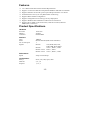
NPort Express Hardware Installation Guide for DE-211 Sixth Edition, May 2006 Moxa Technologies Co., Ltd. Tel: +886-2-8919-1230 Fax: +886-2-8919-1231 www.moxa.com [email protected] (Worldwide) [email protected] (The Americas) 1 NPort Express Hardware Installation Guide for DE-211 The software described in this manual is furnished under a license agreement and may be used only in accordance with the terms of that agreement. Copyright Notice Copyright © 2006 Moxa Technologies Co., Ltd. All rights reserved. Reproduction without permission is prohibited. Trademarks MOXA is a registered trademark of The Moxa Group. All other trademarks or registered marks in this manual belong to their respective manufacturers. Disclaimer Information in this document is subject to change without notice and does not represent a commitment on the part of Moxa. Moxa provides this document “as is,” without warranty of any kind, either expressed or implied, including, but not limited to, the particular purpose. Moxa reserves the right to make improvements and/or changes to this manual or the product(s) and/or program(s) described herein at any time. Information provided in this manual is intended to be accurate and reliable. However, Moxa Technologies assumes no responsibility for its use, or for any infringements on the rights of third parties which may result from its use. This manual could include unintentional technical or typographical errors. Changes are periodically made to the information herein, with the changes incorporated into new editions of the publication. MOXA Internet Services Customer satisfaction is our number one concern. To ensure that customers receive the full benefit of our products, Moxa Internet Services has been set up to provide technical support, driver updates, product information, and user’s manual updates. The following services are provided: E-mail for technical support: address: or: [email protected] [email protected] (Worldwide) (The Americas) Product information; latest drivers and documents: address: or http://www.moxa.com http://www.moxa.com.tw Table of Contents 1 A Introduction ................................................................................ 1-1 Features ....................................................................................... 1-2 Product Specifications.................................................................. 1-2 Package Checklist........................................................................ 1-4 Front/Top/Rear/Bottom Panel Views ............................................ 1-5 Overview ..................................................................................... 2-1 LED Indicators.............................................................................. 2-1 Housing ........................................................................................ 2-2 DIN Rail ................................................................................ 2-2 Wall Mount............................................................................ 2-3 Serial Installation........................................................................ 3-1 DIP Switch Settings...................................................................... 3-1 Female DB25 Connector Pinout .................................................. 3-2 RS-232 Wiring .............................................................................. 3-3 RS-422 Wiring .............................................................................. 3-5 Using a DB25 Connector...................................................... 3-5 Using the Optional Terminal Block........................................ 3-5 RS-485 Wiring .............................................................................. 3-6 Using a DB25 Connector...................................................... 3-6 Using the Optional Terminal Block........................................ 3-7 Enabling a Termination Resistor .................................................. 3-8 Enabling the Built-In 120 Ω Terminator................................. 3-9 Enabling a User-Supplied Terminator................................. 3-10 Ethernet Installation................................................................... 4-1 Connecting to the Ethernet Port................................................... 4-1 Connecting to a Hub or Switch ............................................. 4-1 Connecting to a PC .............................................................. 4-2 Power Connection...................................................................... 5-1 Using the Power Adapter ............................................................. 5-1 Using Power Over Serial.............................................................. 5-2 Power Status Check..................................................................... 5-3 Declaration of Conformity .........................................................A-1 B Problem Report Form ................................................................B-1 C Return Procedure.......................................................................C-1 2 3 4 5 1 1 Introduction Welcome to Moxa NPort Express, a compact palm-sized communications device that allows you to control RS-232/422/485 serial devices over a TCP/IP Ethernet. This chapter is an introduction to NPort Express and includes the following sections: ¾ Features ¾ Product Specifications ¾ Package Checklist ¾ Front/Top/Rear/Bottom Panel Views NPort Express DE-211 provides a data communications solution for connecting Windows and Linux hosts to asynchronous serial devices over a TCP/IP Ethernet. You may connect your Windows 95/98/ME/NT/2000/XP host to a native RS-232/422/485 serial port, or your PC-based Linux host to a real tty port, through a TCP/IP Ethernet. With one asynchronous serial port connection on one end, and a 10 Mbps Ethernet connection on the other, NPort Express allows virtually any serial device to attach to a network. NPort Express works like an add-on single-port serial board to your PC server, but with one major advantage—the TCP/IP network. Since the host communicates with the COM port on NPort Express over a TCP/IP network, you are able to control your asynchronous serial device from virtually any location. Although it connects through the virtual link of the Ethernet, the port on NPort Express is recognized as a real COM port by Windows or a real tty port by Linux. NPort Express provides both the basic transmit/receive data functions, as well as RTS, CTS, DTR, DSR, and DCD control signals. NPort Express can be used with your existing applications that support serial communication, and come with a utility program providing a simple step-by-step installation procedure and a maintenance wizard that gives you easy access to your asynchronous device. Features ¾ ¾ ¾ ¾ ¾ ¾ ¾ ¾ 3-in-1 RS-232/422/485 interface and 10 Mbps Ethernet Supports 4- and 2-wire RS-485 with patented ADDC™ and built-in terminator Supports industrial 12/24 VDC power input and optional Power over Serial Terminal block accessory for easy RS-422/485 serial wiring Supports MAC based IP configuration Supports configuration store and copy for easy deployment Supports Windows Real COM driver and Linux real TTY driver Supports Driver Mode, TCP Server/Client, UDP Server/Client, Ethernet Modem, Pair Connection Product Specifications Hardware Processor Memory Connector Interface LAN Serial No. of serial ports Signals 16 bit CPU 512 KB Female DB25 10BaseT RS-232/422/485 (DIP switch selectable) 1 RS-232: TxD, RxD, RTS, CTS, DTR, DSR, DCD, GND RS-422: TxD+/-, RxD+/-, GND RS-485 2-wire: Data+/-, GND RS-485 4-wire: TxD+/-, RxD+/-, GND Performance Speed 50 bps to 230.4 Kbps Configuration Parity Data bits Stop bits None, even, odd, space, mark 5, 6, 7, 8 1, 1.5, 2 1-2 OS Supported Windows 95/98/ME/NT/2000/XP Real COM driver, Linux real tty driver Protocols TCP, IP, UDP, Telnet, RTelnet, DHCP, BootP, ICMP Operation Modes Driver Mode, TCP Server, TCP Client, UDP Server/Client, Ethernet Modem, Pair Connection Management Serial console Telnet console NPort Configurator for Windows/Linux Real COM Installer for Windows Monitor Utility for Windows Firmware upgrade function supported NPort Admin for Linux tty driver Power and Environment DC 12V to 30V Power requirements 150 mA (max.) at 12V 92 mA (max.) at 24V 260 mA (max.) at 5V (Power over Serial enabled) Operating temp. 0 – 55◦C Operating humidity 5 – 95% RH Dimensions (W×D×H) 90 × 100.4 × 22 mm (including ears) 67 × 100.4 × 22 mm (without ears) Surge protection 15 KV ESD (RS-232), 12KV ESD (RS-422/485) Magnetic isolation 1.5 KV for Ethernet Regulatory approvals FCC B, CE B, UL, CUL, TÜV 1-3 Package Checklist DE-211/110V DE-211/230V 1 NPort Express DE-211 Universal Serial Device Server 1 NPort Express DE-211 Universal Serial Device Server Both models include y Windows 95/98/ME/NT/2000/XP Real COM driver, Linux real tty driver y NPort Management Suite software y Power Adapter y User’s Manual, software CD-ROM Optional Accessories NP21101 NP21102 NP21103 DIN Rail mounting kit 30 cm DB25 male to DB9 female RS-232 cable 30 cm DB25 male to DB9 male RS-232 cable DB25 terminal block kit for RS-422/485 For 35 mm DIN Rail; includes 4 screws 1-4 Front/Top/Rear/Bottom Panel Views 1. Female DB25 serial port 2. DIN Rail screw holes 3. Wall mount screw holes 4. RJ45 10BaseT Ethernet port 5. Reset button—press continuously for a. 3 sec to erase password After 3 sec, the ready LED will flash on/off every half second. Release the reset button at this time to erase password. b. 10 sec to load factory defaults After 10 sec, the ready LED will flash on/off every fifth of a second. Release the reset button at this time to load factory defaults. 6. DIP Switches 7. Power input 8. Rubber base pads 1-5 2 2 Overview This chapter includes: ¾ LED Indicators ¾ Housing • DIN Rail • Wall Mount LED Indicators NPort Express’s top panel contains five LED indicators, as described in the following table. LED Name PWR Link Ready LED Color red off orange off green blinking LED Function Power is on. Power is off, or power error condition exists. 10 Mbps Ethernet connection. Ethernet cable is disconnected, or has a short. NPort Server system is ready. NPort is requesting an IP address from the DHCP or BootP server. After receiving the IP, the LED will stop blinking. Note: The LED will also blink when you press the reset button; see page 1-5 for details. Serial Tx Serial Rx off green off orange off NPort Server has malfunctioned. Serial data is being transmitted. Serial data is not being transmitted. Serial data is being received. Serial data is not being received. Housing DIN Rail For many industrial applications, you will find it convenient to use the DIN Rail attachments, as shown below. STEP 1: Use 2 screws per ear to attach DIN Rail mounts to each of NPort Express’s two ears. ⇒ STEP 2: Insert the top of the DIN Rail into slot A of the DIN Rail mount. STEP 3: Push the bottom of NPort Express so that the bottom of the DIN Rail snaps into slot B of the DIN Rail mount. NOTE: The Din Rail mounting kit is an optional accessory. To remove NPort Express from the DIN Rail, simply reverse Steps 2 and 3 above by grasping the bottom of the NPort Express unit with both hands, and then using your fingers to pull down slightly on the DIN Rail mounts at slot B. This releases the bottom of the DIN Rail from the DIN Rail mount. 2-2 Wall Mount For many industrial applications, you will find it convenient to mount NPort Express on the wall, using two screws, as indicated below. STEP 1: Screw two screws, separated by 7.8 cm, into the wall. The heads of the screws should be no greater than 6.5 mm in diameter, and the shafts should be no greater than 3 mm in diameter. Do not screw the screws in all the way—leave a space of about 2 mm to allow room for sliding the NPort Express unit’s ears between the wall and the screws. STEP 2: Insert the two screw heads through the large parts of the keyhole shaped apertures, and then slide NPort Express downwards, as indicated. STEP 3: For added stability, simply tighten the two screws. To remove NPort Express from the wall mount, simply reverse Steps 2 and 3. 2-3 3 3 Serial Installation We discuss the following topics: ¾ DIP Switch Settings ¾ DB25 Female Connector Pinout ¾ RS-232 Wiring ¾ RS-422 Wiring ¾ 4-Wire RS-485 Wiring • Using a DB25 connector • Using the optional Terminal Block ¾ Enabling a Termination Resistor • Enabling the Built-In 120 Ω Terminator • Enabling a User-Supplied Terminator DIP Switch Settings The top panel of NPort Express contains the following table, which describes how to set up the serial port using the four DIP switches located on NPort Express’s rear panel. SW1 Serial Connection ON RS-232 Console OFF Data Comm SW2 OFF OFF ON ON ON ON SW3 OFF ON OFF ON OFF ON SW4 OFF ON ON ON OFF OFF Serial Interface Mode RS-232 RS-422 4-Wire RS-485 by RTS 4-Wire RS-485 ADDC 2-Wire RS-485 by RTS 2-Wire RS-485 ADDC Switch SW1 controls the function of the serial port (ON, or up, for RS-232 Console connection, and down for Data Communication, such as when NPort Express is connected to your serial device). Note that after changing the setting of SW1, NPort Express will reboot to initialize the new setting. You must wait a few seconds for the green Ready light to blink off and then on again, indicating that the function of the serial port has been changed. Switches SW2, SW3, and SW4 control the serial port’s data communication Interface Mode. (Note that RTS stands for Ready To Send and ADDC stands for Automatic Data Direction Control.) Keep the following points in mind when setting the DIP switches. • RS-232 Console To use the serial port as a console connection, such as when using MOXA PComm Terminal Emulator or HyperTerminal, set SW1 to the ON position. • Telnet Connection Some setup procedures can be carried out through a Telnet connection, during which data is transmitted through NPort Express’s Ethernet port. However, you must set SW1 to the OFF position to establish a Telnet connection. Female DB25 Connector Pinout 1 14 Do not use this pin * RXD (in) TXD (out) CTS (in) RTS (out) DTR (out) SGND DCD (in) Reg. +5 VDC (out) Power GND for 5 VDC TXD+(B) TXD-(A) DSR (in) RXD+(B)/Data+(B) RXD-(A)/Data-(A) Unreg. 12-30 VDC (in) Power GND for 12-30 VDC RS-232C 13 25 RS-422/485 * This pin is reserved debugging. Connections this pin yourself could result in irreparable damage to your device. 3-2 RS-232 Wiring * NP21101 is an optional accessory for DE-211 * NP21102 is an optional accessory for DE-211 3-3 NOTE: The following pinout diagram shows how to use a DB25 (M) to DB25 (F) cable. NOTE: In Ethernet Modem Mode, you need a special cable—shown in the following pinout diagram—to simulate a DCD signal. 3-4 RS-422 Wiring Using a DB25 Connector Using the Optional Terminal Block NOTE: Use a flathead screwdriver to tighten the two attachment screws that connect the terminal block to NPort Express. 3-5 RS-485 Wiring Using a DB25 Connector 3-6 Using the Optional Terminal Block 4-wire RS-485 Terminal Block Wiring NOTE: Use a flathead screwdriver to tighten the two attachment screws that connect the terminal block to NPort Express. 2-wire RS-485 Terminal Block Wiring NOTE: Use a flathead screwdriver to tighten the two attachment screws that connect the terminal block to NPort Express. 3-7 NOTE: When setting up a multidrop network, a daisy-chained network should be used. Construct your device-to-device wiring as indicated in the above figure. Enabling a Termination Resistor For RS-422/485 serial communications, when an electrical signal travels through two different resistance junctions in a transmission line, the impedance mismatch will sometimes cause signal reflection. Signal reflection causes signal distortion, which in turn will contribute to communication errors. The solution to this problem is to establish the same impedance at the line ends as in the line itself, by terminating them with resistors. The impedance of the termination resistor should equal the characteristic impedance of the transmission line. The resistors should be added near the receiving side. 3-8 Enabling the Built-In 120 Ω Terminator To enable NPort Express’s built-in 120 Ω termination resistor, you must short the bottom two pins of jumper 6 (JP6), on DE-211’s circuit board. To do this: 1. Use a screwdriver to remove DE-211’s outer protective case, and then locate JP6, as shown in the figures below. 2. By default, the top two pins of JP6 are shorted, which means that the built-in 120 Ω termination resistor is disabled (completely removing the jumper from the pins also disables the resistor). 3. Use the jumper to short the bottom two pins of JP6 to enable the built-in 120 Ω termination resistor. 3-9 Enabling a User-Supplied Terminator When using the terminal block, you may install your own external terminator resistor by connecting the ends of the resistor directly to inputs 2 and 3, or by connecting the two ends of the resistor to the wires that emanate from inputs 2 and 3, as shown in the following diagrams. Enabling a user-supplied Terminator on-the-wire Enabling a user-supplied Terminator on-the-block 3-10 4 4 Ethernet Installation We discuss the following topics: ¾ Connecting to the Ethernet Port • Connecting to a Hub or Switch • Connecting to a PC Connecting to the Ethernet Port Connecting to a Hub or Switch For most applications, you will simply plug one end of your Ethernet cable into NPort Express’s 10BaseT port, and the other end into a Hub or Switch that is connected to your network. In this case, you should use a standard straight-through Ethernet cable, which is readily available from many commercial vendors. If necessary however, you can make your own cable by referring to the following cable wiring diagram. Connecting to a PC In some cases, such as when configuring drivers and software, you will find it convenient to hook NPort Express directly to your computer’s Ethernet card. To do this, you will need to use a cross-over Ethernet cable. This type of Ethernet cable is harder to find, although you can make your own cable by referring to the following cable wiring diagram. 4-2 5 5 Power Connection We discuss the following topics: ¾ Using the Power Adapter ¾ Using Power Over Serial ¾ Power Status Check Using the Power Adapter Take the following steps to connect NPort Express’s power adapter. 1. Plug the power adapter’s DC plug into NPort Express’s DC-IN jack. 2. Plug the power adapter into an electrical outlet. Note that there is no on/off switch. The server turns on as soon as the connected power adapter is plugged into a live outlet. The red PWR light on NPort Express’s top panel will glow to indicate that it is receiving power. Using Power Over Serial Take the following steps to set up NPort Express’s Power over Serial option. IMPORTANT NOTICE You may not use the power adapter and Power Over Serial option at the same time. Using both power options at the same time could cause irreparable damage to your NPort Express unit. (1) To use the 12 – 30 VDC Power over Serial option, enable jumpers JP4 and JP5, as illustrated in the following diagram. Note that when using the 12 – 30 VDC option, power is supplied via pins 12 and 13: 5-2 Do NOT force either jumper horizontally, as shown in the diagram. Doing so could cause serious damage to your DE-211, or to the serial device connected to DE-211’s serial port. To use the 5 VDC Power over Serial option, enable jumpers JP2 and JP3, as illustrated in the following diagram. Note that when using the 5 VDC option, power is supplied via pins 9 and 10: Do NOT force the jumper to connect the lower pin of JP2 to the upper pin of JP3, as shown in the diagram. Doing so could cause serious damage to your DE-211, or to the serial device connected to DE-211’s serial port. Power Status Check Use the PWR LED indicator on NPort Express’s top panel to see if it is receiving power. A red light indicates that power is being received. The absence of a light indicates that power is not being received. If the unit is plugged in, or is receiving power over cable, then an unlit PWR LED indicator shows that something is wrong with the NPort Express unit’s operation. 5-3 A A Declaration of Conformity Manufacturer’s Name: Moxa Technologies Co., Ltd. Manufacturer’s Address: Fl.4, No.135, Lane 235, Pao-Chiao Rd., Shing Tien City, Taipei, Taiwan, R.O.C. declares that the product: Product Name: NPort Express Model Number: DE-211 conforms to the following standards: EMC: FCC Class B EN55022:1998 class B EN61000-3-2:1995 class B EN61000-3-3:1995 EN55082-1:1997 EN61000-4-2:1995 Contact Discharge 4kV, Air Discharge 8kV EN61000-4-3:1995 EN61000-4-4:1995 AC/DC Power supply 1kV, Data/Signal lines 5kV EN61000-4-5:1995 AC/DC Line to Line 1kV, AC/DC Line to Earth 2kV EN61000-4-6:1995 EN61000-4-8:1993 3A/m at 50Hz EN61000-4-11:1994 Safety UL/CUL, TUV EN60950 B B Problem Report Form NPort Express Customer name: Company: Tel: Fax: Email: Date: 1. 2. 3. 4. 5. 6. 7. 8. 9. 10. Moxa Product: DE-211 (1 RS-232/422/485 port) Interface: RS-232 RS-422 RS-485 (ADDC) RS-485 (by RTS) Operation mode: Host Based Pair Connection Raw Connection (TCP Server) Raw Connection (TCP Client) UDP Server/Client Ethernet Modem Serial Number: ___________ NPort Firmware Version: ________________ NPort Manager Version: ________________ NPort Configurator Version: ________________ PC Host: Make _________ Model _________ Your Installation Type: Single-Host Custom Problem Description: Please describe the symptoms as clearly as possible, including all error messages. Be complete, since we may need to follow your description to reproduce the symptoms. C C Return Procedure For product repair, exchange, or refund, the customer must: ♦ Provide evidence of original purchase. ♦ Obtain a Product Return Agreement (PRA) from the sales representative or dealer. ♦ Fill out the Problem Report Form (PRF). Include as much detail as possible for a shorter product repair time. ♦ Carefully pack the product in an anti-static package, and send it, pre-paid, to the dealer. The PRA should be visible on the outside of the package, and include a description of the problem, along with the return address and telephone number of a technical contact.