1
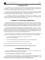
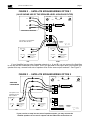
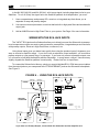
powered subwoofers operation manual MX-SERIES: MX-300, MX-200, MX-125 Mk II, MX-105, MX-70B V-SERIES: V-125, V-75 Mk II, VX-7 Mk II Miller & Kreisel Sound Corporation 10391 Jefferson Boulevard Culver City, CA 90232 USA (310) 204-2854 FAX (310) 202-8782 © 1997 Miller & Kreisel Sound Corp. powered subwoofers page 2 TABLE OF CONTENTS 1. 2. 3. 4. 5. 6. 7. 8. 9. 10. 11. 12. 13. SAFETY INSTRUCTIONS................................................................................3 INTRODUCTION........................................................................................4 WHERE TO LOCATE YOUR SUBWOOFER....................................................4 SUBWOOFER HOOK-UP.................................................................................4 STANDARD AMPLIFIER/SPEAKERWIRE CONNECTIONS........................................5 SATELLITE SPEAKER WIRING OPTION 1...............................................................6 MX-105, MX-70B, V-125, V-75 Mk II, VX-7B SPEAKER-LEVEL HIGH-PASS FILTER........6 SATELLITE SPEAKER WIRING OPTION 2...............................................................6 WIRING WITH THE RCA JACK INPUTS..........................................................................8 WIRINGWITHTHE M&K HP-80 ORVF-80 ELECTRONIC HIGH-PASS FILTERS..............9 PLUGGING IN THE SUBWOOFER..........................................................................9 SATELLITE/SUBWOOFER PHASINGTEST..................................................10 USE OFTHE "LOW PASS FILTER" CONTROL...............................................11 USE OFTHE "BYPASS SWITCH (MX-125 Mk II ONLY)...................................11 USINGTWO SUBWOOFERS.........................................................................11 FINE-TUNING SUBWOOFER PLACEMENT..................................................11 HOMETHEATRE USAGE...............................................................................12 CONNECTING TO A SURROUND SOUND RECEIVER OR PROCESSOR.......................12 SPECIAL INSTALLATION NOTES..................................................................13 TROUBLESHOOTING..............................................................................14 REPLACEMENT FUSEVALUES...........................................................................16 IFYOU NEED SERVICE..................................................................................16 WIRING DIAGRAMS FIGURE 1 FIGURE 2 FIGURE 3 FIGURE 4 TO AN AMPLIFIER USING SPEAKER WIRES.................................5 SATELLITE SPEAKER WIRING OPTION 1......................................7 SATELLITE SPEAKER WIRING OPTION 2......................................7 USING THE PREAMP INPUTS (RCA JACKS)..................................8 powered subwoofers page 3 CAUTION RISK OF ELECTRIC SHOCK DO NOT OPEN The lightning flash with arrowhead, within an equilateral triangle, is intended to alert the user of the presence of uninsulated "dangerous voltage" within the product's enclosure that may be of sufficient magnitude to constitute a risk of electric shock to persons. CAUTION: TO PREVENT THE RISK OF ELECTRIC SHOCK, DO NOT REMOVE COVER (OR BACK). NO USER-SERVICEABLE PARTS INSIDE. REFER SERVICING TO QUALIFIED SERVICE PERSONNEL. The exclamation point within an equilateral triangle is intended to alert the user of the presence of important operating and maintenance (servicing) instructions in the literature accompanying the appliance. 1. SAFETY INSTRUCTIONS 1. READ INSTRUCTIONS - All safety and operating instructions should be read before this product is operated. 2. RETAIN INSTRUCTIONS - The safety and operating instructions should be retained for future reference. 3. HEED WARNINGS - All warnings on this product and in the operating instructions should be adhered to. 4. FOLLOW INSTRUCTIONS - All operating and use instructions should be followed. 5. ATTACHMENTS - Do not use attachments not recommended by the product manufacturer as they may cause hazards. 6. WATER AND MOISTURE - Do not use this product near water - for example, near a bath tub, wash bowl, kitchen sink, or laundry tub; in a wet basement; or near a swimming pool; and the like. 7. ACCESSORIES - Do not place this product on an unstable cart, stand, tripod, bracket, or table. The product may fall, causing serious injury to a child or adult, and serious damage to the product. Use only with accessories recommended by the manufacturer, or sold with the product. Any mounting of the product should follow the manufacturer's instructions and should use a mounting accessory recommended by the manufacturer. 8. POWER SOURCE - This product should be operated only from the type of power source indicated on the marking label. If you are unsure of the type of power supply to your home, consult your product dealer or local power company. 9. OVERLOADING - Do not overload wall outlets or extension cords as this can result in a risk of fire or electric shock. 10. LIQUID ENTRY - Never spill any liquid of any kind on the product. 11. SERVICING - Do not attempt to service this product yourself as opening or removing covers, including those over bottom or side speaker drivers, may expose you to dangerous voltage or other hazards. Refer all service to qualified service personnel. 12. DAMAGE REQUIRING SERVICE - Unplug this product from the wall outlet and refer servicing to qualified personnel under the following conditions: a. When the power-supply cord or plug is damaged. b. If liquid has been spilled, or objects have fallen into this product. c. If the product does not operate normally by following the operating instructions. Adjust only controls that are covered by the operating instructions as an improper adjustment of other controls may result in damage and will often require extensive work by a qualified technician to restore the product to its normal operation. d. If the product has been dropped or damaged in any way. e. When the product exhibits a distinct change in performance - this indicates a need for service. 13. REPLACEMENT PARTS - When replacement parts are required, be sure the service technician has used replacement parts specified by the manufacturer or have the same characteristics as the original part. Unauthorized substitutions may result in risk of fire, electric shock, or other hazard. 14. SAFETY CHECK - Upon completion of any service or repairs to this product, ask the service technician to perform safety checks to determine that the product is in proper operating condition. 15. HEAT - This product should be situated away from heat sources such as radiators, heat registers, stoves, or other products (including amplifiers) that produce heat. powered subwoofers page 4 2. INTRODUCTION Congratulations! You have just made perhaps the most exciting and dramatic addition that you could make to your audio or audio/video system. The new dimension of deep and powerful bass provided by your M&K Deep Bass Powered Subwoofer will thrill and excite you. We encourage you to read this owner's manual, as there is a great deal of information provided here to help you get the best possible performance. This manual gives you basic hook-up instructions first, followed by more detailed technical, installation, and service information. If you have any questions about your Subwoofer, please contact your M&K dealer, or call us directly at (310) 204-2854, from 8:30 AM to 5:00 PM Pacific Time. We will be more than happy to help you with any question, no matter how simple or complex it may be. 3. WHERE TO LOCATE YOUR SUBWOOFER M&K Subwoofers will perform well in just about any room location. In fact, unless your ear is within a couple feet of the Subwoofer, the deep bass will seem to come exclusively from your Satellite speakers. (By Satellite speakers, we mean the main speakers used with your Subwoofer). There is no need to place your Subwoofer between the Satellite speakers or in any specific location in the room. Except for the V-125, M&K Subwoofers are not magnetically shielded. Leave 2 - 3 feet of clearance around any television set. This shielding avoids magnetization of the shadow mask of the television's picture tube, which will distort the television's picture. If this ever happens to your set, turn it off and on a few times to use the set's built-in degaussing circuitry. If the problem persists, contact a TV technician and ask him or her to use an external degaussing coil. No matter where you put the Subwoofer, you must allow room for ventilation of its heatsink and backplate. The Subwoofer's power amplifier is mounted on the backplate, and it generates heat. 1. Do not place the Subwoofer against a wall. Leave at least one foot clearance around the heatsink. 2. Do not place the Subwoofer near baseboard heaters or forced air heating outlets. 3. Do not use the Subwoofer outdoors or in a humid environment. For more detailed placement information, please see Section 8, on page 12. Do not plug the Subwoofer into an AC outlet until all system wiring is complete. 4. SUBWOOFER HOOK-UP There are two different ways to connect the Subwoofer to your system. One uses speaker wire, and the other uses interconnect cable with RCA-type jacks. Read this section before deciding which is best for your system. Look at the back panel of the Subwoofer. You will see two RCA input jacks labelled "INPUT" and two sets of speaker wire input terminals labelled "FROM AMPLIFIER" and "TO SPEAKERS." You must choose to use either the speaker wire inputs or the RCA jack inputs. powered subwoofers page 5 STANDARD AMPLIFIER/SPEAKER WIRE CONNECTIONS Many M&K subwoofer owners hook up their Subwoofer by connecting it to their receiver or amplifier using speaker wires. To do so, you make the same kind of connections that you would use for your Satellite (or main) speakers, except that both the left and right channels go to the Subwoofer. (If you are using two Subwoofers, connect one channel only to each Subwoofer). NOTE: You cannot connect the MX-125 Mk II using speaker wires. If you have to connect an MX-125 Mk II to an amplifier or receiver does not have RCA outputs, please contact your dealer or the M&K factory. We offer an optional RM-2 High Level to Low Level convertor with Remote Volume Control, which will allow you to drive the MX-125 Mk II with speaker-level amplifier outputs. 1. 2. Run speaker wire between the Amplifier's Left channel output terminals and the Subwoofer's Left channel "FROM AMPLIFIER" terminals. a. Connect the Amplifier's Left channel Positive (+) terminal and the Subwoofer's Left RED (+) "FROM AMPLIFIER" terminal. b. Connect the Amplifier's Left channel Negative ( — ) terminal and the Subwoofer's Left BLACK ( — ) "FROM AMPLIFIER" terminal. Make matching connections for the Right channel. See Figure 1. FIGURE 1 - TO AN AMPLIFIER USING SPEAKER WIRES LOW PASS FILTER 75 (Hz) L LEFT/MONO BASS LEVEL RIGHT + 100 60 50 125 FROM PREAMP PHASE MIN MAX LEFT AVIS: RISQUE DE CHOC ELECTRIQUE. NE PAS OUVRIR. RIGHT R FROM AMPLIFIER CAUTION RISK OF ELECTRIC SHOCK DO NOT OPEN This option is not available with the MX-125 Mk II RIGHT LEFT TO SPEAKERS AMPLIFIER OR RECEIVER ATTENTION: Made in U.S.A. DEBRANCHER AVANT DE REMPLACER LE FUSIBLE. UTILIZER UN FUSIBLE DE RECHANGE DE MEME TYPE. MILLER & KREISEL SOUND CORPORATION 10391 Jefferson Blvd, Culver City, CA 90232 310/204-2854 CAUTION: DISCONNECT SUPPLY CORD BEFORE CHANGING FUSE. REPLACE FUSE ONLY WITH SAME TYPE. 120 VAC 50/60 Hz T 4 AMP SLOW-BLOW IMPORTANT NOTE FOR DOLBY SURROUND SOUND SYSTEMS: When the Subwoofer is connected to the Left and Right amplifier outputs, and the controller is in Pro-Logic mode, the Center channel WIDE/NORMAL switch MUST be set to the NORMAL mode. If the switch is set to the WIDE mode, the bass content of the Center channel will not be fed to the Subwoofer, and a significant amount of bass in the program material will not be reproduced. powered subwoofers page 6 You now have two options for connecting your Satellite speakers. SATELLITE SPEAKER WIRING OPTION 1 NOTE: For the MX-105, MX-70B, V-125, V-75 Mk II, or VX-7 Mk II, see below. With this option, you connect the wiring for the Satellites directly to the Subwoofer. There is no performance advantage with this method, but it may require less speaker wire and be more convenient. 1. 2. Run speaker wire between the Subwoofer's Left channel output terminals and the Left Satellite speaker. a. Connect the Subwoofer's RED (+) "TO SPEAKERS" terminal to the Positive (+) terminal on the back of the Left Satellite speaker. b. Connect the Subwoofer's Left BLACK ( — ) "TO SPEAKERS" terminals to the Negative ( — ) terminal on the back of the Left Satellite speaker. Make matching connections to the Right channel Satellite speaker. See Figure 2. SPEAKER-LEVEL HIGH-PASS FILTER (MX-105, MX-70B, V-125, V-75 Mk II, VX-7 Mk II) The MX-105, MX-70B, V-125, V-75 Mk II, and MX-7 Mk II have a speaker-level high-pass filter (other M&K models do not). When Satellite speakers are connected to the "TO SPEAKER" terminals on these subwoofers, the low bass frequencies below 80 Hz are filtered from the Satellite speakers. This filter significantly reduces the bass demand placed on your main speakers and can make a noticeable improvement in their sound quality, especially in the midbass and lower midrange. The filter may make other subtle changes to the sound quality, however, so you may want to experiment with and without the filter to determine the best configuration for your system. To use the filter, connect the speaker wire from the left and right channels of your amplifier to the "FROM AMPLIFIER" terminals on the subwoofer. Connect your left and right main speakers to the "TO SPEAKERS (SPEAKER LEVEL HIGH PASS)" terminals on the subwoofer. See Figure 2. If you have a Dolby Pro-Logic system, we recommend that you set the CENTER CHANNEL switch on the Dolby processor or receiver to the NORMAL mode. This provides a low bass filter for the center channel speaker and also insures that the bass from all three front channels is fed to the subwoofer. The high-pass filter is bypassed when the subwoofer is connected with RCA interconnect cable. SATELLITE SPEAKER WIRING OPTION 2 This option connects the Satellite speakers direct to your amp or receiver. It requires two sets of speaker wires — one set running to the Satellite speakers and the other set to the Subwoofer. There is no High-Pass filter with ANY M&K subwoofer using this option. Connect the Satellite speakers to your Amplifier, using the same amplifier output terminals as the Subwoofer. Do not connect the Satellite speakers to the Subwoofer. powered subwoofers page 7 FIGURE 2 - SATELLITE SPEAKER WIRING OPTION 1 (ALSO SHOWS USE OF THE SPEAKER-LEVEL HIGH-PASS FILTER) LOW PASS FILTER 75 (Hz) L LEFT/MONO BASS LEVEL RIGHT + 100 60 50 FROM PREAMP PHASE 125 MIN MAX LEFT RISK OF ELECTRIC SHOCK DO NOT OPEN AVIS: RISQUE DE CHOC ELECTRIQUE. NE PAS OUVRIR. RIGHT FROM AMPLIFIER CAUTION R This option is not available with the MX-125 Mk II RIGHT LEFT TO SPEAKERS (SPEAKER LEVEL HIGH-PASS FILTER) AMPLIFIER OR RECEIVER CAUTION: ATTENTION: DISCONNECT SUPPLY CORD BEFORE CHANGING FUSE. REPLACE FUSE ONLY WITH SAME TYPE. DEBRANCHER AVANT DE REMPLACER LE FUSIBLE. UTILIZER UN FUSIBLE DE RECHANGE DE MEME TYPE. Made in U.S.A. 120 VAC 50/60 Hz MILLER & KREISEL SOUND CORPORATION 10391 Jefferson Blvd, Culver City, CA 90232 310/204-2854 MIDRANGE CONTOUR MIDRANGE CONTOUR MID EFFICIENCY NORMAL INPUT TREBLE CONTOUR MID TWEETER LOW TWEETER MID EFFICIENCY NORMAL 4 ohms LOW EFFICIENCY NORMAL T 4 AMP SLOW-BLOW INPUT 4 ohms LOW EFFICIENCY SATELLITE SPEAKER TREBLE CONTOUR MILLER & KREISEL SOUND CORPORATION MID TWEETER NORMAL 10391 Jefferson Boulevard., Culver City, CA 90232 Voice (310) 204-2854 Fax (310) 202-8782 LOW TWEETER MADE IN USA SATELLITE SPEAKER MILLER & KREISEL SOUND CORPORATION 10391 Jefferson Boulevard., Culver City, CA 90232 Voice (310) 204-2854 Fax (310) 202-8782 MADE IN USA LEFT RIGHT If your Amplifier has two sets of speaker outputs (e.g., A and B), you can connect the Satellites to one set and the Subwoofer to the other. But if you get weak or no output when you connect your speaker this way, connect both sets of speaker wires to the same output terminals. See Figure 3. FIGURE 3 - SATELLITE SPEAKER WIRING OPTION 2 LOW PASS FILTER 75 (Hz) L LEFT/MONO BASS LEVEL RIGHT + 100 60 50 125 AMPLIFIER OR RECEIVER FROM PREAMP PHASE MIN LEFT R AVIS: RISQUE DE CHOC ELECTRIQUE. NE PAS OUVRIR. RIGHT FROM AMPLIFIER CAUTION RISK OF ELECTRIC SHOCK DO NOT OPEN INPUT 4 ohms LOW EFFICIENCY TREBLE CONTOUR MID TWEETER NORMAL LOW TWEETER SATELLITE SPEAKER MILLER & KREISEL SOUND CORPORATION 10391 Jefferson Boulevard., Culver City, CA 90232 Voice (310) 204-2854 Fax (310) 202-8782 MADE IN USA MID EFFICIENCY NORMAL INPUT 4 ohms LOW EFFICIENCY TREBLE CONTOUR MID TWEETER NORMAL LOW TWEETER SATELLITE SPEAKER TO SPEAKERS MIDRANGE CONTOUR MID EFFICIENCY NORMAL LEFT MIDRANGE CONTOUR RIGHT This option is not available with the MX-125 Mk II MILLER & KREISEL SOUND CORPORATION ATTENTION: 10391 Jefferson Boulevard., Culver City, CA 90232 Voice (310) 204-2854 Fax (310) 202-8782 MADE IN USA Made in U.S.A. DEBRANCHER AVANT DE REMPLACER LE FUSIBLE. UTILIZER UN FUSIBLE DE RECHANGE DE MEME TYPE. MILLER & KREISEL SOUND CORPORATION LEFT RIGHT CAUTION: DISCONNECT SUPPLY CORD BEFORE CHANGING FUSE. REPLACE FUSE ONLY WITH SAME TYPE. 120 VAC 50/60 Hz 10391 Jefferson Blvd, Culver City, CA 90232 310/204-2854 If your receiver or amp has two sets of speaker outputs, you may connect the Satellite speakers to one set of outputs and the Subwoofer to the other set. T 4 AMP SLOW-BLOW MAX powered subwoofers page 8 In the MX-300, MX-200, and MX-125 Mk II, a full-range signal (including deep bass) is fed to your Satellites. To roll off (filter) the signal fed to the Satellite speakers for biamplification, you must: 1. Have a separate amp and preamp OR a receiver or integrated amp that allows you to separate its amp and preamp stages. 2. Use a surround sound processor or receiver that has built-in high-pass filters and a subwoofer output jack. 3. Add an M&K Electronic High-Pass Filter to your system. See Page 9 for more information. WIRING WITH THE RCA JACK INPUTS The "INPUT" RCA jacks on the Subwoofer allow you to directly connect the Subwoofer to preamplevel components such as surround sound processors, preamplifiers, integrated amps and receivers with preamp outputs, Electronic High-Pass filters, crossovers, etc. Using these inputs gives you better bass quality than using the speaker inputs (it bypasses your amp or receiver's amplifier stage). If you don't have a subwoofer output available, you must have preamp outputs on your preamp, amp, or processor. If you have only one set of preamp outputs, use a Y-connector to feed both the amplifier and the Subwoofer. In many cases, using a Y-connector may slightly degrade the Satellite speakers' sound quality. Please feel free to experiment. To connect the Subwoofer in this way, simply run a set of shielded RCA - RCA interconnect cables from the output jacks on your component to the "FROM PREAMP" jacks on the Subwoofer's backplate. See Figure 4. FIGURE 4 - USING THE RCA JACK INPUTS LOW PASS FILTER 75 (Hz) MAIN OUT 2 MAIN OUT 1 PREAMP LEFT RIGHT 60 RIGHT LEFT LEFT/MONO BASS LEVEL RIGHT + 100 50 125 FROM PREAMP PHASE MIN MAX LEFT MAIN INPUT RIGHT TO SPEAKERS AMPLIFIER OR RECEIVER R RIGHT LEFT LEFT L ATTENTION: Made in U.S.A. DEBRANCHER AVANT DE REMPLACER LE FUSIBLE. UTILIZER UN FUSIBLE DE RECHANGE DE MEME TYPE. MILLER & KREISEL SOUND CORPORATION 10391 Jefferson Blvd, Culver City, CA 90232 310/204-2854 MIDRANGE CONTOUR INPUT 4 ohms LOW EFFICIENCY TREBLE CONTOUR MID TWEETER NORMAL LOW TWEETER CAUTION: DISCONNECT SUPPLY CORD BEFORE CHANGING FUSE. REPLACE FUSE ONLY WITH SAME TYPE. 120 VAC 50/60 Hz T 4 AMP SLOW-BLOW MIDRANGE CONTOUR MID EFFICIENCY NORMAL NE PAS OUVRIR. RIGHT FROM AMPLIFIER CAUTION RISK OF ELECTRIC SHOCK DO NOT OPEN AVIS: RISQUE DE CHOC ELECTRIQUE. SATELLITE SPEAKER MILLER & KREISEL SOUND CORPORATION 10391 Jefferson Boulevard., Culver City, CA 90232 Voice (310) 204-2854 Fax (310) 202-8782 MADE IN USA LEFT MID EFFICIENCY NORMAL INPUT 4 ohms LOW EFFICIENCY TREBLE CONTOUR MID TWEETER NORMAL LOW TWEETER SATELLITE SPEAKER MILLER & KREISEL SOUND CORPORATION 10391 Jefferson Boulevard., Culver City, CA 90232 Voice (310) 204-2854 Fax (310) 202-8782 MADE IN USA RIGHT If you have one Preamp Output, connect both the Subwoofer and the Amplifier to it. powered subwoofers page 9 If you are using two Subwoofers, run the left channel interconnect cable to the left Subwoofer and the right channel cable to the right Subwoofer. USING THE HP-80 OR VF-80 ELECTRONIC HIGH-PASS FILTERS The M&K HP-80 and VF-80 Electronic High-Pass Filters can improve the performance of any system that allows for separation of its preamp and power amp stages by filtering the bass signal fed to the main amplifier and Satellite speakers. To use these filters with an integrated amp or receiver, the amp or receiver MUST have back panel RCA jacks labelled Preamp/Main Output AND Power Amp/Main Input. There may be a switch or jumper connections between them. If you have a multichannel surround sound system, we offer both 2 and 3 channel versions of each filter. Remember that to use these filters, your component must have both a preamp-type output and a power amp input. The 3 channel VF-80 and HP-80 can only be used if your component has a dedicated subwoofer output jack. If your component has its own high or low-pass filters, they should be turned off when using the VF-80 or HP-80. Do not run your system with multiple filters. If your receiver or controller is THXcertified, you do not need these filters. All THX controllers and receivers have the proper high and lowpass filters built in. These filters will give you greater dynamic range, lower distortion, and an increased maximum output level. If you have any questions about the suitability of your components, please contact your M&K dealer or the factory. PLUGGING IN THE SUBWOOFER Once all the speaker wires or preamp interconnect cables are in place, you are ready to plug in the Subwoofer. Set the "BASS LEVEL" control to "MIN". Then plug the AC cord in. You should hear a thump from the Subwoofer. This is the normal sound of its power supply charging and discharging when it is plugged in and unplugged. Once your system wiring is complete and the Subwoofer is plugged into the wall, leave it plugged in, even when the system is turned off. The normal mode of operation for the Subwoofer is to remain plugged in 24 hours a day. Among other things, this means that you don't have to walk over to the Subwoofer to turn it on every time you want to use the system. If you decide to plug the Subwoofer into a switched outlet on another component, that outlet must have the following minimum power ratings: Minimum of 200 watts: V-75 Mk II, VX-7 Mk II Minimum of 300 watts: MX-105, MX-125 Mk II, MX-70B, V-125 Do not use a switched outlet with the MX-300 and MX-200. Now, play some music through your system to make sure that the Satellite speakers are working properly. If they are, carefully advance the "BASS LEVEL" control. The Subwoofer should begin to powered subwoofers page 10 play. Set the "BASS LEVEL" control where the Subwoofer sounds in balance with the Satellite speakers. If the system is not working properly, unplug the Subwoofer and check all of your connections. Call your dealer or the factory if you cannot solve any problem. The best way to set the level of the Subwoofer is to do it by ear, listening over several hours or days to familiar recordings. Make adjustments to the level in small increments, depending on whether the bass level sounds too high or too low. Of course, you can always deliberately set the level higher or lower than flat if you need a higher bass level or if you don't want to disturb your neighbors. 5. SATELLITE/SUBWOOFER PHASING TEST You are now almost finished with the basic set-up. But before you can sit down to enjoy your new Subwoofer, you need to perform one simple Phasing Test. This test insures optimum sound in the critical bass frequencies where your Subwoofer and Satellite speakers overlap. Play a familiar CD, LP, or tape with steady, consistent bass. Listen carefully to the mid-bass (75 - 125 Hz) region — the part of the spectrum where electric or string basses and drums are found. Then, move the "PHASE" switch on the SUBWOOFER's back panel from either up (+) or down (—) to the opposite position. Now listen to the same musical passage, concentrating on the mid-bass region. If you hear less bass, the original connections were correct. If you hear more bass, the new connections are correct. If you have two Subwoofers, perform one test for each Subwoofer. When you perform each test, make sure the other Subwoofer is not operating by either unplugging its input cable or its power cord. SPECIAL INSTRUCTIONS FOR THE VX-7 Mk II: The VX-7 Mk II does not have a back panel "PHASE" switch. Therefore, to check phase, follow these instructions: Instead of moving the switch's position, you must reverse the Positive and Negative speaker inputs on the back of BOTH Satellite speakers. Move the lead on the Positive (+) terminal to the Negative (—) terminal, and vice versa. You can also do this at the subwoofer's "TO SPEAKERS" terminals, but never switch the inputs at both the backs of the Satellite speakers and the Subwoofer. Another method of setting phase uses a pink noise source and a spectrum analyzer. If you have these, place the microphone at the main listening position and look at its display in the mid-bass region of 70 - 125 Hz. The wiring/ switch position showing the most output in that region has the correct phase. You need to perform this test because when Satellite speakers are located separate from a Subwoofer, each speaker is at a different distance from your ear. In some cases, the difference will be just enough so that the output from the Subwoofer arrives out of phase with the output of the Satellites. When this happens, that critical mid-bass is actually cancelled. You should re-do this test any time you move your speakers. If you want to experiment further, you can move the Satellite speakers either towards or away from your listening position, making changes in small increments. This will focus the system's sound to its optimum. When you hear the best balance between stereo image localization and maximum impact and output in the mid-bass, you have the ideal location. powered subwoofers page 11 6. USE OF THE "LOW PASS FILTER" CONTROL The back panel control "LOW PASS FILTER" sets the upper rolloff point of the Subwoofer, eliminating mid-bass and midrange that are being reproduced by your Satellite speakers. The control is a means of fine-tuning the transition between your Subwoofer and Satellite speakers, and it provides a rolloff of 18 dB/octave up to 125 Hz, where the filter shifts to 36 dB/octave. In most systems, including M&K Satellites, 85 Hz gives the best blend. If you don't want to experiment, set the control at 85 Hz. The goal is to get a balanced acoustic output in your room. This is not necessarily the same as flat electrical output. Rooms typically reinforce bass frequencies around 100 Hz, so by leaving an electrical gap, you may actually get a smooth acoustical response where it matters, in the room. Think of this control as a mid-bass fine tuning adjustment that you set to achieve the best transition between the Satellite speakers and the Subwoofer. When you hear a smooth sound overall, well balanced between the deep bass and the rest of the audible spectrum, the control is set properly. 7. USE OF THE "BYPASS" SWITCH (MX-125 Mk II ONLY) If you have a THX or non-THX Dolby Digital component with a built-in Low-Pass filter as part of its subwoofer output, or if you are using a separate Electronic Crossover, set the “VARIABLE” / “BYPASS” switch on the back of the MX-125 Mark II to the “BYPASS” position. This bypasses the internal low-pass of the MX-125 Mark II so that there is no interaction between the subwoofer’s filter and your component’s filter. If you have any questions regarding the filters, please contact your M&K dealer or the M&K factory. 8. USING MULTIPLE SUBWOOFERS Using two (or more) subwoofers in your system gives you the ultimate in bass performance. You'll hear improved impact and definition, as well as greater output and dynamic range. If the Subwoofers are located in different parts of the room, you will hear a much smoother bass response, as the room modes excited by one woofer are effectively reduced by the presence of the other. With two Subwoofers, simply run one speaker wire or interconnect to each Subwoofer. Because the left and right channel input signals are combined in the Subwoofer's input stage, the only thing this changes is amplifier gain. To compensate, just set the "BASS LEVEL" control slightly higher. 9. FINE-TUNING SUBWOOFER PLACEMENT If you have the physical space in your room and the interest to experiment with the placement of your Subwoofer, you may be able to even further optimize its sound by moving its location. If you want to do this, listen to the Subwoofer after it is hooked up, using a familiar CD, LP, Laserdisc, or tape with good bass content. After you move the subwoofer from one location to another, listen again, paying attention to the changes in the amount and quality of bass reproduction. Ultimately, the amount and quality of bass you get in your room are dependent on the room itself. Low frequency bass sounds are affected most by the size of the room and the method of construction used to build it. All rooms are different when it comes to reproducing bass, and in any given room, bass quantity and quality changes when the Subwoofer is moved from one location to another. powered subwoofers page 12 A simple rule to remember is that you get more bass when you move the Subwoofer towards any wall or corner. Moving it away from a wall or corner gives you less bass. Remember that the floor also loads the Subwoofer, and that maximum bass is found with the woofer on the floor in a corner. The Subwoofer will probably sound its best when it is on the floor, within a foot or two of one wall, either in or within a few feet of a corner. This provides for good loading to the room, and is the best place to start when experimenting. In some rooms, a corner location may excite resonance modes, resulting in a muddy or boomy sound. In these rooms, a more central location along a wall, away from the corner, may give better results. If you experiment, try to find a spot where no bass notes seem to overpower others and the overall sound is powerful and clean. The goal is to achieve a smooth sound quality, with the entire bass spectrum equally prominent. In most rooms, this will be along one of the room walls, probably close to a corner (or directly in the corner), rather than in the center of the room. Because the Subwoofer generates a great deal of energy, its output may vibrate objects close to it. If you hear such vibration, you may want to move the Subwoofer or act to damp the vibration of nearby objects. For those interested, one Subwoofer is sufficient in a stereo system because of the nature of human hearing. The ear-brain hearing system is unable to locate the direction of bass sounds below approximately 150 Hz. The direction of low frequency sounds (drums, basses, etc.) is determined by the higher frequency overtones and harmonics that are reproduced by the Satellite speakers. All M&K Powered Subwoofers have exceptionally sharp (36 dB/octave) low-pass filters to remove the midbass and midrange frequencies unwanted in a Subwoofer. This makes your M&K Subwoofer truly non-directional. We realize that you are not going to design your room around the Subwoofer. Use these suggestions as guidelines, remembering that the Subwoofer will work well just about anywhere in the room. This section is intended to help you find a good balance between sound quality and aesthetics. 10. HOME THEATRE USAGE If you are using your Subwoofer in a Home Theatre system, set-up is essentially the same as for a music system, so all of the previous instructions apply. In some cases, however, you may prefer the subwoofer set to a higher playback level for video sources. This may occur when video sources (especially older films and some television) have very little deep bass present. You may also want to exaggerate the effect to make spectacular video sources even more impressive! When your subwoofer is going to be located close to a television set, remember to leave 2 - 3 feet of clearance between the television and subwoofer, unless the subwoofer is magnetically shielded (V-125 only). CONNECTING THE SUBWOOFER TO A SURROUND SOUND RECEIVER OR PROCESSOR: The preferred connection from a surround sound amp or controller is from a SUBWOOFER OUTPUT (or MONO) RCA jack. This connection usually insures that a full bass signal is fed to the subwoofer. If your component doesn't have a subwoofer output jack, connect the Subwoofer to the powered subwoofers page 13 front Left and Right channel speaker outputs (do not use the Center channel speaker output). VERY IMPORTANT: When the Subwoofer is connected to the Left and Right amplifier outputs (this means using speaker wires), and the controller is in Pro-Logic mode, the Center channel WIDE/ NORMAL switch MUST be set to the NORMAL mode. If the switch is set to the WIDE mode, the bass content of the Center channel will not be fed to the Subwoofer, and a significant amount of the bass in the material you are listening to will be lost. 11. SPECIAL INSTALLATION NOTES MX-300, MX-200, MX-125 Mk II, MX-105: An enclosed hardware kit contains four black metal spikes, threaded at one end and tapering to a sharp point at the other. Depending on their orientation, they can be used either as spikes or rubber feet. Do not use the spiked feet on hardwood or tile floors. They can damage the floor surface. By mounting these spikes into the threaded inserts mounted in the bottom of the Subwoofer, you can elevate the Subwoofer, and on carpet, couple it more tightly to that floor. On hardwood, tile, or concrete, the spikes should be inverted, with the point mounted facing into the cabinet. One of the black rubber feet provided should then be pressed over the exposed flat end of the foot. The threaded inserts are found in the four corners of the cabinet's bottom. The MX-300 has a fifth insert, which allows you to use three of the five in a triangular pattern. The inserts are 1/4 - 20, that is, 1/4 inch in diameter and 20 threads per inch. This is compatible with the most spikes, "cones," "tiptoes," etc. offered by manufacturers of specialized speaker feet. To properly secure the feet to the cabinet, you must use the provided washer and jamb nut on the threaded portion of the foot. The washer goes first, with the nut over it, holding the washer securely in place. This prevents damage to the spike and the threaded insert in case something moves the cabinet sideways. MX-200, MX-145, MX-125 Mk II, MX-105, MX-70B: Because your M&K MX-series Subwoofer uses an inverted driver that fires down into the floor, it loads differently to the room than a conventional speaker or forward-firing Subwoofer. This means that you may want to experiment a bit more with its placement and setup to get optimum sound quality. 1. Because of its downward-firing driver, your MX Subwoofer may be more susceptible to producing a boomy sound if it is located in a corner. Always try the subwoofer first in a corner. If it sounds boomy, move it a few feet out of the corner. 2. While your Subwoofer performs perfectly well directly on the floor, the distortion cancellation of its push-pull design and its frequency response are best when the Subwoofer is slightly elevated. We therefore recommend that you use the enclosed feet to raise the subwoofer off the floor. 3. Read Section 6 (page 11), Use of the LOW PASS FILTER Control, carefully. The setting of this control is more critical with your MX model Subwoofer. With these models it is more likely that you will find the optimum setting to be slightly below the 85 Hz recommended for other models. powered subwoofers page 14 MX-70B: The MX-70B gives a very high level of performance in a compact cabinet. Therefore, it is likely to be installed in both vertical and horizontal locations. To avoid having its inverted driver exposed in installations where the cabinet is horizontal, the MX-70B has two speaker grills. If your MX-70B has a solid grille over the inverted driver, leave this grille in place. The MX-70B is designed so that the sound eminating from this driver comes from the opening in the front baffle. The solid grille cover insures that this is the case. 12. TROUBLESHOOTING Your M&K Subwoofer amplifier circuit provides high reliability, and, if necessary, easy modular replacement of parts. This guide will help you to solve or diagnose most problems that can occur with your Subwoofer. In the event that a fuse blows, you must replace it with a fuse of the correct value to avoid a fire hazard and to maintain your warranty protection. 1. If your Subwoofer has no output: a. Make sure that the Subwoofer is plugged into an AC outlet. b. Check the "BASS LEVEL" control and make sure that it is set above the "MIN" position. Rotate it clockwise if it is set to the "MIN" position. c. Check the red LED on the Subwoofer's back panel. If the LED is not lit, check the AC fuse next to the LED. Unplug the Subwoofer before changing the fuse. See instructions on Page 16. If the element inside the . fuse is broken, replace the fuse. If it blows again, contact your dealer or M&K. d. If the red LED is lit, try this test: Turn the "BASS LEVEL" control to "MIN". Plug a standard RCA cable into the "FROM PREAMP" jacks. Lightly touch the plug at the free end of the cable, while slowly turning the "BASS LEVEL" control clockwise. If you hear noise from the Subwoofer when you touch the cable, the Subwoofer is functioning. Look elsewhere in your system for the problem. If you hear no noise, contact your dealer or M&K. e. Make sure that the input cables are OK. Double check your connections. If necessary, replace any defective cables or speaker wires. 2. If, after operating the woofer at high volume levels for a long time, the woofer cuts out or becomes intermittent: Your Subwoofer has a protection circuit that protects it from overheating. After hours of continuous operation at extremely high volume levels, this circuit may kill the power to the Subwoofer. When it activates, the sound may switch in and out rapidly, with a fluttering sound. If this happens, unplug the unit and let it sit for at least half an hour. After that time, plug it back in. It should operate normally. If you find this happens frequently, contact the factory for advice. 3. If you are using the "FROM AMPLIFIER" terminals, and the Subwoofer has very little output: powered subwoofers page 15 Make sure that the input cables are in phase. Reverse the (+) and the ( — ) connections for ONE CHANNEL ONLY at the "FROM AMPLIFIER" terminals. If the problem remains, put the cables back as they were. Then perform the test in Step 4. 4. If the midbass range (the area of transition between Subwoofer and Satellite speakers) sounds weak: Refer to Section 5, Phasing Test, on page 10. Reverse the (+) and ( — ) connections at the back of BOTH Satellite speakers, OR switch the "PHASE" switch from (+) to ( — ) or vice versa. The wiring configuration that gives the most bass is correct. 5. If you are using the "FROM PREAMP" input terminals, and you hear a thump through the Subwoofer every time you turn the system on: Either the preamp, receiver, or surround sound processor is generating the thump, and the Subwoofer is reproducing it. To eliminate this problem, switch to the speaker wire "FROM AMPLIFIER" input terminals. 6. If you hear a persistent hum or buzz through the Subwoofer: Because the Subwoofer reproduces the 60 Hz hum frequency, it is often blamed for causing hum that originates elsewhere in the system. Always avoid running all speaker wires and RCA interconnect cables near to AC cords and component power supplies. Wires and cables running close to AC lines are a common source of hum. If necessary, reroute your cables. To identify the source of hum, remove all input cables to the Subwoofer, but leave it plugged into the AC outlet. Carefully turn the "BASS LEVEL" control up towards the "MAX" position. If you hear hum coming from the Subwoofer's speaker driver, the Subwoofer is the source of the hum. If you hear no hum or less hum, the problem is probably coming from another component. Hum can also be caused by AC ground loops. If the Subwoofer is plugged into a separate AC outlet, try plugging it into the same outlet used for your amplifier or receiver, or reverse the polarity of its AC plug. If these suggestions do not solve your problems, contact your dealer or M&K. 7. If there is an unusual sound coming from the Subwoofer with no music playing: Try removing the input cables as described in Step 5 above. If the noise disappears, it is coming from another component. If it does not go away, contact your M&K dealer or the factory. powered subwoofers page 16 IF YOU NEED TO REPLACE THE EXTERNAL FUSE: Disconnect supply cord before changing fuse. Replace fuse only with same type. Remove the fuse cap. If the fuse cap has an arrow printed on it, push the cap in and turn it counterclockwise. If the fuse cap has a slot in it, use a flat head screwdriver to turn it counterclockwise. Look carefully at the fuse. If the wire filament inside the glass is broken, replace the fuse ONLY with one of the identical size and value. Using a fuse of a larger value will void your warranty AND MAY CREATE A FIRE HAZARD. Plug the Subwoofer back in. If it does not work, unplug it immediately, and contact your dealer or M&K for service. REPLACEMENT FUSE VALUES (units with U.S. standard fuses) Replace only with same type 3AG-250 VAC SLO-BLO 1 1/4" x 1/4" fuse. MODEL MX-2000 MX-200 MX-125 Mk II MX-105 MX-80 V-100 V-90 110 v 6 amp 4 amp 4 amp 2.5 amp 1.25 amp 4 amp 1.25 amp 220 v 3 amp 2 amp 2 amp 1.25 amp .75 amp 2 amp .75 amp MODEL MX-300 MX-145 MX-100 MX-90 MX-70/MX-70B V-125 V-75/V-75 Mk II 110 v 6 amp 2.5 amp 4 amp 2 amp 2 amp 2 amp 1.25 amp 220 v 3 amp 1.25 amp 2 amp 1 amp 1 amp 1 amp .75 amp V-3B 1.25 amp .75 amp VX-4 1 amp .75 amp VX-7B/VX-7 Mk II 1 amp .75 amp REPLACEMENT FUSE VALUES (units with IEC 127-2/III standard fuses) Replace only with same type IEC 127-2/III 5 X 20 mm timelag "T" fuse. MODEL MX-2000 MX-145 MX-105 MX-70/70B V-90 VX-4 220 v 2.5 A 1A 1A 800 ma 630 ma 630 ma MODEL MX-300 MX-125 MX-90 V-100 V-75/V-75 Mk II VX-7/7B/Mk II 220 v 2.5 A 1.6 A 800 ma 1.6 A 630 ma 630 ma MODEL MX-200 MX-100 MX-80 V-125 V-3B 220 v 1.6 A 1.6 A 630 ma 800 ma 630 ma 13. IF YOU NEED SERVICE Contact your dealer or M&K. Please have the unit's model and serial numbers (found on the back of the cabinet), date of purchase, the name of your dealer, and a complete description of the problem. You can call M&K between 8:30 AM and 5:00 PM Pacific Time, Monday through Friday, at (310) 2042854. If you call outside these hours, leave a message, and we will return your call. DO NOT RETURN YOUR SPEAKERS TO THE FACTORY FOR SERVICE WITHOUT OBTAINING PRIOR AUTHORIZATION. All M&K powered subwoofers carry a three year limited parts and labor warranty. This warranty is transferable to subsequent owners up to three years from the date of original purchase, and it includes subwoofer amplifiers. It does not cover abuse, misuse, repairs by unauthorized service stations, speakers without serial numbers, and speakers damaged in shipping or by accident. If you have any questions about the warranty, please contact M&K. rev 15.0897