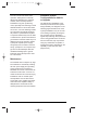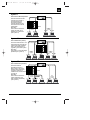
1
JBL 1394 Manual
7/17/98 11:49 AM
Page 1
G T S 1 0 0
GTS100
2/1 CHANNEL AUTOMOTIVE POWER AMPLIFIER
OWNER’S MANUAL
JBL 1394 Manual
7/17/98 11:49 AM
Page 2
Table Of Contents
Introduction ..................................................................................................3
Features.......................................................................................................4
About Installation .........................................................................................4
Quick Start ...................................................................................................5
System Design Using the GTS100 ..............................................................6
Typical Applications .....................................................................................7
Installation Precautions................................................................................9
Physical Installation .....................................................................................9
Controls and Connectors ...........................................................................10
Mounting Instructions.................................................................................12
Wiring.........................................................................................................12
Power Supply Connections........................................................................14
Audio Input Connections............................................................................15
Speaker Connections ................................................................................17
Operation ...................................................................................................20
Solving Noise Problems.............................................................................21
Maintenance ..............................................................................................24
Additional System Configurations for Add-On or Upgrade ........................24
In Case of Difficulty ....................................................................................27
Specifications.............................................................................................29
Owner’s Warranty Information Records
Model Number
Serial Number
Dealer Name
City, State, Zip
Sales Receipt Number
Date of Purchase
JBL 1394 Manual
7/17/98 11:49 AM
Page 3
Introduction
Thanks for purchasing your new
GT series automotive amplifier. The
GT series amplifier you have chosen
includes many unique features to
enhance its performance and utility.
The power amplifier circuitry is a
fully discrete design notable for low
distortion and unusually clean and clear
reproduction quality. Your GT series
amplifier will easily connect to virtually
any car audio system, whether it is
factory installed or purchased
separately.
In addition to conventional preamp-level
inputs, this model features JBL’s
Universal Interface design, which facilitates simple connection to factory
radios with the low distortion that is usually only associated with preamp level
connection. With Universal Interface, a
factory radio can be used either as the
main music source or combined with a
CD changer which includes volume
control capability, simultaneously
connected directly to the amplifier.
By providing this two-unit direct connection, Universal Interface circuitry eliminates the need for an FM modulator to
connect a CD player to factory radios,
improving the fidelity of digital playback.
Also, when using a high-powered (BTL)
radio through the speaker-level inputs,
Common Sense turn-on circuitry
senses the common-mode voltage
present on the radio’s speaker wires
and turns the amplifier on without an
additional “remote” wire. When the
speaker-level inputs are used exclusively, the preamp-level inputs may be
converted to preamp-level outputs to
drive additional amplifiers or signal
processors.
In addition, the built-in active crossover
provides either high-pass or low-pass
operation. This lets your GT series
amplifier power either subwoofer or
main speakers in a bi-amplified system,
without the expense of an additional
crossover.
3
JBL 1394 Manual
7/17/98 11:49 AM
Page 4
Features
• Bridgeable 2/1 Channel Operation
• Simultaneous Stereo + Mono
Operation
• Built-in Staggered 18dB/Octave
100Hz High-Pass and 80Hz Low-Pass
Crossover
• No Current Limiting
• Oversized Floating Rail MOSFET
Switch-Mode Power Supply
• Common Sense 2-way Turn-On
• Stealth Remote Silent Turn-On
Circuitry with Power-On Indicator
• Continuously Adjustable Gain Controls
• Capable of Single-Ended Operation
Into 2-Ohm Loads.
• Fully Complementary, Direct-Coupled,
Discrete Power Amplifier Circuitry
• Gold Plated RCA Input Connectors
• Preamp Output Capability
• Convenient Easy-Disconnect Power
and Speaker Connections
• Third Order (18dB per Octave),
Capacitive/Inductive Power-Supply
Filtering
• Input Mode Switching
• Made in USA
4
About Installation
Although the GTS100 was designed to
make installation as easy as possible, it
is a sophisticated product that requires
proper installation to realize its full performance potential. Skill with tools, an
understanding of basic electronics, and
experience with car stereo installation
are needed to properly install these
amplifiers. If you feel you do not have
the necessary knowledge and skills, we
strongly recommend that the installation be done by your authorized
JBL dealer. If the GTS100 is installed
by a qualified JBL dealer, we will double
the length of your warranty to two years
from date of purchase.
If you choose to install the GTS100
yourself read all of the information in
this manual before you start the installation. Pay particular attention to the
safety precautions and notes.
It will save potential problems later if
you take a few minutes to plan the complete installation before you start. The
routing of wires, the power supply connection points, and the mechanical
installation of the unit should be completely thought out before you begin.
Work carefully and check each step as
it is performed. Before operating the
amplifier, recheck the entire installation
to be sure that each connection is correct, properly insulated and secure.
JBL 1394 Manual
7/17/98 11:49 AM
Page 5
Quick Start
Recommended for experienced
professional installers only!
1. Disconnect the negative cable from
the battery. Note: If the vehicle’s
radio features a code type security
system, make certain you know the
code before disconnecting the
battery!
2. Mount the amplifier to the desired
location using four screws.
3. Run a minimum AWG #10 power
cable complete with a 20 amp fuse
(not included) directly from the positive +12V battery terminal to the
desired amplifier location. Keep
the fuse to within 5" of the battery
terminal, and before the wire runs
through any metal partition.
Note: All wiring connections should be
made either by soldering with heatshrink tubing insulation or with high
quality crimp type insulated connectors
installed with a good crimping tool.
Soldering crimp connections is recommended to further enhance connection
reliability. Never use wire-nuts, insulation-displacement connectors (i.e.
ScotchLok type), or “twist and tape”
connections. Do not use electrical tape;
it will loosen with age and extreme
temperatures. Never leave bare wire
exposed.
5. Connect the outputs from the signal
source to the appropriate inputs of
the amplifier according to the Wiring
Diagram (page 13) with either high
quality low-level signal cables with
RCA plugs, with the supplied
Speaker-level input connector, or
both.
6. Connect the speakers to the amplifier according to the wiring diagram
on page 13.
7. Turn the input sensitivity adjustment
to the 1/4 position.
8. Set the input level switch to “line”
if you are using the line-level
(preamp) inputs.
9. Set the crossover switch as desired.
10. Set the input mode switch to
stereo, left + right or right input
only operation.
11. Reconnect the negative battery
cable.
12. Turn on the signal source at a low
volume level and check for the
correct output from each speaker.
13. Adjust the amplifier gain control,
using the procedure described in
the Gain Adjustment section on
page 20.
14. Read the rest of the manual to get
maximum use and enjoyment from
your amplifier.
4. Connect power wiring as shown in
the Wiring Diagram on page 13,
using the supplied power harness.
5
JBL 1394 Manual
7/17/98 11:49 AM
Page 6
System Design Using the
GTS100
Speakers
When used in the non-bridged mode,
the GTS100 can easily drive 2 ohm
speaker loads. When only one speaker
is connected to each channel, virtually
any common speaker may be used.
When two speakers are connected in
parallel to a given channel, each speaker
must have a minimum impedance of at
least 4 ohms to ensure that the combined load does not drop below 2 ohms.
Although the amplifier will not be damaged, load impedances lower than 2
ohms will eventually cause the amplifier
to overheat, activating the protection
circuits and causing the unit to shut off
until it cools down sufficiently.
Parallel Wiring
(+)
2 Ohms
Nominal
Impedance
4 Ohms
4 Ohms
(-)
Series Wiring
(+)
4 Ohms
8 Ohms
Nominal
Impedance
(-)
6
4 Ohms
When the GTS100 is in bridged mode,
the combined impedance of the speaker
(or speakers) connected to the bridged
channel should be at least 4 ohms. As
in the example above, sustained operation of the GTS100 in bridged mode
with less than 4-ohms will likely cause
overheating. If monaural operation is
desired, and two 4-ohm speakers are
used, it is best to connect each speaker
to an individual amplifier channel and
use the “L+R” mode on the input-mode
switch to provide monaural operation.
The GTS100 must not be used with
speakers that have either one of their
input terminals wired to the frame of
the speaker or to the chassis of the
vehicle.
Signal Sources
The low level preamp outputs of any
radio/tape deck, CD player or preamp/
equalizer so equipped can drive the
GTS100. The Gain control of the
GTS100 is used to match the amplifier
to the output voltage of the source.
This matching is important to keep
noise low and is explained in the Gain
Adjustments section of this manual
(page 20).
Thanks to Universal Interface circuitry,
the GTS100 can also be connected to
power amplifiers, radios or equalizers
that are equipped with only speaker
outputs by connecting them through the
speaker level input connector. Inside
the GTS100, the speaker-level and
preamp-level inputs are connected
through a mixing circuit, which allows
them to be used simultaneously.
Therefore a low level source, such as
a CD player equipped with preamp
JBL 1394 Manual
7/17/98 11:49 AM
Page 7
controls (Volume, Balance, Bass,
Treble) may be connected to the preamp-level inputs at the same time as a
powered radio/tape unit is connected to
the speaker-level inputs. This provides
a higher performance alternative to an
FM Modulator connection when you
wish to add CD capability to a factory
installed cassette radio. Switching from
one source to the other is as simple as
turning the desired source on and turning the undesired one off — no additional switches or relay connections are
needed.
Other Components
The system options of the GTS100
are numerous. All JBL amplifiers are
designed with sufficient adjustment
range to match with the accepted “normal” voltages and impedances used by
virtually all car audio components. With
very few exceptions, the GTS100 will
match correctly to any equipment you
already have.
Typical Applications
The following diagrams show the most common basic system configurations using the
GTS100. More elaborate systems are formed by using a combination of these “building
blocks.” For additional ideas, refer to the “Add On and Upgrade Section” near the end
of this manual.
Application 1
Stereo Full-Range or Subwoofer Operation
Preamp or
L Speaker-Level R
Input
Crossover
Switch
Input Mode
Switch
Line
Switch
Off
Stereo
In
GTS100
Full-Range Operation
GTS100
Subwoofer Operation
L– L+
Crossover
Switch
Input Mode
Switch
Line
Switch
Low
Stereo
In
Main speakers are driven by head unit or additional amplifier.
R– R+
2 or 4-Ohm
Full-Range
Speakers or
Subwoofers
–
+
–
+
7
JBL 1394 Manual
7/17/98 11:49 AM
Page 8
Application 2
Bridge-Mode Operation
L
Amp Crossover Input Mode Line
Switch
Switch
Switch
B
Low
L+R
R
Preamp or
Speaker Level
Single Amplifier:
Subwoofer-Operation (Mono)
For Dual-Amplifier
Full-Range or Subwoofer Use
For Single Amplifier
Subwoofer Use
In
R
L
R
Dual Amplifier:
Subwoofer-operation (Stereo)
GTS100
GTS100
Main speakers are driven by head unit or
additional amplifier.
GTS100
A
GTS100
B
Amp Crossover Input Mode Line
Switch
Switch
Switch
A+B
Low
R
In
L– R+
Full-Range Operation (Stereo)
4-Ohm
Full-Range
Speaker or
Subwoofer
Amp Crossover Input Mode Line
Switch
Switch
Switch
A+B
Off
R
In
–
L– R+
4-Ohm
Full-Range
Speaker or
Subwoofer
+
–
+
Application 3
Bi-amplified, Three-channel
Subwoofer/Satellite System.
Amp
Stereo
L+R
In
In
GTS100
GTS100
A
Stereo Subwoofers may be used by configuring
GTS100-B as shown in Application #1
R
L
GTS100
High
Low
Preamp or
Speaker-Level
Input
R
L
Input Mode Line
Switch
Switch
Rear
GTS100
A
B
Crossover
Switch
Front
B
R– R+
L– L+
L– R+
2 or 4-Ohm
Full-Range
Speakers
–
4-Ohm
Subwoofer
+
–
+
R
Preamp
Output R
–
+
Application 4
Bi-amplified, System Using
Preamp Output Capability
SpeakerLevel
Input
L
Stereo
L+R
Out
In
Preamp
Input
GTS100
GTS100
B
A
L– L+
Stereo Subwoofers may be used by configuring
GTS100-B as shown in Application #1 or
by using dual GTS100s as shown in
Application #2
8
R
GTS100
High
Low
L
GTS100
Amp Crossover Input Mode Line
Switch
Switch
Switch
A
B
L
–
R– R+
2 or 4-Ohm
Full-Range
Speakers
+
–
L– R+
4-Ohm
Subwoofer
+
–
+
JBL 1394 Manual
7/17/98 11:49 AM
Page 9
Installation Precautions
Before beginning the installation of the
amplifier, read the following precautions
carefully. Failure to heed these warnings could result in personal injury or
damage to property.
• The GTS 100 should be installed
only in vehicles that have 12-volt
negative ground electrical systems.
Connection to other types of electrical systems may damage the amplifier and/or the vehicle’s electrical
system.
• Before beginning the installation, disconnect the negative (ground) cable
from the vehicle’s battery. This will
prevent accidental short circuits while
working on the installation. Reconnect
the cable only after the installation is
complete and the wiring has been
carefully checked to be sure there
are no exposed wires or short circuits
and everything is properly and
securely connected. Note: If the vehicle’s radio features a code type security system, make certain you know
the code before disconnecting the
battery!
wires, hydraulic brake lines, fuel
lines, or fuel tanks that may be damaged while doing so. Such components may be hidden within double
walled panels or structural members of the vehicle, so be extremely
cautious.
• Do not bypass or modify the fuse on
the chassis of the amplifier. Do not
replace the fuse with one rated for
higher current levels. Doing so could
result in damage to the amplifier
and the vehicle’s electrical system.
Repeated blowing of the power
supply fuse indicates a fault within
the amplifier or problems in the
installation.
• An additional power supply fuse (not
included) should be located as close
as possible to the battery on the
+12V wire to minimize the chance of
electrical system damage or fire in
the event of a short circuit in the
power supply wire.
Physical Installation
• Work in an area that is well ventilated.
There are several factors to consider
when selecting a mounting location for
the GTS100.
• Wear eye protection whenever cutting, drilling or filing any parts of the
vehicle.
• It must be solidly mounted in a place
where it will not be subjected to
excessive shock and vibration.
• Wear ear protection when using high
speed drills, saws, sanders, or
grinders. We want you to be able to
enjoy the system once it is installed.
• Under no circumstances should the
amplifier be mounted where it will be
exposed to moisture or extreme heat.
• Before cutting or drilling any holes in
the vehicle, inspect the area carefully
to be sure there are no electrical
• Try to mount the amplifier where the
main +12 volt power supply wire,
which must be connected directly to
the battery, can be kept relatively
short.
9
JBL 1394 Manual
7/17/98 11:49 AM
Page 10
• The GTS100 must be mounted in a
place where air can circulate around
the fins on the chassis. Good air
circulation around the amplifier will
make it operate at lower temperatures and reduce the chance of the
thermal protection circuits being triggered. The installation positions that
provide the most efficient air circulation around the amplifier are shown
below.
• Use a mounting location that allows
access to the wiring connections and
level adjustments. This allows the
unit to be mounted before these connections and adjustments are made.
If the amplifier must be mounted in
an inaccessible location, it may be
easier to mount it after the wiring
connections and level adjustments
are complete.
BEST-Vertical Mounting
GTS100
AIR FLOW
GOOD-Horizontal Mounting
AIR FLOW
NEVER-Mount Upside Down
10
Controls and Connectors
1. Line Level RCA Inputs – Use these
connectors for line (preamp) level input
to the amplifier. When speaker inputs
are used, this connector can be converted for use as a line-level output by
setting the “Line” switch to “out.”
2. Line Selector – This switch sets the
line level connectors for either input or
output. Set switch to “In” for normal line
level input operation.” Set the switch to
“Out” to use the line level connector for
line level outputs to drive other amplifiers or signal processors when using
the speaker level inputs.
3. Gain Control – Use this control to
adjust the input sensitivity of the amplifier. See the “Gain Adjustments” section
for tips on proper setup.
4. Input Mode Selector – This switch is
used to set the input mode for both preamp and speaker-level inputs. Set this
switch to Stereo for normal operation
using both left and right inputs. Set this
switch to R to drive both the left and
right channels with only a single input
on the right channel. Set this switch to
“L+R” to sum the left and right inputs
for a mono output on both amplifier
channels.
5. Speaker Input Connector – Use this
connector for speaker level input signals. A wire harness is supplied for
this connector. See the “Audio Input
Connections” section (page 15) for
wiring instructions. This input also
includes JBL’s Common Sense input
circuitry which turns the amplifier on as
soon as a high powered head unit connected to this input is turned on.
JBL 1394 Manual
7/17/98 11:49 AM
LINE
IN
OUT
NOM
Page 11
INPUT MODE
R
L+R
L
STEREO
MIN MAX
GAIN
SPEAKER
INPUTS
+
R
-
CROSSOVER
OFF
HIGH
+
L
-
LOW
SPEAKER
OUTPUTS
+
R
-
FUSE 20A
+
L
-
20A
BAT(+) REM GND
POWER
R
BRIDGED
➆ Fuse
➀ Line Level RCA Inputs
➇ Battery Ground
➁ Line Selector
➂ Gain Control
➈ Remote Turn-On
➃ Input Mode
Power
Connector
➄ Speaker Input Connector
➉ Battery (+) In
➅ Crossover Mode Selector
11 Speaker Output Connector
➉
POWER
Power Indicator
6. Crossover Mode Selector – This
switch controls the built in crossover.
Set the switch to “Off” for full band
operation. Set this switch to “Low” to
activate the 80Hz low pass filter on the
amplifier (for subwoofer use). Set the
switch to “High” to activate the 100Hz
high pass filter for use with satellite
speakers. Note that the filter does not
affect the line level outputs on the
amplifier.
7. Fuse – 20 Amp ATC type Fuse.
8., 9., 10. Power Connector –
Connection for included power wire harness. See “Power Supply Connections”
on page 14 and the wiring diagram on
page 13 for information on wire color
codes and proper connections.
11. Speaker Output Connector –
Connection for included speaker output
harness. See “Speaker Connections”
section on page 17 for information on
wire color codes.
12. Power Indicator LED – Power indicator light glows for normal operation
when the amplifier is activated by either
the remote or common sense turn-on
circuits.
11
JBL 1394 Manual
7/17/98 11:49 AM
Page 12
Mounting Instructions
Place the amplifier in the installation
location. Use a pen or pencil to mark
the four mounting screw hole locations.
Set the amplifier aside and drill the
holes for the mounting screws. (Note: If
the surface you are mounting the amp
to is covered with carpeting or upholstery, cut a small “x” in the material at
each screw hole location before drilling
the holes. This will help prevent tearing
or stretching of the material and carpet
fibers from being pulled out.) Set the
amplifier in position and align the
mounting holes with the holes previously
drilled. Put washers on the four sheet
metal screws provided and drive them
into the mounting panel. Tighten the
screws evenly until the unit is solidly
mounted.
Wiring
Proper wiring of the GTS100 and the
associated components is extremely
important for proper performance and
long term reliability. Using the proper
type of wire is very important. If a specific type of wire should be used for a
certain application, it will be noted.
All wiring connections should be made
either by soldering with heatshrink tubing insulation or with high quality crimp
type insulated connectors installed with
a good crimping tool. Soldering crimp
connections is recommended to further
enhance connection reliability. Never
use wire-nuts, insulation-displacement
connectors (i.e. ScotchLok type), or
“twist and tape” connections. Do not
use electrical tape; it will loosen with
age and extreme temperatures. Never
leave bare wire exposed.
Route the wiring through the car carefully. Do not allow wires to lay against
sharp sheet metal edges or any other
surfaces that might wear away or cut
through the insulation of the wire. Use
insulated strain reliefs, rubber grommets and plastic tubing to protect the
wires whenever they are run through
sheet metal panels or are placed where
they might be pulled or damaged.
12
JBL 1394 Manual
7/17/98 11:49 AM
Page 13
Typical System Configuration
Cassette/CD Tuner
Speaker Level Output Connection
(Use only when line level ouput
is not available)
Cassette/CD Tuner
(Head Unit)
CD Player
or Changer
Antenna Input
Power
Antenna
Fuse
Red - Main +12V
Yellow - Back Up Power
Remote On/Off
Black - Power Ground
Remote Antenna
Blue (Blue/White)
Power
Supply
GTS100
M
E
A D
I N
T H E
U S
A
POWER
Amplifier
Speaker
Level
Input
Blue w/White Stripe - Remote On/Off
Amplifier
Speaker
Output
Connection
Speakers
+
–
Ignition Switch
+
20 Amp
(Not Included)
Fuse
–
Amplifier
Power
Connection
Fuse
Cassette/CD Preamp Output
Power
Antenna
Relay
Antenna
Motor Ground
CD Input
Cassette/Receiver
Power Supply
Wires
Yellow
Main +12V
+
Vehicle Battery
Black - Power Ground
Chassis Ground
13
JBL 1394 Manual
7/17/98 11:49 AM
Page 14
Power Supply Connections
Ground Wire (Black)
The power input and remote turn-on
wires are connected to the GTS100 via
the power connector on the end of the
amplifier. Use the included wire harness
for connections. In some cases, such
as a custom competition installation,
you may wish to make your own custom
power harness. The part number of the
mating connector and terminals is listed
in the specifications section of the manual, and is a common part available at
many electronics parts retailers. Please
do not call JBL for this, we stock only
the pre-made harness as supplied with
the amplifier.
• Proper grounding is extremely important. It has a significant effect on the
overall performance and noise level
of the system. The ground wire must
be solidly connected to a major sheet
metal structure of the vehicle. Usually
the power supply ground wire can be
connected to a sheet metal panel
near the amp mounting location.
Scrape all paint and primer off the
sheet metal at the grounding point to
ensure a good electrical connection.
Attach the wire to the grounding point
with a sheet metal screw and lock
washer (preferably a star lock washer)
or a bolt/lock washer/nut set.
+12V Battery Wire (Yellow)
• Connect the yellow wire directly to
+12 volt terminal of the battery.
• If it is necessary to extend the power
wire, use 12 gauge or larger wire that
is heat and oil resistant.
• The GTS100 will draw as much as
20-Amps from the vehicle’s electrical
system, enough to overload conventional vehicle wiring. Therefore the
+12 volt power supply must be
directly from the positive side of the
battery. Do not connect to the
vehicle’s fuse block or to a wire
feeding other accessories.
• To prevent electrical system damage
or fire, a fuse holder and fuse (not
included, maximum 20A) must be
installed in the power supply wire, as
close to the battery as possible, and
before the wire travels through the
firewall or other metal panel.
14
• In some vehicles, such as those
that have non-metal bodies, it may
be necessary to extend the power
supply ground wire and connect it to
a frame rail or even directly to the
negative (-) terminal of the battery.
Use heat and oil resistant 10 gauge
or larger stranded copper automotive
wire and crimp or solder and insulate
the wire-to-wire connections. Keep
the extension wire as short as possible.
Solder or crimp a terminal on the end
of the extension wire and connect it
to the frame or battery terminal.
• When multiple amplifiers are installed
in the system, it is often best to
ground all of the amplifiers and signal
processors to the same point to prevent noise pickup from a ground
loop. In some unusual installations
the noise level will be lower if the
amplifier or amplifiers are grounded
to the same point that the head unit
is grounded. Use of heavy gauge
JBL 1394 Manual
7/17/98 11:49 AM
Page 15
wire for all grounding, even signal
processors and head units, can also
help to minimize possible noise
pickup.
Remote Turn-On Wire (Blue with
White Stripe)
Because the JBL GTS100 includes
Common Sense 2-way turn-on
circuitry, you have two options for
remotely activating the amplifier. When
using the speaker level inputs with a
head unit that includes a BTL power
amp it is not necessary to connect the
remote wire. The amplifier will automatically activate whenever you turn on the
head unit. If the head unit is not of the
high power BTL type, Common Sense
will not work. You will need to connect a
remote wire as discussed below. If you
are using the line level inputs follow the
remote wire connections listed below.
The remote power control system turns
the GTS100 off when not in use to prevent discharging of the vehicle’s battery. When +12 volts is applied to the
remote wire the amplifier is turned on. A
red LED on the end panel of the amplifier lights whenever the amplifier is on.
If the head unit has a +12 volt automatic
antenna or amplifier remote activation
wire, connect it to the blue/white wire of
the GTS100.
Some head units have no automatic
antenna or power amp activation wire.
Other decks have automatic antenna
wires that are “on” only when the radio
is used (the +12 volt signal is off when a
tape is played.) In such cases, connect
the remote turn-on wire to an unused
accessory terminal in the fuse block, or
any other +12 volt source that is turned
on and off with the vehicle’s ignition
switch. The remote on/off system draws
negligible current so a relatively small
(18 or 20 gauge) extension wire may be
used. Be sure to securely crimp or solder and insulate the wire-to-wire connections.
Audio Input Connections
Line Level Input Connection
Proper wiring between the signal
source, any other components in the
system and the GTS100 will help to
keep noise levels in the system low.
Use high quality, low capacitance
shielded wire. Keep the wire as short
as possible. Do not splice shielded
wires together. Do not run audio signal
wires alongside power wires either for
the amp or the vehicle’s standard
power wires. When wires are run for
long distances, separate the audio signal wires from power supply wires or
vehicle wiring harnesses as much as
possible. When signal wires and power
wires must cross, try to keep them perpendicular. Avoid routing any wires
near accessories such as ignition control modules, tachometers, fuel pumps
or fan motors.
The line level inputs of the GTS100
accept standard phono plugs (also
called RCA plugs.) The outputs of most
head units, equalizers or crossovers
also accept RCA connectors. If another
type of connector is used, adapters or
special cables may be needed. Proper
wire and connectors can be obtained
from any JBL authorized installation
specialist.
15
JBL 1394 Manual
7/17/98 11:49 AM
Page 16
NOTE: The GTS100 has a built-in
80Hz low pass (subwoofer) crossover and
a 100Hz high pass (satellite) crossover.
Be sure the crossover switch is properly
set for the chosen system configuration
(See the “Typical Applications” section
for suggestions). If you have any questions about how to set this switch, contact your local JBL dealer.
Input-Mode Switch
This switch is set according to the number of input channels connected to the
amplifier and the desired mode of operation. See diagrams on pages 7 and 8
and the descriptions below for options.
Standard Operation – When using the
GTS100 as a conventional stereo
amplifier simply connect the preamplevel source outputs directly to the two
gold RCA connectors or connect the
head unit speaker outputs to the
speaker-level inputs with the input
mode switch set to “stereo.” When
using two sources, both the speaker
and preamp-level inputs may be used
simultaneously. Be sure to maintain left
and right channel consistency.
Bridged Mode Operation – To select
bridge mode operation, set the input
mode switch in either the “R” only or
“L+R” position. In the “R” position, signal from the right channel input is fed to
both amplifier channels. In the “L+R”
position, the signal from both channels
is summed internally. When using a single GTS100 for mono mode fed with a
stereo signal it is best to use the “L+R”
mode. When using a GTS100 for each
channel, or when feeding a single
GTS100 with a mono signal from an
16
outboard crossover, use the “R” mode
and connect your source input to the
right channel input.
Simultaneous Stereo + Mono – For this
connection, the Input Mode switch is left
in the stereo position. Main speakers
are connected normally to the left and
right stereo outputs, and a centerchannel or subwoofer speaker is connected in bridged mode. Refer to the
diagram on page 19 in the “Speaker
Connections” section for details.
Speaker Level Input Connections
When speaker level signal is used to
drive the GTS100, the signal goes into
the amp through a special four wire
harness/connector (see the “Controls
and Connectors” section) If extension
wires are needed between the head
unit output and the amplifier unit, use
conventional speaker wire. Keep the
wiring inside the passenger and trunk
compartments and make the wires as
short as possible. All connections
should be securely crimped
or soldered and insulated with
heatshrink tubing.
Use the color code of the input harness
wires and the identification on the
radio/tape deck output wires to be sure
that left and right channels are correctly
connected and the positive/negative
polarity of each channel is connected
correctly. For example, the left positive
output of the head unit must be connected to the left positive input of the
GTS100. The color code for the speaker
level input harness is as follows:
JBL 1394 Manual
7/17/98 11:49 AM
Page 17
Speaker Level Input Color Codes
Left (+):
White
Left (-):
White with Black Stripe
Right (+):
Gray
Right (-):
Gray with Black Stripe
Using Both the Speaker Level Input
and Line Level Input Together
In some systems it may be desirable to
use both the speaker level inputs and
line level inputs simultaneously. For
instance, if you have a stock head unit
in your car you may connect the speakerlevel inputs of the head unit to the
GTS100. You may simultaneously connect a CD player equipped with preamp
volume control to the preamp-level
inputs of the GTS100. The Universal
Interface circuitry of the GTS100 will
isolate the inputs from each other while
mixing both signals. Therefore switching from one source to the other is as
simple as turning the unused source
off, and turning the desired source on.
No other switches or relay boxes are
needed.
When using this setup it is also possible,
using the wiring setup shown below, to
allow either of the two sources to
remotely turn on the amplifier. This is
not necessary if the factory radio is of
the high power BTL type and is connected to the speaker level inputs. The
Common Sense turn-on circuit will activate the GTS100 when a powered
source is used, and the conventional
remote connection of the preamp-level
source will activate the amp when it is
used.
Dual Source Remote Wiring diagram.
From Head
Unit #1
Remote or
Antenna Output
1N4001
Diode
To
GTS100
Remote
From Head
Unit #2
Remote or
Antenna Output
1N4001
Diode
Speaker Connections
When connecting speaker wires, be
sure that no uninsulated wire remains
exposed and no loose strands of wire
touch either an adjoining wire, terminal
or a metal surface. Securely crimp or
solder all connections and insulate
them with heatshrink tubing.
Use high quality 18 gauge or larger
speaker wire for the amplifier to speaker
connections. Larger wire or special high
performance speaker cables may
improve the performance of some
systems.
Be very careful when speaker wire is
routed through a door hinge area to
door mounted speakers. Use grommets
and strain reliefs wherever necessary to
prevent damage to the wires.
The proper speaker connection
depends on whether the GTS100 is
used bridged or stereo. The speakers
are connected to the amplifier with the
included wire harness. If you wish to
purchase the raw connector to make a
custom-length harness, the part number
is listed in the Specifications section.
This item is commonly available from
local electronic parts distributors.
17
JBL 1394 Manual
7/17/98 11:49 AM
Page 18
Please do not call JBL for this part; we
stock only the harness assemblies as
supplied with the amplifier.
To get proper bass response and
stereo imaging, all the speakers in the
system must be “in phase.” The inputs
terminals of the speakers will be marked
in some way to identify positive and
negative polarity. Make sure that the
positive (+) speaker terminal is attached
to the positive (+) amplifier connection
in every speaker-to-amp connection. All
two conductor speaker wire has one
conductor marked in some way so it
can be easily traced.
The speaker output wire harness color
codes are listed below:
Speaker Output Color Codes
Left (+):
White
Left (-):
White with Black Stripe
Right (+):
Gray
Right (-):
Gray with Black Stripe
Stereo Connection – Connect each
speaker directly to the speaker output
harness according to the color-code
listed above. The input-mode switch
should be set to “STEREO”
Bridged-mode Connection – Connect
the loudspeaker positive (+) terminal to
the RIGHT channel positive wire (Gray).
Connect the loudspeaker negative (–)
terminal to the LEFT channel negative
wire (White with Black stripe). The
input-mode switch should be set to “R”
or “L+R”.
Simultaneous Stereo + Mono
Connection – The GTS100 may be
used to drive a stereo pair of speakers
with a mono (bridged) speaker at the
18
same time. This is sometimes used for
center-channel applications or for inexpensive subwoofer addition, essentially
creating a 3-channel system. However,
unlike a true bi-amplified subwoofer
connection, this system configuration
does not provide for control of subwoofer-satellite balance, it requires the
use of a passive subwoofer crossover
instead of the superior active circuitry
already built-in to the GTS100, and it
does not separate the power amps
driving the satellites from the amps
driving the subwoofer. Therefore this
connection is best used for addition of
a center-channel, or as an interim step
as you build up to a true bi-amplified
subwoofer-satellite system. Connect the
main pair of stereo speakers as in the
stereo mode, connect the mono speaker
as described above for bridge-mode
connection (see diagram on page 19).
For use in center channel applications,
a high-power “L-Pad” or power fader
can be used to attenuate the center
channel for proper level matching. For
subwoofer-satellite use, connect a nonpolarized capacitor in series with each
main speaker, and a high-power inductor
(coil) in series with the subwoofer. Your
authorized JBL dealer will help you
choose the correct values for your particular components. The input-mode
switch should be set to “STEREO”.
JBL 1394 Manual
7/17/98 11:49 AM
Page 19
Subwoofer (Low Pass)
Simultaneous Stereo-Mono
Connection Diagrams
A. Satellite/Subwoofer
(+)
Component Values for
4 Ohm Loudspeakers*
High Pass Satellite
Crossover Frequency: 100Hz
Tweeter/Midrange Satellites
(High Pass)
Left
Right
(+)
(–)
C: 300µF Capacitor
100V, Non-Polorized
(–)
(+)
L
C
(–)
C
Subwoofer Low Pass
Crossover Frequency: 100Hz
L:
6.2mH Air Core Inductor
LINE
IN
OUT
NOM
L
INPUT MODE
R
L+R
SPEAKER
INPUTS
+
R
-
STEREO
MIN MAX
GAIN
CROSSOVER
OFF
HIGH
+
L
-
SPEAKER
OUTPUTS
+
R
-
LOW
FUSE 20A
+
L
-
20A
BAT(+) REM GND
POWER
R
BRIDGED
*You may scale the 100Hz values listed to a different desired frequency by using the following formulas:
100
High-Pass:
x 300µF = New Capacitor Value
desired frequency in Hz
100
Low-Pass:
x 6.2mH = New Inductor Value
desired frequency in Hz
Center Channel
Bridged Speaker Connection*
B. Center Channel
(+) 8 Ω Minimum (–)
8 Ω L-Pad
(Optional But Recommended)
LINE
IN
OUT
NOM
L
INPUT MODE
R
L+R
STEREO
MIN MAX
GAIN
SPEAKER
INPUTS
+
R
-
CROSSOVER
OFF
HIGH
+
L
-
LOW
SPEAKER
OUTPUTS
+
R
-
FUSE 20A
20A
+
L
-
BAT(+) REM GND
POWER
R
BRIDGED
* Center Channel Speaker Minimum 8 Ohms, Main Speakers
Minimum 4 Ohms When Used Simultaneously.
Stereo, Non-Bridged
Speaker Connection*
(+)
(–)
4 Ω Minimum
(–)
(+)
4 Ω Minimum
19
JBL 1394 Manual
7/17/98 11:49 AM
Page 20
Operation
Before operating the GTS100, recheck
all wiring connections to make sure they
are correct and secure. Be sure that a
20 amp fuse (not included) is installed
in the +12V line next to the battery.
Reconnect the negative ground (–)
terminal of the battery. Make sure
that the input mode selector, crossover
switch and preamp mode switch are
properly set.
Gain Adjustments
The setting of the gain control on the
GTS100 is important to ensure proper
performance, low noise levels, and
maximum reliability in the system. As a
general rule, controls on components at
the front-end of the system (Source,
equalizers, electronic crossovers, etc.)
should be set as high as possible, with
the amplifier gain control set as low
as possible while still providing adequate volume levels. Using a high signal level from the source and a low
gain setting on the amplifier will help
keep background noise levels in the
system low.
To adjust a system using a single
amplifier, start with the amplifier input
sensitivity controls fully counterclockwise. Some radio/tape decks have additional output level controls or switches.
Set those to their maximum position.
Set the level controls on any associated
equipment such as equalizers and
electronic crossovers to the maximum
position or as recommended by the
manufacturer. Set all Bass/Treble or
equalizer controls to their centered or
bypassed positions. While listening
20
carefully to the system output, adjust
the volume control of the radio/tape
deck to the point where you first begin
to hear audible distortion. Reduce the
level just to the point where the distortion goes away. This is the maximum
undistorted output level of your head
unit and signal processors, and should
not be exceeded during use. If audible
distortion does not occur, continue to
increase the level until the head unit is
turned all the way up. If this setting
does not provide adequate volume levels, gradually increase (turn clockwise)
the gain control of the GTS100 until the
system plays as loud as necessary or
when the first signs of distortion are
heard.
When multiple amplifiers are used in
the system, it is best to adjust the gain
of the amplifier driving the main (usually
front) speakers first. Then turn down the
head unit’s volume control to a comfortable level, and adjust the remaining
amplifiers for the desired system balance. You will find this easiest to do by
adjusting the amplifiers in the following
order: 1) front-channels, 2) rear-channels, 3) subwoofers. Complex systems
incorporating tri-or quad-amplification
can be time consuming to adjust. Your
local authorized JBL installation specialist is the best person to help with such
adjustment.
Other Characteristics
Turn-On Delay – When installed as
described in this manual, the GTS100
will turn on and off with the head unit or
the vehicle’s ignition switch. When the
amplifier is turned on, there is a time
delay of several seconds (longer in cold
JBL 1394 Manual
7/17/98 11:49 AM
Page 21
weather) before the amplifier will produce sound. This eliminates the chance
of annoying noises produced by the
radio or signal processors being amplified and passed to the speakers when
the system is first turned on.
Power Consumption – Operating the
GTS100 when the vehicle is not running
may discharge the battery. Under normal operating conditions, the units will
draw an average of 5 amps from the
battery. At high volumes, the amplifier
can draw as much as 20 amps for brief
bursts. After even a short period of
time, this current drain can discharge
the battery to the point that it will not
start the vehicle. Power consumption
under “no signal” conditions is less than
1 amp for the GTS100. Even this small
power usage can discharge a battery
over several hours time. When the
GTS100 is turned off, there is no current drawn from the battery despite the
direct-to-battery power connection.
Overload Protection – The GTS100
incorporates elaborate protection circuitry to prevent damage to the amplifier circuitry and ensure reliable operation. This circuitry will turn the amplifier
off in the event of overheating, a short
circuit on the speaker output wiring, or
improper power supply connections. If
the amplifier cycles on and off, or does
not work at all, a problem in installation
or an abnormal electrical condition is
indicated. Check speaker wiring for
short circuits or impedance loads significantly below 2 ohms, (4 ohms in
bridged mode). Check the power supply
voltage at the input of the amplifier to
be sure that it is normal, between 11
and 16 volts. Check that the power
wires are not reversed.
If the GTS100 is operated at very high
power levels in a high ambient temperature situation, the unit may not be able
to radiate all the heat generated by
such operation. If the temperature of
the amplifier reaches a level that could
cause damage, the thermal overload
protection circuit will turn the amplifier
off. It will turn the amp back on again
when it cools off. Repeated activation of
the protection circuits indicates that the
system is being improperly operated or
that the amplifier should be relocated to
an area that either has a lower ambient
temperature or that allows more air circulation around the unit.
Fuse Replacement – If the fuse on the
GTS100 must be replaced, DO NOT
use a fuse rated for higher current levels. The fuse size for the GTS100 is 20
amps. Exceeding the standard fuse size
or bypassing the fuse holder will void
the warranty and may cause serious
damage. It is extremely rare for this
fuse to blow. If it blows repeatedly, it is
most likely that the amplifier has an
internal problem that will need to be
repaired by an authorized service center. The only external cause for this
fuse to blow is reversed polarity of the
power wire connections.
Solving Noise Problems
The power supply system of every vehicle has some electrical “noise” that is
generated by the ignition system, the
alternator, the accessories, and their
wiring. High performance audio equip-
21
JBL 1394 Manual
7/17/98 11:49 AM
Page 22
ment is more likely to pick up such
noise than conventional equipment
because it has wide frequency bandwidth and high gain (amplification) circuits. The GTS100 has built-in power
supply filters to help prevent noise problems. If noise occurs it is probably the
result of improper installation. The
following suggestions will help you
eliminate most noise problems.
Source Noise – Often noise in a system
is picked up by the signal source.
Before attempting to eliminate noise
from the “amp” be sure it is not being
picked up by the signal source and then
passed on to the amp. To do this, connect the signal source output to an
external amplifier which has no other
connection to the vehicle except for the
audio signal leads. A battery-powered
portable with line-inputs works well for
this. Listen to see if the noise is present
in the signal from the source unit. If so,
consult the manufacturer of the source
unit, or your JBL dealer, for help in eliminating this noise. If there is no noise in
this signal, it can be eliminated as the
source of the noise in your system.
Ground Loops – The vast majority of
noise problems in car audio systems
are caused by inadequate or improper
grounding. The head unit, the amplifier
and any other components must be
grounded to a major metal member of
the vehicle’s frame. Make sure to
choose a solid metal ground point. In
many new vehicles some structural elements are made of plastic.
Although not usually necessary, practical experience shows that often the
noise level in the system will be lower if
22
the amplifiers and signal processors are
all grounded to the same point on the
chassis. Usually the head unit does not
need to be grounded to the same point
as the rest of the system, but in some
instances grounding the head unit to
the same point will also help. If this
does not adequately reduce the noise
level, try another ground point on the
car frame. Some ground points may
work better than others. In some instances with plastic-bodied vehicles,
grounding the source unit and/or
amplifier directly to the battery will
provide the best results, although,
usually, this provides the worst results
with most cars.
In complex systems involving components from different manufacturers, it
helps to know the type of power supplies used in each component. For
low-level signal processors such as
equalizers or electronic crossovers, a
manufacturer may either use a power
supply which is isolated through a DCto-DC converter, or a simple regulated
supply from the +12V vehicle battery.
Components using the latter type of
supply can be identified by a direct connection from power ground to the shield
of the RCA jacks (measured with no
other connections present). For these
components, the best ground connection may be one where the power
ground wire is not connected at all! The
RCA cables will provide the ground
connection to the source unit. Please
note that this is only appropriate for
units which draw less than 500mA of
current. Higher power units of this type
are best connected with their ground
JBL 1394 Manual
7/17/98 11:49 AM
Page 23
wires connected directly to the chassis
of the head unit. The trickiest grounding
task is created when some components
of this type are mixed with other components using isolated supplies. For this
type of system, the following grounding
scheme will usually work:
must cross, they should cross at right
angles. If you suspect that power line
noise is being induced in the signal
leads, you can repeat the test for
source noise described previously, but
perform the test at the amplifier end of
the signal cables.
1. Connect the head unit chassis to a
solid vehicle ground using a short,
heavy gauge wire (>AWG10). Do not
connect this to the vehicle’s wiring
harness, but go directly to a metal
part of the vehicle.
Other Noise Sources – Common noise
problems will be solved by proper
grounding and power supply connections. However, there are many noise
suppression devices (such as spark
plug and coil lead suppressers and
rotor and coil bypass capacitors) available at auto parts or car stereo stores.
There are also noise suppressers that
can be connected directly to the alternator that are effective in some situations. The use of any such suppressors
should be discussed with a JBL authorized installation specialist. Certain
vehicles are particularly “noisy,” especially models that have solid state ignition systems or that have non-metal
bodies. Such vehicles may require electrical noise suppression devices which
are not normally needed.
2. Connect all non-isolated signalprocessor grounds directly to the
head unit chassis at the same point.
Run each wire individually. Due to
wire resistance connecting multiple
wires to a single wire, then running
the single wire to the head unit, is not
the same!
3. Connect all amplifier and isolated
signal processor grounds directly to
the vehicle chassis at the same point
as each other, but not necessarily to
the same point as the head unit.
Power-line Noise – The built-in power
supply filter of the amplifier makes
external filters unnecessary. In some
cases, power supply noise can enter
the system through the head unit power
supply or the supply of an equalizer or
other signal processor. Putting a filter
on the head unit or signal processor
power supply input may then be helpful.
Power wires carrying high currents may
induce noise in nearby signal wires.
Make sure that power wires and signal
wires do not run together for long distances. When power and signal leads
Antenna – A common noise problem is
generated by a “ground loop” produced
by the antenna shielded cable being
grounded at both the antenna mounting
point and at the head unit input. In this
instance, insulate the antenna ground
from the chassis of the vehicle at the
antenna mounting point so the antenna
shield is grounded only at the radio’s
antenna input. Commercial antenna
ground-loop isolators are also available.
Switching Noise – The GTS100 has a
highly developed switching power supply which generates some RF interfer-
23
JBL 1394 Manual
7/17/98 11:49 AM
Page 24
ence as a result of its switch-mode
operation. Although this is internally
filtered and shielded by the GTS100
chassis, some unusually sensitive
installations may pick up switching
noise, especially when listening to weak
AM radio stations. If this unusual situation occurs, one of the following installation corrections will typically eliminate
the problem. 1) Relocate the amplifier
to a position farther away from the radio
or radio antenna. 2) Move the electrical
ground of the head unit and/or amp to a
different point on the vehicle’s chassis.
3) Keep the amplifier power supply
wiring away from the radio or antenna
wiring. 4) Wrap the +12 volt power supply wires for the radio/tape deck with
metallized shielding tape or ground
braid and ground the tape to the chassis of the vehicle.
Maintenance
The GTS100 does not require any regular maintenance. Periodically checking
the main power supply and grounding
points and terminal connections is
advisable. Be sure the connections are
solid and corrosion-free. Loose or corroded connections can cause annoying
intermittent noise or unusual operational problems. Do not allow dust to
accumulate on the amplifier heat sinks.
It will reduce the amplifier’s ability to
dissipate heat. Occasional vacuum
cleaning will prevent dust accumulation.
24
Additional System
Configurations for Add-On
or Upgrade
The features and capabilities of the
GTS100 provide tremendous system
design flexibility. The diagrams on the
following pages illustrate some of the
system possibilities. They are in order
of increasing complexity, showing the
way a system may be upgraded in
logical steps. Although the systems are
shown using speaker-level connection
from the head-unit, they may be built
using any combination of speaker or
preamp level inputs, depending on the
capability of your head unit. (See
pages 25-26.)
JBL 1394 Manual
7/17/98 11:49 AM
Page 25
System 1
Add Power to Main Speakers
Front Outputs
Rear Outputs
GTS100
Add a GTS100 to the main
(usually front) outputs of
an existing head unit.
Secondary speakers
(usually rear-fill) connect
to the head unit's internal
amplification.
Next Step:
Add a second GTS100 to
amplify the other set of
speakers or a subwoofer
(see System 2).
GTS100
Front
Full-Range
Speakers
L– L+
–
+
Rear
Full-Range
Speakers
L– L+
–
+
R– R+
–
+
R– R+
–
+
System 2A
Add a Subwoofer (Active)
Front Outputs
Rear Outputs
GTS100
GTS100
Use the GTS100 to drive 1 or 2
subwoofers with the head unit
powering the main speakers.
This is an excellent way to
upgrade a good stock system.
Next Step:
Add power to Front Full-Range
Speakers (see system 3).
Front
Full-Range
Speakers
L– L+
–
+
Rear
Full-Range
Speakers
R– R+
–
+
–
L– L+
–
+
+
R– R+
–
+
1 or 2
Subwoofers
System 2B
Add a Subwoofer (Passive)
Front Outputs
Rear Outputs
GTS100
Use the GTS100 in
Simultaneous Stereo +
Mono mode to drive main
speakers with subwoofers.
A passive crossover is
needed for this as described
on page 18.
Next Step:
Add a second GTS100 to
power subwoofers and
L–
main speakers individually
(see system 3).
–
GTS100
Rear
Full-Range
Speakers
Front
Speakers
L+ R–
+ –
R+
+
+
–
L– L+
–
+
R– R+
–
+
Subwoofer
25
JBL 1394 Manual
7/17/98 11:49 AM
Page 26
System 3
Add a Second GTS100
Front Outputs
Rear Outputs
GTS100
GTS100
Preamp output to preamp input
Get more power and system
control by adding a second
GTS100
GTS100
GTS100 to power the main
speakers and subwoofers
individually. Use the built-in
crossover to high-pass the
front speakers and low-pass
the subwoofers.
Front Satellite
Next Step:
Speakers
Add power to the Rear FullL– L+
R– R+
–
+
Range Speakers.
Note: For Non-Fading
–
+ –
+
bass, also connect the
1 or 2
Subwoofers
rear-channel head unit
speaker output to the
speaker level input of the
subwoofer GTS100.
Rear
Full-Range
Speakers
L– L+
–
+
R– R+
–
+
System 4
Add Power to the Rear
Front Outputs
Preamp output to preamp input
GTS100
GTS100
GTS100
GTS100
GTS100
Front Satellite
Speakers
L– L+
–
+
Rear Outputs
GTS100
Add an amp for the rear
speakers for higher volume
capability and more control.
Next Step:
Add more subwoofer power.
Rear Satellite
Speakers
R– R+
–
+
–
+
L– L+
–
+
R– R+
–
+
1 or 2
Subwoofers
System 5
Add a Second
Subwoofer Amplifier
Front Outputs
Rear Outputs
Preamp output to preamp input
GTS100
GTS100
GTS100
26
GTS100
GTS100
For the ultimate in
GTS100
GTS100
GTS100
bass output, add a
second subwoofer
amplifier for a total
system power of
340 Watts RMS!
Note the crossFront Satellite
linking of preamp
Subwoofers
Speakers
inputs for the two
L–
L+ R–
R+
–
+
–
+
subwoofer
–
+ –
+
amplifiers to
provide nonfading bass.
Next Step:
Add additional amplifiers in bridge-mode to the front and
rear main speakers. Then add electronic crossovers and biamp
front and rear speakers.
Rear Satellite
Speakers
L– L+
–
+
R– R+
–
+
JBL 1394 Manual
7/17/98 11:49 AM
Page 27
In Case of Difficulty
Power-on light does not come on.
• Head unit not on; turn the head unit on.
• Ground wire is disconnected or
defective; check for continuity with an
ohmmeter between the GTS100’s
ground terminal and a known chassis
ground point.
• Battery wire is disconnected or
defective; check for approximately
+12 volts between the GTS100’s
Battery and Ground terminals.
• Blown fuse; check the GTS100’s
20 amp fuse located on the endpanel
near the power connector. If it is blown
replace it with an identical one. If the
new fuse blows immediately, then check
all the wiring connections. If no fault is
found, consult your JBL dealer.
• Remote-on wire between the head unit
and the GTS100 is disconnected or
defective; check for +12 volts between
the GTS100 remote on wire and the
ground wire with the head unit on.
• Head unit connected to speaker-level
input is not BTL high-power type and no
remote wire is connected; connect
remote turn-on wire to switched +12V
source.
Remote-on light is illuminated, but no
sound is heard from some or all of the
speakers.
• Incorrect switch settings; make sure
that all switches (input mode, line, and
crossover) are in their correct positions
for your system configuration.
• Incorrectly connected or shorted
speaker wires; check for shorts in
wiring.
• Defective or disconnected audio cables;
check for continuity and replace if
necessary.
27
JBL 1394 Manual
7/17/98 11:49 AM
Page 28
(continued)
Remote-on light is illuminated, but no
sound is heard from some or all of the
speakers.
• Incorrect gain adjustment; verify that
the GTS100 gain controls are not
turned completely down. If they are,
sound output level may be very low
and may give the impression that the
system (or part of the system) is dead.
• Defective head unit or signal processor;
check each component for proper
wiring and operation.
• Defective GTS100; If there is audio
signal present at the inputs of the
GTS100 and there is no output, the
GTS100 may be defective.
Alternator whine through the audio
system with the engine running.
• Ground loops; Follow the wiring
suggestions in the section called
“Solving Noise Problems.” Also, verify
that the chassis grounding point you
have chosen is true ground by checking
for continuity between the chassis
ground point and battery ground.
Bass output from speakers too low.
• Speaker wired out of phase; check for
proper polarity on all speaker wiring
(+ amp terminal to + speaker terminal
and – amp terminal to – speaker
terminal.
If you want to talk to us about any problems, call JBL Customer Service at
1-800-336-4JBL Between 9AM and 5PM Eastern time.
28
JBL 1394 Manual
7/17/98 11:49 AM
Page 29
Specifications
Continuous Power Output
(20Hz – 20kHz,
14.4V Battery Voltage)
35 watts x 2
(4 Ohms, 0.05% THD)
50 watts x 2
(2 Ohms, 0.08% THD)
100 Watts x 1
(4 Ohms, 0.08% THD)
Signal to Noise Ratio
100dBA
Frequency Response
10Hz – 50kHz (+0, – 1dB)
20Hz – 20kHz (+0, – 0.1dB)
Damping Factor
>200
Slew Factor
>5
Line Level Input Sensitivity
(for rated power)
100mV – 4V RMS (500mV at center detent)
Line Level Input Impedance
10k Ohms
Speaker Level Input Impedance
15 Ohms
Speaker Level Input Sensitivity
200mV – 8V RMS (1V at center detent)
Preamp Output Sensitivity
2V Out for 4V Speaker Level Input
Minimum Speaker Impedance
Single Ended, Non-Bridged
Bridged
2 Ohms
4 Ohms
Built-In Electronic Crossover
Frequency and Slope
80Hz, 18dB per octave Low Pass Filter
100Hz, 18dB per octave High Pass Filter
Power Requirement
11 to 16V DC Negative Ground
Fuse Size
20 Amp ATC Type Fuse
Size (L x W x H)
65/8" x 91/4" x 2"
(168.3mm x 235.0mm x 50.8mm)
Weight
4lbs. 3oz. (1.90kg)
Speaker Input / Output Mating
Connector
Molex Mini-Fit Jr. # 39-01-2040
Metal Pins: 39-00-0038
Power Mating Connector
Plastic Housing: AMP #1-480700-0
Metal Pins for Ground & +12V: AMP # 350923-3
Metal Pins for Rem. In: AMP # 350536-1
29
JBL 1394 Manual
7/17/98 11:49 AM
Page 32
JBL Consumer Products, Inc.
80 Crossways Park West
Woodbury, NY 11797
8500 Balboa Blvd.
Northridge, CA 91329
800 336 4JBL
A Harman International Company
Part No. JBLGTS100OM