1
MITSUBISHI ELECTRIC AUTOMATION, INC.
UNINTERRUPTIBLE POWER SUPPLY SYSTEM
2033C SERIES
OWNERS / TECHNICAL MANUAL
Revision 2.1: November 11, 2003
ALN-H0626
MITSUBISHI
ELECTRIC
2033C SERIES UPS
OWNERS / TECHNICAL MANUAL
Preface
MITSUBISHI ELECTRIC 2033C SERIES UPS
Page Number:
i
MITSUBISHI
ELECTRIC
2033C SERIES UPS
OWNERS / TECHNICAL MANUAL
Page Number:
ii
TABLE OF CONTENTS
LIST OF TABLES ............................................................................................... iii
LIST OF FIGURES ............................................................................................. iv
HOW TO USE THIS MANUAL ............................................................................ v
1.0 INTRODUCTION ......................................................................................... 1-1
1.1 GENERAL..................................................................................................... 1-3
1.2 DEFINITIONS .............................................................................................. 1-4
1.3 OVERVIEW ................................................................................................. 1-5
1.4 SPECIFICATIONS ....................................................................................... 1-14
2.0 OPERATION CONTROLS AND INDICATORS .......................................... 2-1
2.1 LCD TOUCH PANEL MONITOR DISPLAY AND KEYPAD ......................... 2-1
2.2 EXTERNAL SIGNAL TERMINAL BLOCK .................................................... 2-5
2.3 EXTERNAL COMMUNICATION CONNECTOR ......................................... 2-8
3.0 INSTALLATION AND OPERATION ........................................................... 3-1
3.1 TRANSPORTATION AND INSTALLATION ............................................... 3-1
3.2 HANDLING ................................................................................................. 3-1
3.3 INSTALLATION PROCEDURE ................................................................... 3-2
3.4 PROCEDURE FOR CABLE CONNECTIONS ............................................. 3-3
3.5 OPERATING PROCEDURES .................................................................... 3-9
3.6 MAINTENANCE BYPASS SET-UP PROCEDURES .................................. 3-10
4.0 RESPONSE TO UPS FAILURE .................................................................. 4-1
5.0 PARTS REPLACEMENT ............................................................................ 5-1
6.0 FAULT CODES ........................................................................................... 6-1
7.0 WARRANTY & OUT OF WARRANTY SERVICE ....................................... 7-1
MITSUBISHI ELECTRIC 2033C SERIES UPS
MITSUBISHI
ELECTRIC
2033C SERIES UPS
OWNERS / TECHNICAL MANUAL
Page Number:
iii
List of Tables
Table 1.1
Power Specifications ................................................................... 1-14
Table 1.2
UPS Module Information.............................................................. 1-14
Table 1.3
Detail of Specifications ................................................................ 1-15
Table 1.4
Rating of Conductor and Fuses ................................................... 1-16
Table 3.1
How to Transport and Install the System ..................................... 3-1
Table 3.2
List of UPS Weights (lb.).............................................................. 3-2
Table 3.3
Type and Number of Internal Battery .......................................... 3-2
Table 3.4
Recommended Cable Size and Torque Requirements .............. 3-4
Table 3.5
Crimp Type Compression Lug ..................................................... 3-4
MITSUBISHI ELECTRIC 2033C SERIES UPS
MITSUBISHI
ELECTRIC
2033C SERIES UPS
OWNERS / TECHNICAL MANUAL
Page Number:
iv
List of Figures
Figure 1.1
Single Line Diagram-Normal Operation ....................................... 1-5
Figure 1.2
Single Line Diagram-Bypass Operation....................................... 1-6
Figure 1.3
Single Line Diagram-Battery Operation ....................................... 1-7
Figure 1.4
Single Line Diagram - UPS on Maintenance Bypass Operation. . 1-7
Figure 1.5a
UPS Parts Location (7.5-20kVA) ................................................. 1-9
Figure 1.5b
UPS Parts Location (30kVA) ....................................................... 1-10
Figure 1.5c
UPS Parts Location (40,50kVA) .................................................. 1-11
Figure 1.6
Display PCB DPAU-72 ............................................................... 1-11
Figure 1.7
External I/F PCB RYDR-X .......................................................... 1-11
Figure 1.8
Main Control PCB UPFR-K.......................................................... 1-12
Figure 2.1
Operation/Display Panel ............................................................. 2-1
Figure 2.2
MAIN MENU Screen ................................................................... 2-2
Figure 2.3
MEASURMENT Screens ............................................................ 2-2
Figure 2.4
DATE&CLOCK SETUP Screen .................................................. 2-4
Figure 2.5
External Signal Terminal Block ................................................... 2-5
Figure 2.6
External Signal Terminal Block ................................................... 2-5
Figure 2.7
Control Wiring for External Contacts ........................................... 2-6
Figure 2.8
Remote "Start" Contact Connections........................................... 2-7
Figure 2.9
External communication connector.............................................. 2-8
Figure 3.1
Handling ..................................................................................... 3-1
Figure 3.2
UPS Terminal Designation .......................................................... 3-5
Figure 3.3
Input / Output Power Terminals (7.5-20kVA) -............................. 3-6
Figure 3.4
Input / Output Power Terminals (30kVA) ................................... 3-7
Figure 3.5
Input / Output Power Terminals (40,50kVA) ............................... 3-8
Figure 3.6
EPO Button ................................................................................. 3-9
MITSUBISHI ELECTRIC 2033C SERIES UPS
2033C SERIES UPS
OWNERS / TECHNICAL MANUAL
MITSUBISHI
ELECTRIC
Page Number:
v
How to use this Manual
This manual is designed for ease of use, giving the user easy and quick reference to information.
This manual uses notice icons to draw attention to the user important information regarding the
safe operation and installation of the UPS. The notice icons used in this manual are explained
below, and should be taken into account and adhered to whenever they appear in the text of this
manual.
Warning: A warning notice icon conveys information provided to protect
the user and service personnel against hazards and/or possible equipment
damage.
Caution: A caution notice icon conveys information provided to protect
the user and service personnel against possible equipment damage.
Note: A Note notice icon indicates when the user should make a reference of
information regarding the UPS operation, load status and display status.
Such information is essential if Mitsubishi field service group assistance and
correspondence is required.
Safety Recommendations: If any problems are encountered while following this manual,
Mitsubishi field service group assistance and correspondence is recommended.
MITSUBISHI ELECTRIC 2033C SERIES UPS
MITSUBISHI
ELECTRIC
1.0
2033C SERIES UPS
OWNERS / TECHNICAL MANUAL
Page Number:
1-1
INTRODUCTION
The Mitsubishi Uninterruptible Power Supply (UPS) is designed to provide many years of reliable
power supply and protection from power failure, brown-outs, line noise and voltage transients. To
ensure optimum performance of the equipment, follow the manufacturer's instructions accordingly.
This manual contains descriptions for the installation and operation procedures of the UPS. Please
read this manual carefully and retain it for future reference.
IMPORTANT SAFETY INSTRUCTIONS
RETAIN THESE INSTRUCTIONS
This manual contains important instructions for the 2033C Series Uninterruptible Power Supply
Systems that should be adhered to during installation, operation and maintenance of the UPS and
batteries.
WARNING
1
Lethal voltages exist within the equipment during operation.
Observe all warning and cautions in this manual.
Failure to comply may result in serious injury or death.
Obtain a qualified service for this equipment as per instructions.
MITSUBISHI ELECTRIC 2033C SERIES UPS
MITSUBISHI
ELECTRIC
2033C SERIES UPS
OWNERS / TECHNICAL MANUAL
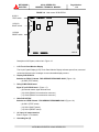
WARNING
Page Number:
1-2
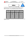
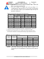
2
This UPS does not include an AC input circuit breaker (MCCB) to protect the
bypass and main input circuit.
supplied and installed.
The AC input circuit breaker (MCCB) is to be field
Circuit breaker (MCCB) specifications are as follows:
Capacity
(kVA)
AC input
Voltage (Vac)
AC input
Rating (Aac)
Recommended
Breaker (A)
7.5
208
23
30
10
208
30
35
15
208
45
60
20
208
61
75
30
208
91
125
40
208
121
150
50
208
151
200
AC output and DC input overcurrent protection and disconnection devices shall be field
supplied and installed.
MITSUBISHI ELECTRIC 2033C SERIES UPS
MITSUBISHI
ELECTRIC
2033C SERIES UPS
OWNERS / TECHNICAL MANUAL
Page Number:
1-3
1.1 GENERAL
The Mitsubishi 2033C Series UPS is designed to provide continuous and clean electrical power to
a critical load. In the event of an input power failure, the UPS will supply power to the critical load
for the specified battery time.
If the input power is not restored promptly, backup power from the UPS battery permits the orderly
shutdown of equipment supported by the UPS. The UPS is simple to start up, operate and
maintain.
The 2033C Series UPS is available in seven (7) kVA sizes: 7.5, 10, 15, 20, 30, 40 and 50kVA.
Specifications for each kVA model appear in Section 1.4. Models up to 30kVA have batteries
included in the UPS module cabinet. 40kVA and 50kVA models have external batteries. The
principles of operation described herein are applicable to all models.
This manual provides an overview of the 2033C Series components and their functions. The
appearance and purpose of operator controls and indicators is described with procedures for
operation, start-up, shutdowjn and basic maintenance included.
MITSUBISHI ELECTRIC 2033C SERIES UPS
MITSUBISHI
ELECTRIC
2033C SERIES UPS
OWNERS / TECHNICAL MANUAL
Page Number:
1-4
1.2 Definitions
UNINTERRUPTIBLE POWER SUPPLY SYSTEM (UPS) - All components within the UPS
Module Cabinet and associated batteries which function as a system to provide continuous,
conditioned AC power to a load. This is sometimes referred to as the "System".
UPS MODULE CABINET - The metal enclosure which contains the Converter / Charger,
Inverter, Static Transfer Switch, Internal Bypass line, operator controls, batteries (up to 30kVA
models only) and internal control systems required to provide specified AC power to a load.
UPS MODULE - The Converter / Charger and Inverter assemblies which, under the direction of
the internal control system and operator controls, provide specified AC power to a load.
CONVERTER / CHARGER - The UPS components which contain the equipment and controls
necessary to convert input AC power to regulated DC power required for battery charging and
for supplying power to the Inverter.
INVERTER - The UPS components which contain the equipment and controls necessary to
convert DC power from the Converter / Charger, or the battery, to AC power required by the
critical load.
STATIC TRANSFER SWITCH - The device which connects the critical load to the bypass line
when the Inverter cannot supply continuous power.
BYPASS LINE - The line which conducts electricity directly from the input power source to the
critical load during Maintenance or whenever the UPS is not completely operational.
AC INPUT POWER - Power provided by the electrical utility company, or auxiliary generator,
which is connected to the UPS for supplying the critical load and recharging the battery.
BATTERY - The rechargeable battery strings which supply DC power to the inverter to
maintain continuous AC power to the load during AC input power failure conditions.
MITSUBISHI ELECTRIC 2033C SERIES UPS
MITSUBISHI
ELECTRIC
Page Number:
1-5
2033C SERIES UPS
OWNERS / TECHNICAL MANUAL
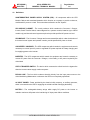
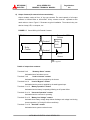
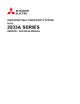
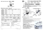
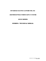
1.3 Overview
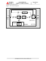
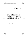
The UPS provides two power paths between the utility source and the critical load. Figure 1.1
shows the path for normal operation, with the load powered from the inverter. Figure 1.2 shows
the path for bypass operation, with the load supplied through the static bypass line.
FIGURE 1.1 Single Line Diagram - Normal Operation. Load powered by inverter.
Maintenance
Bypass
Switch
Static Transfer
Switch
CB3
CONVERTER
CB
INVERTER
AC input
Output
User
supplied
CB1
FI
FO
FB
52C 52CS(7.5-20kVA)
52MB&52L(30-50kVA)
CB2
Power Flow
Not in Use
BATTERY
40kVA, 50kVA:
External Battery
UPS Module
During normal operation, the path through the inverter is used to power the load.
Referring to Figure 1.1: Input AC power is converted to DC by the Converter. DC power is utilized to
charge the UPS battery and to provide power to the Inverter. The Inverter converts the DC power to
clean AC power to supply the critical load.
The conversion - inversion process eliminates any voltage transients or fluctuations existing in the
input power before it reaches the critical load.
* The Input circuit breaker(MCCB) for protection of the UPS and cables are field supplied and field
installed. (See WARNING 2 in section 1.0).
MITSUBISHI ELECTRIC 2033C SERIES UPS
MITSUBISHI
ELECTRIC
Page Number:
1-6
2033C SERIES UPS
OWNERS / TECHNICAL MANUAL
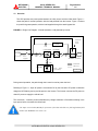
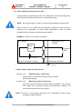
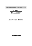
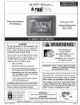
FIGURE 1.2 Single Line Diagram - Bypass Operation. Load fed through static bypass line.
Maintenance
Bypass
Switch
Static Transfer
Switch
CB3
CONVERTER
CB
INVERTER
AC input
Output
User
supplied
CB1
FO
FI
52C
52CS(7.5-20kVA)
52MB&52L(30-50kVA)
FB
CB2
Power Flow
Not in Use
BATTERY
40kVA, 50kVA:
External Battery
UPS Module
Referring to Figure 1.2, the Internal Static Bypass line is a Hard wired line through CB3 which
supplies the critical load with unconditioned input power. The purpose of this line is to route power
to the critical load while the UPS module is de-energized (converter and inverter), and during
Start-up before the system is fully operational.
The internal control system determines the operation of the two paths, with the load powered from
the inverter being the normal operation.
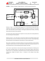
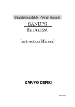
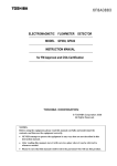
Referring to Figure 1.3, if the input power is interrupted, the battery will immediately supply the DC
power required by the Inverter to maintain continuous AC power to the load. A fully charged battery
will provide power for the specified time at the rated load, or longer at reduced load.
When power is restored after a low battery shutdown, the Converter automatically restarts operation,
recharges the batteries and the Inverter is automatically restarted without operator intervention. The
load is assumed by the inverter automatically without operator intervention.
In the event of a power failure, the Converter will de-energize and the batteries will discharge into
the Inverter and maintain power to the critical load until a) the battery capacity expires and the
inverter turns off, or b) input power is restored after which the converter will power the inverter and
simultaneously recharge the batteries. Figure 1.3 illustrates the flow diagram during battery
operation.
MITSUBISHI ELECTRIC 2033C SERIES UPS
MITSUBISHI
ELECTRIC
Page Number:
1-7
2033C SERIES UPS
OWNERS / TECHNICAL MANUAL
FIGURE 1.3 Single Line Diagram - Battery Operation
Maintenance
Bypass
Switch
Static Transfer
Switch
CB3
CONVERTER
CB
INVERTER
AC input
Output
User
supplied
CB1
FO
FI
52C
52CS(7.5-20kVA)
52MB&52L(30-50kVA)
FB
CB2
Power Flow
Not in Use
BATTERY
40kVA, 50kVA:
External Battery
UPS Module
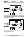
The UPS is equipped with an internal rotary type Maintenance Bypass Switch (MBS) that can be
used to divert utility power to the load during maintenance sessions. Figure 1.4 illustrates the power
path when the MBS is in the BYPASS mode.
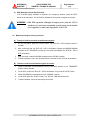
FIGURE 1.4 Single Line Diagram - UPS on Maintenance Bypass Operation.
Maintenance
Bypass
Switch
Static Transfer
Switch
CB3
CONVERTER
CB
INVERTER
AC input
Output
User
supplied
CB1
FI
FO
FB
52C
52CS(7.5-20kVA)
52MB&52L(30-50kVA)
CB2
Power Flow
Not in Use
BATTERY
40kVA, 50kVA:
External Battery
UPS Module
(7.5/10/15/20kVA)
The rotary maintenance bypass switch is shown as 52CS in Figure 1.4. 52CS is a two position
three point make-before-break transfer switch.
(30/40/50kVA)
Two contactors (52MB, 52L) are used instead of the 52CS.
A rotary switch(SWM) is used for
control of the two contactors.
MITSUBISHI ELECTRIC 2033C SERIES UPS
MITSUBISHI
ELECTRIC
2033C SERIES UPS
OWNERS / TECHNICAL MANUAL
Page Number:
1-8
The two positions are identified as NORMAL and BYPASS. In the NORMAL position the load is fed
by the UPS - either through the inverter or through the static bypass line. In the BYPASS position
the load is powered by an external source such as the utility or a generator. This transfer operation
must be made while the UPS is in the static bypass mode.
The transfer procedure to place the UPS in maintenance bypass mode, or from bypass mode to
normal operation mode is outlined below:
A) Transfer of load from inverter to maintenance bypass
1.
On the front panel, press the "STOP" button. The “BYP.OP.” LED illuminates within 3
seconds.
2.
After confirming that the “BYP.OP.” LED is illuminated, Rotate MBS(52CS/SWM) clockwise
to the “TRANSFER” position (Do not rotate 52CS/SWM if the “BYP.OP.” LED is NOT
illuminated).
3.
After 3 seconds, rotate 52CS/SWM clockwise to the “BYPASS” position.
4.
Transfer complete. Load is now powered from the external source. UPS can be shutdown.
B) Transfer of load from maintenance bypass to inverter
1.
Rotate 52CS/SWM counterclockwise from the “BYPASS” position to the “TRANSFER”
position, wait 5 seconds.
2.
On the UPS, confirm the “BYP.OP.” LED is illuminated. If not, press the “STOP” button.
3.
Rotate 52CS/SWM counterclockwise to the “NORMAL” position.
4.
On the UPS, press the “START” button. The “INV.OP.” LED should illuminate.
5.
Transfer complete. Load now powered by the inverter.
MITSUBISHI ELECTRIC 2033C SERIES UPS
MITSUBISHI
ELECTRIC
Page Number:
1-9
2033C SERIES UPS
OWNERS / TECHNICAL MANUAL
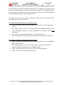
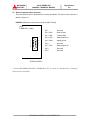
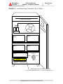
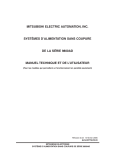
FIGURE 1.5a UPS Parts Location(7.5-20kVA)
UPS module
FRONT VIEW
4.Main PCB
UPFR-K
Converter &
Inverter Unit
1.LCD touch panel
monitor display
Cooling fan
3.Relay PCB
RYDR-X
2.Display PCB
DPAU-72
Battery
7.Maintenance bypass
transfer switch
52CS
5.AC input, AC
output terminal
6.Grounding bar
MITSUBISHI ELECTRIC 2033C SERIES UPS
MITSUBISHI
ELECTRIC
Page Number:
1-10
2033C SERIES UPS
OWNERS / TECHNICAL MANUAL
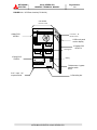
FIGURE 1.5b UPS Parts Location(30kVA)
UPS module
FRONT VIEW
4.Main PCB
UPFR-K
Converter &
Inverter Unit
1.LCD touch panel
monitor display
Cooling fan
7.Maintenance bypass
transfer switch
SWM
2.Display PCB
DPAU-72
Battery
3.Relay PCB
RYDR-X
5.AC input, AC
output terminal
6.Grounding
bar
MITSUBISHI ELECTRIC 2033C SERIES UPS
MITSUBISHI
ELECTRIC
Page Number:
1-11
2033C SERIES UPS
OWNERS / TECHNICAL MANUAL
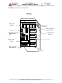
FIGURE 1.5c UPS Parts Location(40,50kVA)
4.Main PCB
UPFR-K
Converter &
Inverter Unit
1.LCD touch pane
monitor display
Cooling fan
2.Display PCB
DPAU-72
3.Relay PCB
RYDR-X
7.Maintenance bypass
transfer switch SWM
5.AC input, AC output
terminal
UPS module
FRONT VIEW
6.Grounding bar
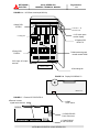
FIGURE 1.6 Display PCB DPAU-72
DPAU-57
DPAU-72
FIGURE 1.7 External I/F PCB RYDR-X
9.External contact
signal terminal block
8.SW5
TEST switch
RYDR-X
10.CN62 RS232C
D-sub Connector
11.CN64 RS232C
D-sub Connector
MITSUBISHI ELECTRIC 2033C SERIES UPS
2033C SERIES UPS
OWNERS / TECHNICAL MANUAL
MITSUBISHI
ELECTRIC
Page Number:
1-12
FIGURE 1.8 Main control PCB UPFR-K
8.SW11
TEST switch
12.SW13
BOOT switch
13.SW14
RESET switch
UPFR-K
Description of UPS parts, referred to in Figure 1.5:
1.
LCD Touch Panel Monitor Display
The Liquid Crystal Display (LCD) Touch Panel Monitor Display indicates power flow, measured
values and fault and error messages via user selectable display screens.
2.
Display PCB DPAU-72
Switches on DPAU-72 board : FOR SERVICE PERSONNEL ONLY (Figure 1.6):
- (8) SW5 (TEST switch)
3.
Relay PCB RYDR-X board
Signal I/F on RYDR-X board : (Figure 1.7):
- (9) External contact signal terminal block
- (10) CN62 (RS232C communication connector)
- (11) CN64 (RS232C communication connector)
4.
Main PCB UPFR-K
Switches on UPFR-K board : FOR SERVICE PERSONNEL ONLY (Figure 1.8):
- (8) SW11 (TEST switch)
- (12) SW13 (BOOT switch).
- (13) SW14 (RESET switch)
5.
AC input, AC output terminal
Refer to Figure 3.3 for details
6.
Grounding bar (E)
MITSUBISHI ELECTRIC 2033C SERIES UPS
MITSUBISHI
ELECTRIC
7.
2033C SERIES UPS
OWNERS / TECHNICAL MANUAL
Page Number:
1-13
Maintenance Bypass Switch (52CS/SWM) (FOR SERVICE PERSONNEL ONLY) This switch
is used to transfer the load from inverter power to external power for maintenance purposes.
Do not operate it under normal operation.
8.
"Test mode" switch (FOR SERVICE PERSONNEL ONLY)
This switch changes system operation to the test-mode. This switch is mounted on Display
PCB and Main PCB. (This switch should not be operated by personnel other than an
Authorized Service Engineer).
9.
External contact signal terminal block
Terminal block to connect contact signal input/output lines to and from external dry contacts.
Refer to FIGURE 2.3 for details.
10. RS232C connector (CN62)
Refer to Figure 2.6 for detail.
11. RS232C connector (CN64)
12. "BOOT" switch (FOR SERVICE PERSONNEL ONLY)
This switch boots the processor on the main control circuit board following alarm conditions.
(Do not operate this switch while inverter and converter are in operation).
13. "Reset" switch (FOR SERVICE PERSONNEL ONLY)
This switch resets errors resulting from alarm conditions. (Do not operate this switch while
inverter and converter are in operation).
MITSUBISHI ELECTRIC 2033C SERIES UPS
MITSUBISHI
ELECTRIC
Page Number:
1-14
2033C SERIES UPS
OWNERS / TECHNICAL MANUAL
1.4 Specifications
The UPS name plate displays the rated kVA as well as nominal voltages and currents. The
name plate is located on the interior side of the UPS front door.
TABLE 1.1 Power Specifications
Rated output
Input voltage
Output voltage
Power
3 phase / 4 wire
3 phase / 3 or 4 wire
7.5kVA/6kW
208
208
10kVA/8kW
208
208
15kVA/12kW
208
208
20kVA/16kW
208
208
30kVA/24kW
208
208
40kVA/32kW
208
208
50kVA/40kW
208
208
TABLE 1.2 UPS Module Information
HEAT LOSS
UPS
CABLE
WIDTH
DEPTH
HEIGHT
WEIGHT
(kVA)
ENTRY
(in/mm)
(in/mm)
(in/mm)
(lb./kg)
7.5
BOTTOM
17.7 / 450
31.5 / 800
43.3 / 1100
562 / 255*
3.2
10
BOTTOM
17.7 / 450
31.5 / 800
43.3 / 1100
562 / 255*
3.9
15
BOTTOM
17.7 / 450
31.5 / 800
43.3 / 1100
816 / 370*
5.1
20
BOTTOM
17.7 / 450
31.5 / 800
43.3 / 1100
816 / 370*
6.5
30
BOTTOM
23.6 / 600
31.5 / 800
59.0 / 1500
1235 / 560*
8.8
40
BOTTOM
27.6 / 700
31.5 / 800
59.0 / 1500
1082 / 490
11.9
50
BOTTOM
27.6 / 700
31.5 / 800
59.0 / 1500
1082 / 490
14.6
*:7.5-30kVA Including batteries
MITSUBISHI ELECTRIC 2033C SERIES UPS
@ 208V
(kBTU/h)
MITSUBISHI
ELECTRIC
Page Number:
1-15
2033C SERIES UPS
OWNERS / TECHNICAL MANUAL
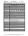
TABLE 1.3 Detail of Specifications
Rated Output kVA
7.5
10
15
20
30
40
50
Rated Output kW
6
8
12
16
24
32
40
AC INPUT CHARACTERISTICS
Configuration
3 phase, 4 wire
Voltage
120/208 V
Frequency
60 Hz +/- 5%
Reflected Current THD
4% typ. at 100% load; 7% typ. at 50% load
+15% ~ -25%
BATTERY
Type
VRLA
Ride Through
(at 100% load)
8min.
Nominal Voltage
360 Vdc
Minimum Voltage
300 Vdc
Number of Cells
180
5min.
11min.
7min.
5min.
AC OUTPUT
Configuration
3 phase, 3 or 4 wire
Voltage
120/208 V
Voltage Stability
+/-1%
Frequency
60 Hz
Frequency Stability
+/-0.01% in free running mode
Power Factor
0.8 nominal
Power Factor range
0.8 ~ 1.0 lagging (within output kW rating)
Voltage THD
2% typical THD at 100% Linear Load
4% typical THD at 100% non-linear load
Transient Response
+/-3% typical at 100% load step
+/-1% typical at loss/return of AC power
+/-3% typical at load transfer to/from static bypass
Transient Recovery
16.7 ms
Voltage Unbalance
2% typical at 100% unbalanced load
Phase Displacement
1deg. typical at 100% load
Inverter Overload
150% for 1 minute
System Overload
150% for 1 minute, 1000% for 1 cycle (with bypass available)
Bypass Overload
150% for 1 minute, 1000% for 1 cycle
Crest Factor Capabilities
3:1
ENVIRONMENTAL
Cooling
Forced Air
Operating Temperature
32゚F ~ 104゚F (0゚C ~ 40゚C).
Recommended 59゚F ~ 77゚F (15゚C ~ 25゚C)
Relative Humidity
5% ~ 95% Non Condensing
Altitude
0 ~ 5000 feet No De-rating
Location
Temperature-controlled, indoor area free of conductive contaminants
MITSUBISHI ELECTRIC 2033C SERIES UPS
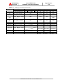
TABLE 1.4
Component
Page Number:
1-16
2033C SERIES UPS
OWNERS / TECHNICAL MANUAL
MITSUBISHI
ELECTRIC
Rating of Contactors and Fuses
Description
UPS Rating (kVA)
Component Rating @ 208V,3 phase, 60 Hz
7.5
10
15
20
30
40
50
CB1
AC Input Contactor
60A
100A
150A
150A
CB2
DC Input Contactor
60A
100A
150A
150A
Static Bypass Input
60A
100A
150A
60A
100A
150A
150A
AC Input Fuse
140A/660V
180A/600V
280A/660V
280A/660V
Battery Input Fuse
140A/660V
180A/600V
280A/660V
280A/660V
AC Output Fuse
140A/660V
180A/600V
280A/660V
280A/660V
200A/660V
280A/660V
280A/660V
6.3A/250V
6.3A/250V
6.3A/250V
CB3
52C
FIU-W
FBP,FBN
FOU-W
(OPTION)
FSU-W
F1,F2,F3
F1
Contactor
AC Output Contactor
Static Bypass Input
Fuse
UPER-Y/UPFR-K
6.3A/250V
CABR-JA
12A/600V
MITSUBISHI ELECTRIC 2033C SERIES UPS
150A
Page Number:
2-1
2033C SERIES UPS
OWNERS / TECHNICAL MANUAL
MITSUBISHI
ELECTRIC
2.0 OPERATOR CONTROLS AND INDICATORS
The 2033C Series operator controls and indicators are located as follows:
Maintenance bypass switch and contactors
: Inside the module
UPS status indicators
: Door exterior
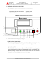
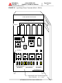
FIGURE 2.1 Operation/Display Panel (Front panel)
MITSUBISHI
1
4
2
EPO
INV OP. BYP OP.
START
STOP
MBP
SILENCE CLEAR
BAT OP. FAILURE
3
2033C SERIES UPS
5
6
7
8
9
10
2.1 LCD Touch Panel Monitor Display and Keypad
1) LCD Touch Panel Monitor Display
The Liquid Crystal Display (LCD) Touch panel Monitor Display indicates power flow,
measured values and fault and error messages via user selectable display screens.
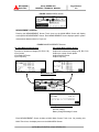
MAIN MENU SCREEN
The MAIN MENU Screen is shown in Figure 2.2. The MAIN MENU screen displays the
system Mimic diagram, and includes four MEASUREMENT Screen Touch icons: AC Input,
Bypass Input, Battery, AC Output and one FAULT DISPLAY Screen Touch Icon: Fault/Alarm
History. Date and Time are displayed at the bottom of the display.
MITSUBISHI ELECTRIC 2033C SERIES UPS
MITSUBISHI
ELECTRIC
2033C SERIES UPS
OWNERS / TECHNICAL MANUAL
Page Number:
2-2
FIGURE 2.2 MAIN MENU Screen
MEASUREMENT SCREENS
Pressing the MEASUREMENT Screen Touch icons on the MAIN MENU Screen will display
each specific MEASUREMENT Screen. Each MEASUREMENT Screen displays specific system
measurement data as shown in Figure 2.3.
FIGURE 2.3 MEASUREMENT Screens
AC Input Measurement Screen
AC Output Measurement Screen
Input line to neutral rms voltage (A-N, B-N, C-N)
Input Current
Input Real KW Power
Input Frequency
Output line to neutral rms voltage (A-N, B-N, C-N)
Output rms current of each phase
Output Real KW Power
Output Frequency
MAIN MENU Screen
Battery Measurement Screen
DC Bus Voltage
Battery Charge/Discharge Current
Each MEASUREMENT Screen includes a MAIN Menu Screen Touch Icon. On pressing this
MAIN Touch icon, the display returns to the MAIN MENU Screen.
MITSUBISHI ELECTRIC 2033C SERIES UPS
2033C SERIES UPS
OWNERS / TECHNICAL MANUAL
MITSUBISHI
ELECTRIC
Page Number:
2-3
FAULT DISPLAY SCREEN
Pressing the FAULT DISPLAY Screen Touch icon on the MAIN MENU Screen will display the
Fault display screen. Fault/Alarm data including fault codes and occurrence/restore dates as
well as fault/alarm History can be displayed as shown in Figure 2.4. The FAULT DISPLAY
Touch icon will flash on the MAIN MENU Screen if there are Fault/Alarms that have not been
restored. Pressing the DETAIL DISPLAY Touch icon will display faults in more detail. Pressing
the Rest. Item Delete Touch icon will delete all fault/alarms that are selected by the Cursor
Touch icons and have been restored. On Pressing the Main Touch Icon, the display returns to
the MAIN MENU Screen.
FIGURE 2.4 FAULT DISPLAY Screen
MAIN MENU Screen
MITSUBISHI ELECTRIC 2033C SERIES UPS
Page Number:
2-4
2033C SERIES UPS
OWNERS / TECHNICAL MANUAL
MITSUBISHI
ELECTRIC
DATE & CLOCK SETUP SCREEN
Pressing the lower right of the MAIN MENU Screen will display the date & clock setup screen.
On Pressing the END Touch Icon, the display returns to the MAIN MENU Screen.
FIGURE 2.5 DATE & CLOCK SETUP Screens
終了
【現在時刻】
END
【SET CLOCK】
2000年 1 /1 /1月 2000 1日 12時 00分 00秒
12 : 00 : 00
5
6
7
8
9
0
1
2
3
4
-
▲
CLR
▼
ENT
Pressing the each point can
set the date or clock.
NOTE: The display measurement values shown for LCD Monitor Displays are samples only.
2) Load on inverter [INV OP.] (green)
Illuminated when power is supplied from inverter to the critical load.
3) Battery operation [BAT OP.] (yellow)
Illuminated when the battery is operating following an AC power failure.
4) Load on bypass [BYP OP.] (yellow)
Illuminated when power is supplied to load devices by static bypass.
5) UPS failure [FAILURE] (red)
Illuminated when UPS is in fault mode.
6) Inverter start [START] (green)
Inverter start button.
When pressed, the load will transfer from the static bypass line to the inverter.
7) Inverter stop [STOP] (gray)
Inverter stop button. When pressed, the inverter can be stopped.
The load will transfer from the inverter to the static bypass line.
8) Alarm Silence [SILENCE] (gray)
Audible alarm is silenced when this button is pressed.
9) Clear [CLEAR] (gray)
Clears errors in UPS system.
10)Emergency Power Off [EPO] (red)
Shuts down UPS when pressed. Load is dropped.
11)Load on maintenance bypass [MBP] (red)
Illuminated when power is supplied to load devices by maintenance bypass.
MITSUBISHI ELECTRIC 2033C SERIES UPS
MITSUBISHI
ELECTRIC
Page Number:
2-5
2033C SERIES UPS
OWNERS / TECHNICAL MANUAL
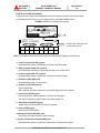
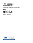
2.2 External Signal Terminal Block
The UPS is equipped with a series of input/output terminals for the external annunciation of
alarms and the remote access of certain UPS functions. Layout of terminals is shown in Figure
2.6, with a functional description of the input/output port presented:
FIGURE 2.6 External Signal Terminal Block (NEC Class2)
TB
1
2
3
4
5
6
7
8
9
10
11
12
13
14
15
16
17
18
EMERGENCY STOP (Optional)
(User supplied dry contact)
BATTERY TEMP. HIGH (Optional)
- For external battery cabinet.
SUMMARY ALARM
LOAD ON INVERTER
LOAD ON BYPASS
BATTERY OPERATION
CONVERTER OPERATION
BATTERY LOW VOLTAGE
OVERLOAD
UPS
MITSUBISHI ELECTRIC 2033C SERIES UPS
(User supplied sensor
and dry contact)
Page Number:
2-6
2033C SERIES UPS
OWNERS / TECHNICAL MANUAL
MITSUBISHI
ELECTRIC
A) Output Contacts (for external alarm annunciation)
Output contacts consist of form “A” dry type contacts. The rated capacity of all output
contacts is 120Vac/0.5Aac or 30Vdc/1Adc. All dry contacts must be operated at their
rated values or lower. Figure 2.7 illustrates a typical installation. The external relay can
also be a lamp, LED, or computer, etc.
FIGURE 2.7 Control Wiring for External Contacts
UPS Cabinet
External to UPS
Cabinet
Terminal
Relay
Coil
Relay
Contact
Terminal
Power
Source
User supplied
Details of output alarm contacts :
Terminals 5 to 6
“Summary Alarm” contact
Activated when a fault alarm occurs.
Terminals 7 to 8
“Load on Inverter” contact
Activated when the power is supplied by the inverter.
Terminals 9 to 10
“Load on Bypass” contact
Activated when the power is supplied by the static bypass input.
Terminals 11 to 12 “Battery Operation” contact
Activated when the battery is operating following an AC power failure.
Terminals 13 to 14 “Converter Operation” contact
Activated when the converter is operating.
Terminals 15 to 16 “Battery Low Voltage” contact
Activated when battery voltage drops below discharge end voltage level during
inverter operation (i.e. During AC failure conditions).
Terminals 17 to 18 “Overload” contact
Activated when a system overload occurs.
MITSUBISHI ELECTRIC 2033C SERIES UPS
MITSUBISHI
ELECTRIC
Page Number:
2-7
2033C SERIES UPS
OWNERS / TECHNICAL MANUAL
B) Input Contacts (for remote access of UPS)
External contacts are provided by the user of the UPS system. The terminal voltage at the
UPS is 24Vdc. External dry contacts are to be provided accordingly.
NOTE:
Do not apply voltages to remote access input terminals. Damage to UPS may result.
Refer to Figure 2.8 for a typical wiring configuration. Although this figure shows the
emergency stop configuration, the same wiring arrangement is used for battery
temperature high. See below for terminal connection details.
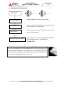
FIGURE 2.8 Remote "Stop" Contact Connections
UPS Cabinet
External to UPS
Cabinet
Relay
1
Emergency
Stop
Coil
2
24 VDC
Relay Coil current : 8.3mA
Use Momentary Switches
User supplied
Details of input contacts for remote access :
Terminals 1 to 2
“Emergency Stop” contact input
Used to perform a remote UPS emergency power off (EPO).
The load will be dropped.
Terminals 3 to 4
“Battery Temp. High” contact input
Input fed by a thermocouple that monitors battery temperature. The converter
float voltage level is reduced for battery over-temperature conditions. The
external thermocouple will be user supplied
NOTE : In all cases, a switch having a protective cover is recommended in order to reduce
possibility of accidental operation.
MITSUBISHI ELECTRIC 2033C SERIES UPS
Page Number:
2-8
2033C SERIES UPS
OWNERS / TECHNICAL MANUAL
MITSUBISHI
ELECTRIC
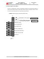
2.3 External communication connector
This is an RS232C port for “DiamondLink”* monitoring software. The layout of the connector is
shown in Figure 2.9.
FIGURE 2.9 External communication connector (NEC Class2)
CN62
D-SUB 9Pin
(male)
1
2
3
4
5
6
7
8
9
Pin 1.
: Not used
Pin 2. RXD
: Receive data
Pin 3. TXD
: Transmit data
Pin 4. DTR
: Always high level
Pin 5. GND
: Signal ground
Pin 6.
: Not used
Pin 7. RTS
: Always high level
Pin 8.
: Not used
Pin 9.
: Not used
RYDR-O/ RYDR-X
* Consult MITSUBISHI ELECTRIC AUTOMATION, INC. for detail on “Diamond Link” monitoring
software and its capabilities.
MITSUBISHI ELECTRIC 2033C SERIES UPS
MITSUBISHI
ELECTRIC
Page Number:
3-1
2033C SERIES UPS
OWNERS / TECHNICAL MANUAL
3.0 INSTALLATION AND OPERATION
3.1 Transportation and Installation
TABLE 3.1 How to transport and install the system
Transportation
Installation
Transport unit with forklift.
Pull out the UPS cabinet as shown in Figure 3.1
Fix the UPS unit in place using the four (4) leveling feet.
Note : Do not transport in a horizontal position. Cabinets should be maintained upright within +/15° of the vertical during handling.
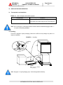
3.2 Handling
The UPS is shipped in export packaging. Remove the UPS from the package only when it is
ready for installation.
FIGURE 3.1 Handling
Leveling
feet
2
1
5
4
3
RAMP
Roof of the package
during shipping
Note : The figure 3.1 export packaging is for 7.5kVA through 20kVA UPS only.
MITSUBISHI ELECTRIC 2033C SERIES UPS
Page Number:
3-2
2033C SERIES UPS
OWNERS / TECHNICAL MANUAL
MITSUBISHI
ELECTRIC
3.3 Installation Procedure
A) Note the load tolerance of the floor
Refer to Table 3.2 for list of UPS weights:
TABLE 3.2 List of UPS weights
UPS Capacity (kVA)
7.5
10
15
20
30
40
50
Weight (lb.)
562
562
816
816
1235
1082
1082
Note: 40kVA and 50kVA UPS have batteries external to module cabinet
Please refer to the remote battery supply installation manual.
B) Minimum clearance required for ventilation
Right side
1.0" (25 mm) (not required when sidecars are used)
Left side
1.0" (25 mm) (not required when sidecars are used)
Back side
7.8" (200 mm)
Top side
39.4" (1000 mm)
C) Space requirement for routine maintenance
Allow for the following space at the time of installation.
Front
39.4" (1000 mm)
Sides
1.0" (25 mm)
Rear
7.8" (200 mm)
D) Battery
Please refer to the following when installing and maintaining batteries:
1.
Servicing of batteries should be performed or supervised by personnel
knowledgeable of batteries and the required precautions. Keep unauthorized
personnel away from batteries.
2.
When installing or replacing batteries, install or replace with the same number
and type per Table 3.3
TABLE 3.3 Type and number of battery
Type
Manufacturer
7.5kVA,10kVA
PM12-7.2
NP7-12
Power Battery Inc.
Yuasa Corp.
30
15kVA,20kVA
PM12-18
NP18-12B
Power Battery Inc.
Yuasa Corp.
30
30kVA
PM12-18
NP18-12B
NP18-12BFR
Power Battery Inc.
Yuasa Corp.
Yuasa Corp.
30
40kVA,50kVA
MITSUBISHI ELECTRIC 2033C SERIES UPS
Number
2033C SERIES UPS
OWNERS / TECHNICAL MANUAL
MITSUBISHI
ELECTRIC
Page Number:
3-3
Note: 40kVA and 50kVA UPS batteries are external to module cabinet.
Please refer to the remote battery supply installation manual.
3.
CAUTION - Do not dispose of battery or batteries in a fire. The battery may
explode.
4.
CAUTION - Do not open or mutilate the battery or batteries. Released electrolyte
is harmful to the skin and eyes and may be toxic.
5.
CAUTION - A battery can present a risk of electrical shock and high short circuit
current. The following precautions should be observed when working on batteries:
-
Remove watches, rings, or other metal objects.
-
Use tools with insulated handles.
-
Wear rubber gloves and boots.
-
Do not lay tools or metal parts on top of batteries.
-
Disconnect charging source prior to connecting or disconnecting battery
terminals.
3.4 Procedure for Cable Connections (Refer to Table 3.4 for cable sizes.)
I.
Confirm the capacity of the UPS being installed. Identify the input/output power terminal
blocks as shown in the appropriate Figure 3.2 or Figure 3.3-Figure 3.5.
II.
Connect the grounding conductor from the input service entrance to the UPS ground bar.
III.
Confirm that an external input circuit breaker sized to protect both the converter input and
the bypass lines is installed. Consult equipment nameplate for current ratings. Connect
the AC power source cables from the input service entrance to the UPS’ INPUT power
terminals identified as A, B, C and N in Figure 3.3-Figure 3.5. Input cables must be sized
for an ampere rating larger than the maximum current capacity of the UPS.
IV.
Refer to Table 3.4 for recommended cable sizes. Referring to Figure 3.3-Figure 3.5,
connect UPS’ OUTPUT load terminals A, B, C and N to load distribution panel.
V.
Connect external signal terminal block as needed. Refer to section 2.2 and Figure 2.3 for
functional description. 12 AWG, or less, shielded conductor is recommended.
MITSUBISHI ELECTRIC 2033C SERIES UPS
Page Number:
3-4
2033C SERIES UPS
OWNERS / TECHNICAL MANUAL
MITSUBISHI
ELECTRIC
NOTES: 1. Confirm that all UPS internal contactors (breakers) "CB1", "CB2", and
"CB3" are open before energizing UPS.
2. UPS power terminals are supplied with stud type fittings. It is
recommended that compression lugs be used to fasten all input/output
power cables. Refer to Table 3.5 for recommended compression lugs and
appropriate crimping tool
Table 3.4 Recommended Cable Size and Torque Requirements
UPS
Input Side * 1
Output Side * 1
Torque
Cable *2
Torque
Size
(in. lbs)
Size
(in. lbs)
7.5kVA (208V)
8 AWG or larger
180 in. lbs
8 AWG or larger
180 in. lbs
10kVA (208V)
8 AWG or larger
180 in. lbs
8 AWG or larger
180 in. lbs
15kVA (208V)
8 AWG or larger
180 in. lbs
8 AWG or larger
180 in. lbs
20kVA (208V)
6 AWG or larger
180 in. lbs
6 AWG or larger
180 in. lbs
30kVA (208V)
2 AWG or larger
180 in. lbs
2 AWG or larger
180 in. lbs
40kVA (208V)
2/0 AWG or larger
180 in. lbs
2/0 AWG or larger
180 in. lbs
50kVA (208V)
2/0 AWG or larger
180 in. lbs
2/0 AWG or larger
180 in. lbs
Capacity (kVA)
Cable *
2
*1 - Voltage drop across power cables not to exceed 3% of nominal source voltage.
*2 - Allowable ampere ratings based on 90゚C insulation at an ambient temperature of 30゚C.
No more than 3 conductors in a raceway without de-rating. Copper conductors assumed.
TABLE 3.5 Crimp Type Compression Lug
WIRE
WIRE
SIZE
STRAND
(CODE)
CLASS
VENDOR
CAT. NO.
COLOR KEY
DIE INDEX
8
B
BURNDY
YA8C-L2
RED
49
6
B
BURNDY
YA6C-L3
BLUE
7 / 374
4
B
BURNDY
YA4C-L3
GRAY
8 / 346
2
B
BURNDY
YA2C-L
BROWN
10
2/0
B
BURNDY
YA26-L3
BLACK
13
NOTE:
RECOMMENDATION
CRIMP TOOL REQUIRED
BURNDY TYPE Y35 OR Y46
When using crimp type lugs, the lugs should be crimped to the
specifications given in the manufacturer's instructions for both crimp tool
and lug.
MITSUBISHI ELECTRIC 2033C SERIES UPS
Page Number:
3-5
2033C SERIES UPS
OWNERS / TECHNICAL MANUAL
MITSUBISHI
ELECTRIC
Fig.3.2 UPS Terminal Designation
Static Transfer
Switch
CB3
CONVERTER
AC input
Terminals:
INPUT
A,B,C,N
INVERTER
Output
CB1
FI
FO
52C
52CS
CB2
52CS(7.5-20kVA)
52MB&52L(30-50kVA)
FB
BATTERY
40kVA, 50kVA:
External Battery
MITSUBISHI ELECTRIC 2033C SERIES UPS
UPS Module
Terminals:
OUTPUT
A,B,C,N
MITSUBISHI
ELECTRIC
2033C SERIES UPS
OWNERS / TECHNICAL MANUAL
Page Number:
3-6
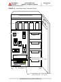
FIGURE 3.3 Input/Output Power Terminals (7.5kvA - 20kVA)
Control printed circuit boards
Inverter and Converter
Fan
Battery
Battery
Battery
Battery
RYDR-X
TRANSFER
BYPASS
NORMAL
A B C N A B C N
(INPUT) (OUTPUT)
52CS
Input/Output Power Terminal Designation
ALL POWER TERMINALS USE 1/4” (6 MM) DIAMETER BOLTS
MITSUBISHI ELECTRIC 2033C SERIES UPS
2033C SERIES UPS
OWNERS / TECHNICAL MANUAL
MITSUBISHI
ELECTRIC
Page Number:
3-7
FIGURE 3.4 Input/Output Power Terminals (30kVA)
Control printed circuit boards
Converter & Inverter Unit
Cooling fan
TRANSFER
NORMAL
BYPASS
Battery
MBS
Battery
N
P
(DC INPUT)
Battery
RYDR-X
DC Input Power Terminal
HOLE DIAMETER: 0.28” (7 MM)
Battery
A B C N A B C N
(INPUT)
(OUTPUT)
.
Grounding bar
AC Input/Output Power Terminal Designation
HOLE DIAMETER: 0.36” (9 MM)
MITSUBISHI ELECTRIC 2033C SERIES UPS
Page Number:
3-8
2033C SERIES UPS
OWNERS / TECHNICAL MANUAL
MITSUBISHI
ELECTRIC
FIGURE 3.5 Input/Output Power Terminals (40kvA - 50kVA)
Control printed circuit boards
Converter & Inverter Unit
Cooling fan
TRANSFER
BYPASS
NORMAL
RYDR-X
A
B
C
(AC INPUT)
MBS
N
A
B
C
(AC OUTPUT)
N
N
P
(DC INPUT)
Grounding bar
Input/Output Power Terminal Designation
HOLE DIAMETER: 0.47” (12 MM)
MITSUBISHI ELECTRIC 2033C SERIES UPS
2033C SERIES UPS
OWNERS / TECHNICAL MANUAL
MITSUBISHI
ELECTRIC
Page Number:
3-9
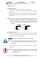
3.5 Operating Procedures
A) UPS Start-up Procedure
1.
Close External Input Circuit Breaker (User supplied. Refer to warning 2).
2.
The “BYP.OP.” illuminates and power is supplied to the critical load from the static bypass
line automatically.
3.
Within ten (10) seconds, the “INV.OP.” LED flashes and the Inverter starts. The UPS will
automatically transfer the load from the static bypass line to the inverter and the “INV.OP.”
light illuminates.
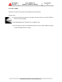
NOTE : If code “81” is indicated on the FAULT DISPLAY Screen, please check the
position of EPO button. If EPO button is in the ON position, press the
button to clear EPO as shown in figure 3.6. Press the “CLEAR” button. If
code “99” is indicated on the FAULT DISPLAY Screen, press “CLEAR”
button again.
FIGURE 3.6 EPO button
EPO “On” position
Normal position
B) UPS Shutdown Procedure
1.
If a total UPS module (inverter and converter) shutdown is required, press the "STOP"
button on the front panel. Within 3 seconds the “BYP.OP.” LED will illuminate and the
UPS will transfer the load to the static bypass line.
WARNING
: Verify the load is OFF if the next step is to be performed .
NOTE : Power to the critical load is supplied through the static bypass line.
Power to the critical load will be lost after execution of the next step. The
load will drop.
2.
If turning off all power to the critical load is desired, open the AC Input Circuit Breaker
(User supplied.).
CAUTION : In bypass mode, all UPS power terminals are still live. Lethal voltages
are present. De-energize all external sources of AC and DC power
before handling UPS.
MITSUBISHI ELECTRIC 2033C SERIES UPS
2033C SERIES UPS
OWNERS / TECHNICAL MANUAL
MITSUBISHI
ELECTRIC
Page Number:
3-10
C) EPO (Emergency Power Off) Procedure
If an all power supply shutdown is required in an emergency situation, press the "EPO"
button on the front panel. The UPS will be shutdown and no power is supplied to the load.
WARNING : With EPO operation, although all output power from the UPS is
shutdown, it is necessary to manually open the input circuit breaker
(user supplied), to remove the input power to the UPS.
3.6 Maintenance bypass set-up procedures
A) Transfer of load from inverter to maintenance bypass
1.
On the front panel, press the "STOP" button. The “BYP.OP.” LED illuminates within 3
seconds.
2.
After confirming that the “BYP.OP.” LED is illuminated, Rotate the MBS(52CS/SWM)
clockwise to the “TRANSFER” position (Do not rotate 52CS/SWM if the “BYP.OP.” LED is
NOT illuminated).
3.
After 3 seconds, rotate 52CS/SWM clockwise to the “BYPASS” position.
4.
Transfer complete. Load is now powered from the external source. UPS can be shutdown.
B) Transfer of load from maintenance bypass to inverter
1.
Rotate 52CS/SWM counterclockwise from the “BYPASS” position to the “TRANSFER”
position, wait 5 seconds.
2.
On the UPS, confirm the “BYP.OP.” LED is illuminated. If not, press the “STOP” button.
3.
Rotate 52CS/SWM counterclockwise to the “NORMAL” position.
4.
On the UPS, press the “START” button. The “INV.OP.” LED should illuminate.
5.
Transfer complete. Load now powered by the inverter.
MITSUBISHI ELECTRIC 2033C SERIES UPS
MITSUBISHI
ELECTRIC
4.0
2033C SERIES UPS
OWNERS / TECHNICAL MANUAL
Page Number:
4-1
RESPONSE TO UPS FAILURE
UPS FAULT
Depress “SILENCE” button on the front panel.
Annunciator Silence
Refer to the list of fault codes for a description of the
Recording of Fault
error. See section 6. For fault codes
Take necessary action per the list of fault codes in
Primary Action
section 6 of this manual.
Information to Service Center
When faults occur, contact the Authorized Mitsubishi
Service Representative or call Mitsubishi at
1-800-887-7830.
Note :
The error code indicated on the FAULT DISPLAY Screen of the LCD Display at the
time of UPS alarm condition is very important. In order to minimize repair time,
please include this information along with the operation status and load status, on all
correspondence with Mitsubishi’s field service group.
MITSUBISHI ELECTRIC 2033C SERIES UPS
2033C SERIES UPS
OWNERS / TECHNICAL MANUAL
MITSUBISHI
ELECTRIC
Page Number:
5-1
5.0 PARTS REPLACEMENT
Contact Mitsubishi or its Authorized Service Center on all issues regarding the replacement
of parts.
A)
Battery
Battery lifetime may vary according to the frequency of use and the average ambient
operating temperature. Battery end of life is defined as the state of charge resulting
in an ampere-hour capacity less than, or equal to, 80% of nominal capacity. Replace
battery if capacity is within this percentage.
B)
UPS Component Parts
Contact Mitsubishi or its Authorized Service Center for a complete parts replacement
schedule. Recommended replacement time interval varies with operating environment.
Contact Mitsubishi or its Authorized Service Center for specific application
recommendations.
MITSUBISHI ELECTRIC 2033C SERIES UPS
MITSUBISHI
ELECTRIC
2033C SERIES UPS
OWNERS / TECHNICAL MANUAL
Page Number:
6-1
6.0 FAULT CODES
This section covers the fault codes, their description and required action.
At time of error :
A) Verify and record the occurrence of the alarm. Note fault code on the FAULT DISPLAY
Screen of the LCD Display .
Contact Mitsubishi Electric Automation, Inc. at 1-800-887-7830.
B) If the External AC Input Circuit Breaker (MCCB) is in the trip state, depress the toggle
to reset the breaker before re-closing.
MITSUBISHI ELECTRIC 2033C SERIES UPS
20033C SERIES UPS
OWNERS / TECHNICAL MANUAL
MITSUBISHI
ELECTRIC
Page Number:
6-2
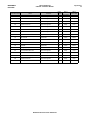
Failure Code List
Note 1
LCD Failure Code
Status
Guidance
Buzzer
Note 2
External sendout contact
Note 3
Failure LED
00
Test mode (Pulse check)
-
[1]
-
-
01
Maintenance mode
-
[1]
-
-
10
Battery circuit abnormal
[1]
Minor
Flicker
11
Battery test
-
-
-
12
Battery circuit abnormal
[1]
Minor
Flicker
13
Battery depleted warning
-
[1]
Alarm
Flicker
14
Battery depleted
-
[2]
Alarm
Lit up
15
Battery temperature abnormal
Check battery
[1]
Alarm
Flicker
16
Battery temperature abnormal
Check battery
[1]
Minor
Flicker
17
Battery charge voltage abnormal
Call service engineer
[1]
Alarm
Flicker
18
DC voltage abnormal
Call service engineer
[1]
Minor
Flicker
19
Battery depleted (Converter
overload)
Check AC input voltage
[2]
Major
Lit up
21
AC input voltage out of range
Check AC input voltage
[1]
Alarm
-
22
AC input phase rotation error
Check AC input voltage
[1]
Minor
Flicker
23
Converter overload
Call service engineer
[1]
Alarm
Flicker
24
Converter over current
Call service engineer
[1]
Minor
Flicker
25
Converter abnormal (DCOV)
Call service engineer
[2]
Major
Lit up
26
Converter abnormal (DCUV)
Call service engineer
[2]
Major
Lit up
27
Converter abnormal
Call service engineer
[2]
Major
Lit up
28
Converter abnormal at pre-charge
Call service engineer
[2]
Major
Lit up
31
Inverter voltage abnormal
Call service engineer
[1]
Minor
Flicker
32
Inverter abnormal (VLOV)
Call service engineer
[2]
Major
Lit up
33
Inverter abnormal (VLUV)
Call service engineer
[2]
Major
Lit up
34
Inverter abnormal (OC)
Call service engineer
[2]
Major
Lit up
35
Inverter abnormal
Call service engineer
[2]
Major
Lit up
36
52C abnormal
Call service engineer
[1]
Minor
Flicker
37
52C abnormal
Call service engineer
[1]
Minor
Flicker
41
Bypass voltage out of range
Check bypass input
-
Alarm
Flicker
Call service engineer
Call service engineer
MITSUBISHI ELECTRIC 2033C SERIES UPS
20033C SERIES UPS
OWNERS / TECHNICAL MANUAL
MITSUBISHI
ELECTRIC
Page Number:
6-3
Note 1
LCD Failure Code
Status
Guidance
Buzzer
Note 2
External sendout contact
Note 3
Failure LED
53
Transfer circuit abnormal
Call service engineer
[1]
Minor
Flicker
54
Control circuit error
Call service engineer
[2]
Major
Lit up
55
Control circuit error
Call service engineer
[2]
Major
Lit up
56
Control circuit error
Call service engineer
[2]
Major
Lit up
57
Control circuit error
Call service engineer
[2]
Major
Lit up
58
Control circuit error
Call service engineer
[1]
Minor
Flicker
59
Control circuit error
Call service engineer
[2]
Major
Lit up
71
Overload
Reduce load
[1]
Alarm
Flicker
72
kW overload
Reduce load
[1]
Alarm
Flicker
73
Instantaneous overload
Reduce load
[1]
Alarm
Flicker
74
Load abnormal
Check load
[1]
Alarm
Flicker
76
Overload
Reduce load
[1]
Alarm
Flicker
81
Emergency stop activated
[1]
Alarm
Flicker
82
Fin temperature abnormal
Call service engineer
[2]
Major
Lit up
96
Control circuit error
Call service engineer
[2]
Major
Lit up
97
Restart after battery depleted
-
Alarm
-
98
Control circuit error
Call service engineer
[2]
Major
Lit up
99
Start up
Press Clear button
-
Alarm
-
-
-
MITSUBISHI ELECTRIC 2033C SERIES UPS
2033C SERIES UPS
OWNERS / TECHNICAL MANUAL
MITSUBISHI
ELECTRIC
Page Number:
6-4
(Note 1)
Audible annunciator: [1] intermittent sound, [2] continuous sound.
(Note 2)
-
"Major" is defined as a major failure. Load transferred from inverter to the static
bypass line;
-
"Minor" is defined as a minor failure. UPS continues to operate normally, but cause of
alarm must be identified;
-
“Over" is defined as an overload condition. Load will transfer from inverter to the static
bypass line and may or may not return to the inverter. Return to inverter will occur only
if overload corrects itself and output load is within rating of UPS. (Note: Inverter may
need to be restarted manually subsequent to an output bolted fault.)
(Note 3)
Indicates one of two possible LED illumination patterns - continuously on (lit) or
intermittent (flicker).
MITSUBISHI ELECTRIC 2033C SERIES UPS
MITSUBISHI
ELECTRIC
2033C SERIES UPS
OWNERS / TECHNICAL MANUAL
Page Number:
7-1
7.0 Warranty & Out of warranty Service
The Mitsubishi Electric UPS Systems Group Service Department has many Authorized Service Centers place
strategically throughout the US, Canada and Latin America. For both in warranty and out of warranty service,
please contact Mitsubishi Electric Automation, Inc. at (847) 478-2500. To register your UPS for warranty
purposes, please complete the warranty registration form and fax it to the Mitsubishi Electric UPS Systems
Group, Service Department fax line shown on the registration form. (Next page)
For warranty purposes, it is essential that any and all service work that may be required on your Mitsubishi
brand UPS equipment is performed by a Mitsubishi Electric Authorized Service Center. The use of nonauthorized service providers may void your warranty.
Mitsubishi Electric Automation Inc,
UPS Systems Group Service Department
500 Corporate Woods Parkway,
Vernon Hills, Illinois 60061, USA
Phone: (847) 478-2500
Fax: (847) 478-2290
MITSUBISHI ELECTRIC 2033C SERIES UPS
Page Number:
7-2
2033C SERIES UPS
OWNERS / TECHNICAL MANUAL
MITSUBISHI
ELECTRIC
Mitsubishi Electric Automation, Inc.
UNINTERRUPTIBLE POWER SUPPLIES
500 Corporate Woods Parkway, Vernon Hills, IL 60061
Phone: (847) 478-2643, Fax: (847) 478-2290
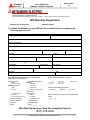
UPS Warranty Registration
__ Register UPS for Warranty
__ Address Change
To validate the Warranty on your UPS this form must be filled out completely by
Customer and returned.
CUSTOMER INFORMATION
Your Name:
Job Title:
Company Name:
Division / Department:
Address:
City:
State:
Zip Code:
Country:
Province:
Business Phone:
Ext:
Fax:
E-Mail:
Internet Address:
@
UPS Model #:
Capacity (kVA):
Start-Up Date:
UPS Serial #:
Authorized Mitsubishi Service Company (if known):
/
/
Signature:
Date:
/
Which ONE of These Best Describes Your Organization’s
Primary Business Classification?
{Energy Producer}
__ Utility
__ Alternate Energy
{Manufacturing Co.}
__ OEM
__ Education/Univ. Service
{Service}
__ Consulting
Number of Employees at This Location is:
__ 1 – 19
__ 20 – 49
__ 50 – 99
__ 100 - 249
__ 250 - 499
__ 500 - 999
__1000 or more
__ Engineering
__ Outsourcing
__ Process
__ Financial/Legal/Insurance
{Expectations}
__ Consumer Goods
{Government}
Overall how was Start-Up performed:
__Unsatisfactory
__ Electronics
__ Military
__ Power Quality Equipment
__ Municipals
news?
__ Federal/State/Local
__Yes
__ Commercial Business
/
__ Satisfactory
__ Exceeded
Would you like to receive future product updates and
__ Electrical Contractor
__ Communications
__ Healthcare
__ Distributors/Reps
__ Internet
__ Other __________________
__ No
After Start-Up has been done Fax completed Form to:
(847) 478-2290
MITSUBISHI ELECTRIC 2033C SERIES UPS