1
Dual GPS
GP-150-DUAL
The paper used in this manual
is elemental chlorine free.
FURUNO Authorized Distributor/Dealer
9-52 Ashihara-cho,
Nishinomiya 662-8580, JAPAN
Telephone :
0798-65-2111
Fax
0798-65-4200
:
All rights reserved.
Printed in Japan
Pub. No. OME-44410
( HIMA ) GP-150-DUAL
FIRST EDITION : FEB. 2006
*00015802000*
*00015802000*
*00015802000*
*OME44410A00*
*OME44410A00*
*OME44410A00*
IMPORTANT NOTICE
• This manual is intended for use by native speakers of English.
• No part of this manual may be copied or reproduced without written
permission.
• If this manual is lost or worn, contact your dealer about replacement.
• The contents of this manual and equipment specifications are subject to
change without notice.
• The example screens (or illustrations) shown in this manual may not match
the screens you see on your display. The screen you see depends on your
system configuration and equipment settings.
• FURUNO will assume no responsibility for the damage caused by improper
use or modification of the equipment by an unauthorized agent or a third party.
• Store this manual in a convenient place for future reference.
i
SAFETY INSTRUCTIONS
WARNING
Do not open the cover of the
equipment.
This equipment uses high
voltage electricity which can
shock, burn or cause death.
Only qualified personnel should work inside the
equipment.
Do not dissasemble or modify the
equipment.
Fire, electrical shock or serious injury
can result.
Immediately turn off the power at the
ship’s mains switchboard if water or
foreign object falls into the equipment
or the equipment is emitting smoke or
fire.
Continued use of the equipment can
cause fire, electrical shock or serious
injury.
WARNING Label attached
WARNING
To avoid electrical shock, do not
remove cover. No user-serviceable
parts inside.
--
-------------------------------------------------------------------------------------
Name:
Warning Label (1)
Type:
86-003-1011-1
Code No.: 100-136-231
ii
CAUTION
Use the correct fuse.
Use of the wrong fuse can cause fire or
equipment damage.
No single navigation aid (including this
unit) should ever be relied upon as the
exclusive means for navigating your
vessel.
The navigator is responsible for checking
all aids available to confirm his position.
Electronic aids are intended to assist, not
replace, the navigator.
Use of an autopilot with this unit, to
provide automatic steering to
destination, does not eliminate the
need to maintain a watch.
Always maintains a vigilant watch to
prevent collision or grounding.
TABLE OF CONTENTS
FOREWORD .............................................. v
SYSTEM CONFIGURATION .................... vi
1. OPERATIONAL OVERVIEW
1.1 Control Description .........................1-1
1.2 Turning On and Off the Power ......1-2
1.3 Adjusting Display Contrast and
Brilliance.........................................1-3
1.4 Display Mode ..................................1-3
1.5 Transmitting Data............................1-6
1.6 The Interface Unit ...........................1-8
2. DISPLAY AND TRACK
2.1 Enlarging/Shrinking the Display ......2-1
2.2 Display Orientation..........................2-1
2.3 The Cursor ......................................2-1
2.4 Shifting the Display .........................2-2
2.5 Centering Own Ship's Position........2-2
2.6 Stopping/Starting Plotting and
Recording of Track .........................2-2
2.7 Erasing Track..................................2-3
2.8 Track Plotting Interval .....................2-4
2.9 Apportioning the Memory ................2-5
2.10 Bearing Reference ........................2-5
6. SETTING UP VARIOUS DISPLAYS
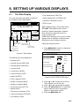
6.1 The Data Display ............................ 6-1
6.2 Position Format .............................. 6-2
6.3 Demo Display ................................. 6-4
7. ALARMS
7.1 Overview ........................................ 7-1
7.2 Arrival Alarm, Anchor Watch Alarm . 7-1
7.3 Cross Track Error (XTE) Alarm ....... 7-2
7.4 Speed Alarm ................................... 7-3
7.5 Trip Alarm ....................................... 7-3
7.6 Water Temperature Alarm ............... 7-4
7.7 Depth Alarm.................................... 7-4
7.8 WAAS/DGPS Alarm........................ 7-4
8. MENU SETTINGS
8.1 GPS SETUP Menu ......................... 8-1
8.2 Units of Measurement .................... 8-4
8.3 Size and Brilliance of Markers ........ 8-5
8.4 Outputting Data .............................. 8-6
8.5 Receiving Data from Personal
Computer ....................................... 8-8
8.6 WAAS/DGPS Setting.................... 8-10
8.7 GPS Monitor Display .................... 8-11
3. MARKS
3.1 Entering Marks................................3-1
3.2 Erasing Marks.................................3-1
3.3 Mark Shape ....................................3-2
3.4 Connecting Marks ...........................3-2
3.5 Entering Event Marks......................3-2
3.6 Event Mark Shape ..........................3-3
3.7 Entering the MOB Mark ..................3-3
9. MAINTENANCE &
TROUBLESHOOTING
9.1 Clearing the Memory ...................... 9-1
9.2 Preventive Maintenance ................. 9-2
9.3 Error Messages .............................. 9-2
9.4 Troubleshooting .............................. 9-4
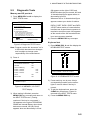
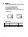
9.5 Diagnostic Tests ............................. 9-5
9.6 Interface Unit IF-2500..................... 9-6
4. NAVIGATION PLANNING
4.1 Entering Waypoints .........................4-1
4.2 Editing Waypoints ...........................4-4
4.3 Erasing Waypoints ..........................4-4
4.4 Entering Routes ..............................4-5
4.5 Erasing Route Waypoints................4-6
4.6 Replacing Route Waypoints............4-7
4.7 Erasing Routes ...............................4-7
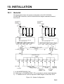
10.1 INSTALLATION
10.1 General....................................... 10-1
10.2 Display Unit ................................ 10-2
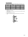
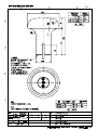
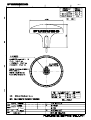
10.3 Antenna Unit ............................... 10-4
10.4 Wiring ......................................... 10-8
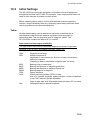
10.5 Initial Settings ............................. 10-9
10.6 Interface Unit IF-2500............... 10-18
10.7 GPS/BEACON
Antenna Distributor MD-GB2.... 10-22
5. SETTING DESTINATION
5.1 Setting Destination..........................5-1
5.2 Cancelling Destination ....................5-5
5.3 Erasing Route Waypoints (flags).....5-6
5.4 Finding Range and Bearing
Between Two Points .......................5-7
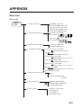
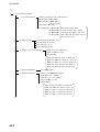
APPENDIX
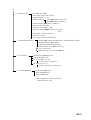
Menu Tree ......................................... AP-1
World Time Standards ....................... AP-3
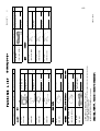
Geodetic Chart List............................ AP-5
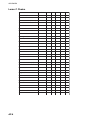
Loran C Chains.................................. AP-6
Decca Chains .................................... AP-7
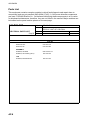
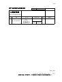
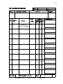
Parts List ........................................... AP-8
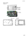
Parts Location.................................... AP-9
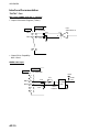
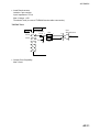
Interface Documentation ................. AP-10
iii
TABLE OF CONTENTS
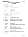
SPECIFICATIONS OF GP-150-DUAL . SP-1
PACKING LISTS.................................... A-1
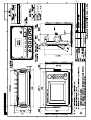
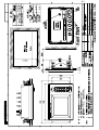
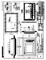
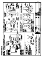
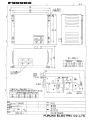
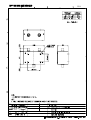
OUTLINE DRAWINGS........................... D-1
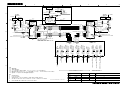
INTERCONNECTION DIAGRAM ...........S-1
INDEX ................................................... IN-1
iv
FOREWORD
A Word to GP-150-DUAL
Owners
Congratulations on your choice of the
FURUNO GP-150-DUAL dual differential
GPS navigation system. We are confident
you will see why the FURUNO name has
become synonymous with quality and
reliability.
For over 50 years FURUNO Electric
Company has enjoyed an enviable reputation
for innovative and dependable marine
electronics equipment. This dedication to
excellence is furthered by our extensive
global network of agents and dealers.
This equipment is designed and constructed
to meet the rigorous demands of the marine
environment. However, no machine can
perform its intended function unless operated
and maintained properly. Please carefully
read and follow the recommended
procedures for operation and maintenance.
We would appreciate hearing from you, the
end-user, about whether we are achieving
our purposes.
Thank you for considering and purchasing
FURUNO equipment.
Features
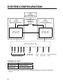
The GP-150-DUAL consists of two dual
differential GPS navigator systems and an
interface unit. Each GPS navigator consists
of a display unit combining a GPS receiver
and video plotter, a GPS antenna. The
interface unit functions to exchange data
between the GPS navigators and external
equipment. A high sensitivity receiver tracks
up to 12 satellites simultaneously. An 8-state
Kalman filter ensures optimum accuracy in
determination of vessel position, course and
speed.
The main features of the GP-150-DUAL are
• Comprehensive navigation data displays
• Storage for 999 waypoints and 30 routes
• Alarms: Waypoint Arrival, Anchor Watch,
Cross track Error, Speed, Water
Temperature, Depth, and Trip
• Man overboard feature records latitude and
longitude coordinates at time of man
overboard and provides continuous
updates of range and bearing to that point.
• Menu-driven operation
• Bright 122 x 92 mm LCD with temperature
compensated tone and brilliance
adjustment
• Power consumption is a low 10 W per
navigator.
• Connection of autopilot (option) - steering
data output to autopilot
• Digital display of water temperature and
depth with connection of echo sounder
having IEC 61162-1/NMEA input
• Memory stores 2,000 points of track and
marks.
• 3D "Highway" display shows ship's track
overlaid on intended course.
• Position may be shown in latitude and
longitude or LOP (Loran or Decca).
• Navaid information (lighthouse data, lighted
buoys, etc.) can be displayed by
downloading database from personal
computer.
• Fully meets the following regulations:
IMO MSC. 112(73), IEC 61162-1 and IEC
61108-1.
Program No.
2051518-01.xx (January, 2006)
v
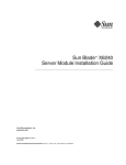
SYSTEM CONFIGURATION
GPS
ANTENNA
GPA-017S/018S/019S
GPS
ANTENNA
GPA-017S/018S/019S
GPS
ANTENNA
GPA-017S/018S/019S
GPS/BEACON
ANTENNA
DISTRIBUTOR
MD-GB2*
DISPLAY UNIT
DISPLAY UNIT
GP-150-DUAL
GP-150-DUAL
INTERFACE UNIT IF-2500
Position, waypoint, etc.
(RS-422/Current loop)
Position, etc.
(Current loop)
Arrival
alarm
Cross track
error alarm
Abnormal receiving
alarm
CATEGORY OF UNITS
Unit
Category
ANTENNA UNIT
Exposed to weather
DISPLAY UNIT
Protected from weather
* When an antenna unit is commonly used, GPS/BEACON Antenna Distributor MD-GB2 is
required.
vi
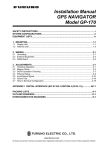
1. OPERATIONAL OVERVIEW
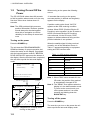
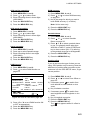
1.1
Control Description
Cursor pad
Shift display and
cursor.
Opens/closes menu;
quits current operation.
Selects display mode.
Registers waypoints
and routes.
Inscribes mark on
the display.
Enlarges display.
Centers ship’s position/cursor
position.
Adjusts display contrast
and brilliance;
changes latitude/longitude
coordinate.
MENU
ESC
NU/CU
ENT
DISPLAY
1
SEL
EVENT
MOB 6
WPT
RTE
GOTO
2
7
Selects display orientation;
registers selections on menus.
Inscribes event mark at
ship’s position; marks man
overboard position.
Sets destination.
3
PLOT
ON/OFF8
ZOOM
4
IN
ZOOM
OUT
9
Shrinks display.
CENTER
5
CURSOR
ON/OFF 0
Turns cursor on/off.
MARK
TONE
CLEAR
POWER
Turns recording and plotting
of ship’s track on/off.
Deletes waypoints and marks;
clears wrong data; silences
audible alarm.
Turns power on/off.
Figure 1-1 Control Panel
1-1
1. OPERATIONAL OVERVIEW
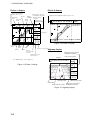
1.2
Turning On and Off the
Power
When turning on the power the following
occurs:
The GP-150-DUAL takes about 90 seconds
to find its position when turned on for the very
first time. Other times it takes about 12
seconds.
12 seconds after turning on the power,
accurate position (in latitude and longitude)
appears on the display.
Note: The GPS provides highly accurate
position information. However, position
should always be checked against
other aids to navigation to confirm
reliability, for the safety of vessel and
crew.
If position could not be found, "NO FIX"
appears at the GPS receiving condition
window. When PDOP (Position Dilution Of
Precision) value exceeds 6 in the 3D mode or
HDOP (Horizontal Dilution Of Precision)
value exceeds 4 in the 2D mode, "DOP"
appears to indicate abnormal fixing and the
position indication is not updated.
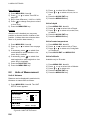
Turning on the power
Press the POWER key.
The unit tests the PROGRAM MEMORY,
SRAM and battery for proper operation and
shows the results on the display. If equipped
with the internal beacon receiver, "BEACON
RCVR INSTALLED" appears at the bottom of
the display. After the test has been completed,
the unit starts up with the last-used display
mode.
PROGRAM MEMORY = OK
SRAM
= OK
Internal Battery
= OK
BEACON RCVR INSTALLED
DATA 3 : DATA OUTPUT
GPS receiving
condition
Several seconds
later
34° 23.456´ N 135° 45.678´ E
30
D3D 100m
SAFE
BRG
234°
[01]
COG
40
50
H
345°
RNG
123 nm
20
WGS84
2nm
SOG
12.3 kt
Figure 1-2 Appearance of display when
turning on the power
1-2
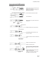
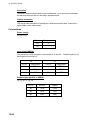
When the satellite signal is being received
normally, one of the indications shown in
Table 1-1 appears depending on equipment
setting and GPS receiver state.
Table 1-1 GPS receiver indication
Indication
Meaning
2D
GPS 2D
3D
GPS 3D
D2D
Differential 2D
D3D
Differential 3D
W2D
WAAS 2D
W3D
WAAS 3D
Note 1: When PDOP value exceeds 6 in the
3D mode, the position fixing method
is automatically changed to 2D.
Note 2: The "DEMO" icon appears when the
display is in the demonstration mode.
To return to the normal mode, turn
off the power and turn it on while
pressing and holding down the
NU/CU ENT key.
Turning off the power
Press the POWER key.
The next time you turn on the power the unit
starts up with the last-used display mode.
1. OPERATIONAL OVERVIEW
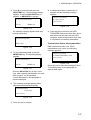
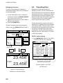
1.3
Adjusting Display
Contrast and Brilliance
1) Press the TONE key. The display shown
in Figure 1-3 appears.
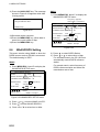
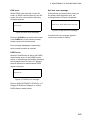
1.4
Display Mode
1) Press the DISPLAY SEL key. The display
shown in Figure 1-4 appears.
Select Display
Plotter 1
[-]
Plotter 2
[+]
Highway
Tone:
17 (0~31)
Brilliance:
7 (0~7)
Navigation
Data
(DATUM: WGS-84)*
MENU
MENU
:
:
Select
:
Escape
Escape
Figure 1-3 Screen for adjustment of display
tone and brilliance
or . Current
2) To adjust tone, press
setting and setting range (0-31) are
shown to the right of " ".
3) To adjust brilliance, press
or .
Current setting and setting range (0-7) are
shown to the right of " ".
*Shows currently selected geodetic
chart datum.
Figure 1-4 Screen for selection of display
mode
or
to
2) Press the DISPLAY SEL key,
select display mode. (When the DISPLAY
SEL key is pressed, the display mode
changes in sequence shown below.)
Selected display mode appears.
Plotter 1
Note 1: Operate cursor pad within 10
seconds after pressing the TONE
key. Otherwise, the screen for
adjustment of tone and brilliance will
be cleared.
Note 2: If the display is turned off with
minimum tone it will be blank at the
next power up. When this occurs
press the TONE key continuously to
adjust tone.
Plotter 2
Data
Highway
Navigation
Sample displays of each display mode are
shown in the figures on the next several
pages.
1-3
1. OPERATIONAL OVERVIEW
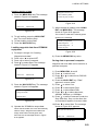
Plotter 1 display
Plotter 2 display
Cursor position data,
when cursor is on
Bearing from own ship
to destination waypoint
Ship's position appears when cursor is off.
RAIM
Course
GPS receiving
Own ship's
reliability*
bar
condition
track
Own ship
Alarm
Distance for
mark
range
RAIM reliability
D3D 100m
34° 23.456´ N 135° 45.678´ E SAFE
30
D3D 100m
34° 23.456´ N 135° 45.678´ E SAFE
30
44°
[01]
COG
40
[01]
BRG
50
H
32°
40
Waypoint
50
H
BRG TO +
123°
20
WGS84
2.00 nm
RNG TO +
11.5 nm
20
WGS84
2 nm
Figure 1-6 Plotter 2 display
Horizontal
range
Course
Grid
width
Course over ground
Course
Cursor
Highway
Range
from own ship
to cursor
Bearing from own
ship to cursor
display
Bearing from own ship to
destination waypoint
Position
*: For RAIM function, refer to page 8-1.
Course over ground
34° 23.456´ N 135° 45.678´ E
D3D 100m
SAFE
BRG
34°
Figure 1-5 Plotter 1 display
COG
45°
RNG
0.35nm
SOG
12.3 kt
WGS84
Own ship mark
Speed over ground
North mark
Cross track error scale
Range from own ship to
destination waypoint
Figure 1-7 Highway display
1-4
1. OPERATIONAL OVERVIEW
Navigation display
2) Autopilot connected, automatic mode
1) No autopilot
TO;
Cross track
error meter
Bearing from own
ship to destination
waypoint
Bearing
scale
Destination
waypoint no.
ETA
VTD
10.3kt
0.1nm
S
RNG
123 nm
0.1nm
123nm
Hdg
TRIP
Str
123° P 23° 789 nm
Auto
Auto mode
Heading
789nm
Range from own
ship to destination
waypoint
Rudder angle
Rudder
angle
P: Port
S: Starboard
TRIP
Trip
distance
Time To Go
(3days17hrs45min)
Cross track
error indication
Auto Pilot
RNG
0.1nm
TTG
Estimated Time of
Arrival (15th23:45)
Cross track
error scale
S
3D
17H 45M
15
23:45'
10.3 kt
63°
123°
COG:
12.3 kt
BRG
0.1nm
VTD
BRG:
100m
SOG
N
63°
COG
123°
SOG
N
Speed over ground
D3D
SAFE
E
E
100m
12.3 kt
Velocity To
Destination
TO; 012
D3D
SAFE
012
Figure 1-9 Navigation display, with autopilot
connected, automatic mode
3) Autopilot connected, modes other than
automatic mode
(manual, nav, etc.)
TO; -
D3D
SAFE
--
E
Waypoint
100m
SOG
12.3 kt
N
VTD
BRG:
10.3 kt
63°
123°
COG:
0.1nm
VTD
S
SOG
Auto Pilot
Man
Man: Manual mode
Nav: Nav mode
Other:---
Figure 1-8 Navigation display,
no autopilot
Hdg
AP CSE
0.1nm
Str
123°
TRIP
123° P 23° 789 nm
Heading
Rudder angle
Autopilot-set
course
Figure 1-10 Navigation display, autopilot
connected, modes other than
the automatic mode
1-5
1. OPERATIONAL OVERVIEW
Data display
Transmitting data
Refer to Chapter 6 for user-defined window
setting. The ZOOM icon can be displayed by
pressing the CURSOR ON/OFF key.
To mutually transmit data, do the following:
Position in latitude and
longitude or LOPs
U: UTC
J: JST
S: Ship's time
Fixing date and time*
D3D
SAFE
JAN 12, 2006 23:59'59" U
POSITION
WGS84
100m
12° 23.456' N
123° 23.456' E
RNG
TO : 001
BRG
31.23
SOG
123.4°
kt
: 002
NEXT
COG
12.3
MARINE
POINT1
223.4°
nm
Zoom icon
MARINE
POINT2
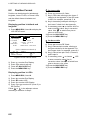
1) Press the MENU ESC key to display the
MAIN menu.
MAIN MENU
1. DISPLAY SETUP
2. TRACK/MARK SETUP
3. ERASE TRACK/MARK
4. ALARM SETTINGS
5. MANUAL CALCULATION
6.
7. GPS MONITOR
8. SELF TESTS
9. SYSTEM SETTINGS
ENT: Enter
User-defined
display data #1
User-defined
display data #4
User-defined
display data #2
User-defined
display data #3
User-defined
display window
Figure 1-11 Data display mode
*: "--" appears until position is found. If fixing
error occurs the time indication freezes.
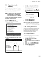
1.5
MENU: Escape
Current destination waypoint
Next destination waypoint
Transmitting Data
The GPS navigators share the data listed
below when transmitting data to each other.
Any action initiated against those data is
automatically repeated on the other navigator.
For example, if you register waypoint 27 on
one navigator it will be registered on the other
navigator under the same waypoint number.
• Alarm settings, alarm buzzer
• Destination data
• Disabled satellite data
Figure 1-12 MAIN menu
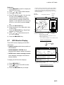
2) Press the 9 key to display the SYSTEM
SETTINGS menu.
SYSTEM SETTINGS
1. PLOTTER SETUP
2. UNIT SETUP
3. DATA 1, 3 OUTPUT SETUP
4. DATA TRANSFER
5. DATA 4 I/O SETUP
6. GPS SETUP
7. DGPS SETUP
8. LOP SETUP
9. CLEAR MEMORY
ENT: Enter
MENU: Escape
Figure 1-13 SYSTEM SETTINGS menu
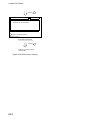
3) Press the 4 key to select DATA
TRANSFER.
DATA TRANSFER
Transmit Data
All
Stop
Start
• Error messages
• MOB/Event mark data
• Route data
• Waypoint data
: Select
Note: This operation is necessary after
receiving waypoint data through the
DATA 4 port (Page 10-14).
1-6
ENT: Enter
MENU: Escape
Figure 1-14 DATA TRANSFER menu
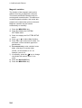
1. OPERATIONAL OVERVIEW
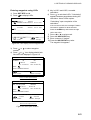
4) Press
to select All and press the
NU/CU ENT key. The following message
appears. Press the NU/CU ENT key to
transmit, or MENU ESC to escape.
Are you sure to transmit ?
ENT: Yes
8) If transmission failed, transmission is
stopped and the following message
appears.
Failed in transmitting
Try again please
Press any key
MENU: No
Figure 1-19
Figure 1-15
The following message appears while data
is being transmitted.
Now transmitting data
9) Press any key to return to the DATA
TRANSFER menu and select Stop. Since
data will be not the same on both GPS
navigator, repeat this procedure from step
4 until data is successfully transmitted.
Transmission failure during operation
MENU: Stop
Figure 1-16
5) To stop transmitting data, press the
MENU ESC key. The following display
appears.
Data is transmitted only once. When
transmission error occurs, the following
message appears.
Failed in transmitting
Try "DATA TRANSFER" menu
Press any key
Are you sure to stop ?
ENT: Yes
MENU: No
Figure 1-17
Press the NU/CU ENT key to stop. In this
case, data is partially transmitted to the other
GPS navigator. You should follow
"Transmsitting data" in this paragraph to
transmit data again.
Figure 1-20
Press any key to erase the message. Follow
"Transmitting data" in this paragraph to
transmit data again.
6) The following message appears when
data was transmitted successfully.
Transmitting ended
successfully
Press any key
Figure 1-18
7) Press any key to escape.
1-7
1. OPERATIONAL OVERVIEW
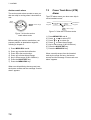
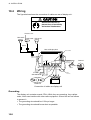
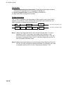
1.6
The Interface Unit
The Interface Unit IF-2500 outputs data
received from the navigators to external
equipment. Operational status is shown by
the LEDs on the unit. For further details, see
the chapter on installation. For how to select
data to output, see paragraph 8.4 Outputting
Data.
Output data conventions
Since both navigators output data to the
IF-2500 (through two ports on the interface)
confusion would reign if it were to try to
output two sets of mostly identical data.
Therefore, data output is governed by the
following rules:
• When both navigators are outputting data
correctly, data received at the port having
higher priority is output.
• When the GPS abnormal receive signal is
received at the port having higher priority,
data received from the other port is output.
• 30 seconds after data received at the port
having higher priority becomes normal, the
interface unit resumes outputting data
received from that port.
• When data from both navigators is in error,
data received at the port having higher
priority is output.
• Arrival alarm signal or cross track error
alarm is converted to a contact signal and
output when received at the port having
higher priority.
• When no data is received from one or both
navigators, a contact signal is output.
1-8
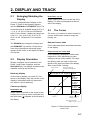
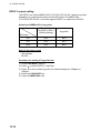
2. DISPLAY AND TRACK
2.1
Enlarging/Shrinking the
Display
You may enlarge/shrink the display on the
Plotter 1, Plotter 2 and Highway displays,
with the ZOOM IN and ZOOM OUT keys. The
horizontal range is available among 0.25, 0.5,
1, 2, 4, 8, 16, 32, 64, 128 and 192 nautical
miles. For the Plotter 1 display the ranges are
0.36, 0.71, 1.42, 2.84, 5.69, 11.38, 22.76,
45.51, 91.02, 182.04 and 273.07 nautical
miles.
The ZOOM IN key enlarges the display and
the ZOOM OUT key shrinks it. Each time a
zoom key is pressed the horizontal range
appears at the center of the display for about
one second.
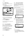
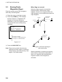
2.2
Display Orientation
Display orientation can be selected on the
Plotter 1 and Plotter 2 displays, with the
NU/CU ENT key. Two display orientations are
available: north-up and course-up.
North-up display
In the north-up display, true north (0°) is at
the top of the display. Own ship moves on the
display in accordance with true speed and
true motion. Land is stationary.
Destination not set
Ship's heading or course is at the top of the
display. The north mark appears at the left
side of the display.
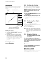
2.3
The Cursor
The cursor (+) functions to select location for
a mark; erase marks; measure range and
bearing, etc.
Data and cursor state
Cursor state determines what data are shown
on the display.
Cursor turned on, cursor data
Cursor position is displayed in latitude and
longitude or LOPs (depending on menu
setting) at the top of the display. The range
and bearing from own ship to the cursor
appear at the right hand side of the display,
when in the Plotter 1 display.
Cursor mark
D3D 100m
34° 23.456´ N 135° 45.678´ E SAFE
BRG
234°
COG
345°
BRG TO +
Course-up display
123°
Destination set
Ship’s course is upward on the screen at the
moment the course-up mode is selected and
the north mark ( ) appears at the left side of
the display.
Cursor position in
latitude and longitude
RNG TO +
11.5 nm
WGS84
2.0 nm
Cursor
Range from own
ship to cursor
Bearing from own
ship to cursor
Figure 2-1 Data displayed when the
cursor is on
2-1
2. DISPLAY AND TRACK
Cursor turned off
2.4
Ship's position (in latitude and longitude or
LOPs), speed and course appear on the
display.
The display can be shifted on the Plotter 1
and Plotter 2 displays, with the CURSOR
ON/OFF key. When own ship tracks off the
display it is automatically returned to the
screen center.
Own ship
mark
Own ship position
in latitude and longitude
34° 23.456´ N 135° 45.678´ E
D3D 100m
SAFE
BRG
234°
COG
345°
RNG
123°nm
1) Press the CURSOR ON/OFF key to turn
off the cursor.
2) Press the cursor pad continuously. The
display shifts in the direction of the arrow
pressed.
2.5
SOG
12.3 kt
Course
Speed
Figure 2-2 Data displayed
when the cursor is turned off
Shifting the cursor
1) Press the CURSOR ON/OFF key to turn
on the cursor.
2) Press the cursor pad to shift the cursor.
The cursor moves in the direction of the
arrow pressed. When the cursor reaches
the edge of the display, the display shifts
in the direction opposite of the arrow
pressed.
Centering the cursor
Press the CENTER key.
Shifting the Display
Centering Own Ship's
Position
1) Press the CURSOR ON/OFF key to turn
off the cursor.
2) Press the CENTER key.
Note: When own ship’s position reaches an
edge of the screen, the display moves
to set own ship’s position center of the
display.
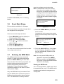
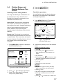
2.6
Stopping/Starting
Plotting and Recording
of Track
The GP-150-DUAL stores 2,000 points of
track and marks. When the memory becomes
full the oldest track is erased to make room
for the latest.
Procedure
Press the PLOT ON/OFF key to start/stop
recording and plotting of track.
When plotting is resumed
"Resuming track plot" appears at the center
of the display for about three seconds.
2-2
2. DISPLAY AND TRACK
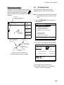
When plotting is stopped
2.7
"Stopping track plot" appears at the center of
the display for about three seconds and " H "
appears at the left side of the display. (" H "
does not appear on the Navigation and Data
displays.)
The track stored in the memory and
displayed on the screen can be erased.
Hold icon
(appears while recording
of track is stopped)
34° 23.456´ N 135° 45.678´ E
D3D 100m
SAFE
BRG
234°
COG
345°
H
Recording
is stopped.
RNG
123
nm
SOG
12.3 kt
This portion of track
does not appear on
the display
Own ship
Recording of
track started
Ship’s track
while recording is
stopped
Recording of track
turned off
Figure 2-3 Track not plotted or
recorded when plotting is stopped
Erasing Track
Note: Track cannot be restored once erased.
Be absolutely sure you want to erase
track.
1) Press the MENU ESC key to show the
MAIN MENU.
MAIN MENU
1. DISPLAY SETUP
2. TRACK/MARK SETUP
3. ERASE TRACK/MARK
4. ALARM SETTINGS
5. MANUAL CALCULATION
6.
7. GPS MONITOR
8. SELF TESTS
9. SYSTEM SETTINGS
ENT: Enter
MENU: Escape
Figure 2-4 MAIN menu
2) Press 3 to select ERASE TRACK/MARK.
ERASE TRACK/MARK
Erase Track
No
Yes
Erase Mark
No
Yes
Track Pts. Used:
345/1000 Pt
Mark Pts. Used:
123/1000 Pt
: Select
MENU: Escape
Figure 2-5 ERASE TRACK/MARK menu
3) Press
to select Erase Track.
4) Press
to select Yes. The message
shown in Figure 2-6 appears.
2-3
2. DISPLAY AND TRACK
Are you sure to erase ?
ENT: Yes
MENU: No
Figure 2-6 Prompt for
erasure of track
to select Track Rec.
3) Press
4) Press
to select Time.
5) Enter plotting interval in four digits. To
enter 30 seconds, for example, press 0, 0,
3, 0.
6) Press the NU/CU ENT key.
7) Press the MENU ESC key.
5) Press the NU/CU ENT key.
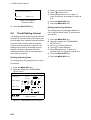
Plotting interval by distance
2.8
The setting range for plotting by distance is
0.01 to 99.99 nautical miles. To plot all track,
enter 00.00.
Track Plotting Interval
The plotting interval determines both how the
track will be reconstructed on the display and
track storage time. A shorter interval provides
more accurate reconstruction of track line,
however total storage time is reduced. The
plotting interval can be selected by time or
distance. Plotting by distance offers the
advantage that the track is not stored when
the vessel is anchored.
Plotting interval by time
The setting range for plotting by time is 00 to
60 minutes.
1) Press the MENU ESC key.
2) Press 2 to display the TRACK/MARK
SETUP menu.
TRACK/MARK SETUP
Track Rec
Time
(01’00)
Dist
(00.50nm)
Mark Shape
Mark Line
Event Mark
: Select
ENT: Enter
MENU: Escape
Figure 2-7 TRACK/MARK SETUP menu
2-4
1) Press the MENU ESC key.
2) Press 2 to display the TRACK/MARK
SETUP menu.
3) Press
to select Track Rec.
4) Press
to select Distance.
5) Enter plotting interval. To enter 0.1
nautical miles, for example, press 0, 0, 1.
6) Press the NU/CU ENT key.
7) Press the MENU ESC key.
2. DISPLAY AND TRACK
2.9
Apportioning the
Memory
The memory holds 2,000 points of track and
marks and may be apportioned as you like.
The default memory setting stores 1,000
points each of track and marks.
Note: All data are erased when the memory
apportion setting is changed, even
when the previous value is reentered.
To store 1,500 points of track and 500 marks,
for example, do the following:
1) Press the MENU ESC key.
2) Press 9 to display the SYSTEM
SETTINGS menu.
SYSTEM SETTINGS
1. PLOTTER SETUP
2.
2.
UNIT
SETUP
2. UNIT
UNITSETUP
SETUP
MENU: Escape
3) Press 1 to display the PLOTTER SETUP
menu.
PLOTTER SETUP
Memory Apportion
Trk = 1000 / 2000Pt
Mag Variation
Calculation
True
Man
(00° E)
R.L
G.C
RNG
User defined #2
SOG
User defined #3
BRG
COG
User defined #4
ENT: Enter
Mag
Auto
(07° W)
User defined #1
Are you sure to change ?
ENT: Yes
MENU: No
Figure 2-10
7) Press the NU/CU ENT key.
8) Press the MENU ESC key.
Note: Two display units in a system should
be set the same points for memory
setting store to share waypoints data.
Ship's course and bearing to waypoint may
be displayed in true or magnetic bearing.
Magnetic bearing is true bearing plus (or
minus) earth's magnetic deviation.
Figure 2-8 SYSTEM SETTNGS menu
Bearing Ref.
Setting erases all data!
2.10 Bearing Reference
3. DATA 1, 3 OUTPUT SETUP
4. DATA TRANSFER
5. DATA 4 I/O SETUP
6. GPS SETUP
7. DGPS SETUP
8. LOP SETUP
9. CLEAR MEMORY
ENT: Enter
4) Press
to select Memory Apportion.
5) Enter amount of track to store, in four
digits. To store 1,500 track points, for
example, press 1, 5, 0, 0.
6) Press the NU/CU ENT key, or
or .
You are asked if it is all right to erase all
data.
True or magnetic bearing
The default setting displays true bearings.
1) Press the MENU ESC key.
2) Press 9 to display the SYSTEM
SETTINGS menu.
3) Press 1 to display the PLOTTER SETUP
menu.
4) Press
or
to select Bearing Ref.
5) Press
or
to select True or Mag.
6) Press the NU/CU ENT key.
7) Press the MENU ESC key.
MENU: Escape
Figure 2-9 PLOTTER SETUP menu
2-5
2. DISPLAY AND TRACK
Magnetic variation
The location of the magnetic north pole is
different from the geographical north pole.
This causes a difference between the true
and magnetic north direction. This difference
is called magnetic variation, and varies with
respect to the observation point on the earth.
Magnetic variation may be entered
automatically or manually.
1) Press the MENU ESC key.
2) Press 9 to display the SYSTEM
SETTINGS menu.
3) Press 1 to display the PLOTTER SETUP
menu.
4) Press
or
to select Mag Variation.
5) Press
or
to select Auto or Man. For
automatic, current variation appears in
parentheses.
6) For manual entry, enter variation in two
digits, referring to a nautical chart
(00-99°). If the variation is 10°, for
example, press 1, 0.
key to change
7) If necessary, press the
coordinate from east to west or vice
versa.
8) Press the NU/CU ENT key.
9) Press the MENU ESC key.
2-6
3. MARKS
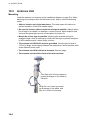
3.1
Entering Marks
3.2
Erasing Marks
Marks can be inscribed on the Plotter 1 and
Plotter 2 displays, in one of 12 mark shapes.
Further, marks can be connected with lines.
Note: When the mark memory becomes full
no marks can be entered. When this
occurs, the buzzer sounds and the
message shown below appears on the
display for three seconds. To enter a
mark when the mark memory is full,
erase unnecessary marks.
Can’t save mark
Memory full
Figure 3-1
CAUTION
All marks, including event marks and the
MOB mark, are erased on the ERASE
MARK menu. Be absolutely sure you want
to erase all marks; erased marks cannot
be restored.
Erasing individual marks
1) Place the cursor on the mark to erase.
2) Press the CLEAR key.
Erasing all marks
1) Press MENU ESC and 3 to display the
ERASE TRACK/MARK menu.
ERASE TRACK/MARK
Entering marks
At own ship position
Erase Track
No
Yes
Erase Mark
No
Yes
1) Press the CURSOR ON/OFF key to turn
off the cursor.
2) Press the MARK key.
Track Pts. Used:
Mark Pts. Used:
At cursor intersection
1) Press the CURSOR ON/OFF key to turn
on the cursor.
2) Operate the cursor pad to place the
cursor on the location for the mark.
Select the mark shape you want, referring
to paragraph 3.3.
3) Press the MARK key.
345/1000 Pt
123/1000 Pt
: Select
MENU: Escape
Figure 3-2 ERASE TRACK/MARK menu
2) Press
3) Press
to select Erase Mark.
to select YES.
Are you sure to erase ?
ENT: Yes
MENU: No
Figure 3-3
4) Press the NU/CU ENT key.
5) Press the MENU ESC key.
3-1
3. MARKS
3.3
Mark Shape
3.5
13 mark shapes are available. Select mark
shape as follows:
1) Press MENU ESC and 2 to display the
TRACK/MARK SETUP menu.
TRACK/MARK SETUP
Track Rec
Time
(01’00)
Dist
(00.50nm)
Mark Shape
Mark Line
Event Mark
: Select
ENT: Enter
MENU: Escape
Figure 3-4 TRACK/MARK SETUP menu
or
to select Mark Shape.
2) Press
3) Press
or
to select mark shape
desired.
4) Press the NU/CU ENT key.
5) Press the MENU ESC key.
The next mark entered will be inscribed in the
shape selected here.
3.4
Connecting Marks
Marks can be connected with lines. Three
types of connection lines are available and
the "•" setting disables connection of lines.
1)
2)
3)
4)
5)
Press MENU ESC and 2.
Press
or
to select Mark Line.
Press
or
to select other than "•".
Press the NU/CU ENT key.
Press the MENU ESC key.
3-2
Entering Event Marks
Event marks can denote any important
present position. 99 event marks can be
saved, and the unit automatically numbers
them from 01 to 99.
Event marks are mutually entered when the
navigators are sharing data.
Note 1: When the mark memory becomes
full no event marks can be entered.
When this occurs, the buzzer
sounds and the message shown
below appears on the display for
three seconds to alert you. To enter
an event mark when the mark
memory is full, erase unnecessary
event marks.
Can’t save mark
Memory full
Figure 3-5
Note 2: Event marks cannot be entered
when there is no position data.
When this occurs, the buzzer
sounds and the message shown
below appears on the display for
three seconds to alert you. Check
that the antenna cable is tightly
connected.
Can’t save event/MOB
No position data
Figure 3-6
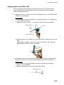
To enter an event mark;
1) Press the EVENT MOB key less than
three seconds. The position at the exact
moment the key is pressed is saved as an
event position.
3. MARKS
Saved event position
34° 40.123’ N
135° 21.123’ E
Figure 3-7
To erase event marks, see "3.2 Erasing
Marks".
when the navigators are sharing data.
Note: The MOB mark cannot be entered
when there is no position data. When
this occurs, the buzzer sounds and the
message shown below appears on the
display for three seconds to alert you.
Check that the antenna cable is tightly
connected.
Can’t save event/MOB
3.6
Event Mark Shape
Event marks are available in 10 shapes.
Event mark shape is mutually changed when
the navigators are sharing data.
Select event mark shape as follows.
1) Press MENU ESC and 2 to display the
TRACK/MARK SETUP menu.
2) Press
to select Event Mark.
3) Press
or
to select event mark
shape desired.
4) Press the NU/CU ENT key.
5) Press the MENU ESC key.
The next event mark entered will be inscribed
in the shape selected here.
3.7
Entering the MOB Mark
The MOB mark denotes man overboard
position. To mark man overboard position,
press the EVENT MOB key for more than
three seconds. When the key is pressed, the
position at the exact moment the key is
pressed automatically becomes the
destination. Further, the plotter display
replaces the display in use when it is other
than a plotter display.
Only one MOB mark may be entered. Each
time the MOB mark is entered the previous
MOB mark and its position data are written
over. The MOB mark is mutually entered
No position data
Figure 3-8
1) Press the EVENT MOB key for at least
three seconds.
The MOB mark ("M") is entered at the MOB
position and the message shown in Figure 3-9
appears.
Saved MOB position
Are you sure to change course
to MOB position ?
ENT: Yes
MENU: No
Figure 3-9
2) Press the NU/CU ENT key. If the display
in use is Highway, Navigation or Data,
they are automatically replaced by the
plotter display.
Note: You may cancel MOB position as
destination by pressing the MENU
ESC key instead of the NU/CU ENT
key at step 2. Note that the MOB mark
remains on the display.
Erasing the MOB mark
See "3.2 Erasing Marks". (MOB mark cannot
be erased with the cursor.) The MOB mark is
mutually erased when the navigators are
sharing data.
3-3
3. MARKS
This page is intentionally left blank.
3-4
4. NAVIGATION PLANNING
4.1
Entering Waypoints
In navigation terminology a waypoint is a
particular location on a voyage whether it be
a starting, intermediate or destination
waypoint.
The GP-150-DUAL can store 999 waypoints,
numbered from 001-999. Waypoints can be
registered four ways:
• by cursor
• by MOB position or event position
• at own ship's position, and
• through the waypoint list.
Waypoints are mutually entered when the
navigators are sharing data.
Entering waypoints by the cursor
1) Press the WPT RTE key to show the
Waypoint/Route menu.
Waypoint/Route
1. Cursor
2. MOB/Event Position
3. Own ship Position
4. Waypoint List
5. Route Planning
3) Use the cursor pad to place the cursor on
the location desired for the waypoint.
4) Press the NU/CU ENT key.
A window similar to the one shown in Figure
4-3 appears. The waypoint's position and
date and time registered appear on the first
and second lines. Waypoints are
automatically given the youngest empty
waypoint number and this number appears
on the third line. You may, however, assign a
different number. If the waypoint shares the
same position with a mark, the mark's
position and date and time entered are
registered as waypoint data.
If the waypoint memory is full, the waypoint
number line in the window is blank. In this
case waypoints cannot be entered unless a
waypoint is written over or erased.
30° 12.345’ N 135° 23.456’ W
AUG 12’ 03 12 : 34U
No. : 1
123
Mark :
Cmnt :
: Cursor
ENT: Enter
: Cursor
ENT: Enter
MENU: Escape
Figure 4-3
MENU: Escape
Figure 4-1 Waypoint/Route menu
2) Press 1 to select Cursor. The following
display appears.
Place cursor on desired location
ENT: Enter
: Column
MENU: Escape
Figure 4-2
The display changes to Plotter 2 when the
Highway, Navigation or Data mode is in use.
The remaining steps show how to change
waypoint number, choose mark shape and
enter a comment. If you do not need to
change these items, press the NU/CU ENT
to register the waypoint under the number
shown and the current waypoint mark shape.
You may also choose the waypoint item to
change by pressing
or
and following
the appropriate step in this procedure.
5) Enter waypoint number, in three digits
(001-999).
4-1
4. NAVIGATION PLANNING
6) Press
to select waypoint mark shape.
The following display appears.
: Cursor
MENU: Escape
ENT: Enter
Figure 4-4 Screen for selecting
waypoint mark shape
7) Press
or
to select mark shape.
8) Press the NU/CU ENT key. The display
shown in Figure 4-5 appears.
A
ABCDE FGHIJ KLMNO PQRST UVWXYZ
abcde
fghij
klmno
pqrst
Control is returned to the last-used display
mode.
When the waypoint number entered at step 5
already exists, the message shown in Figure
4-4 appears if the waypoint is part of the
current destination or route or is part of a
route. If you want to write over the waypoint
and its data, press the NU/CU ENT key. To
change waypoint number, press the MENU
ESC key.
1st line
Are you sure to change ?
ENT: Yes
MENU: No
uvwxyz
1234567890 _#%’()+-./:;<=>?
ENTER
COMMENT: _ _ _ _ _ _ _ _ _ _ _ _
: Cursor
ENT: Set
MENU: Escape
Figure 4-5 Screen for entry
of comment for waypoint
9) You may enter a comment, using up to
12 alphanumeric characters.
1 Press the cursor pad to select
alphanumeric character.
2 Press the NU/CU ENT key. Selected
character appears on the COMMENT
line.
• To create a space, select "_".
• Numeric data can be input directly by
pressing numeric keys.
• To clear wrong data, press the CLEAR
key.
Repeat steps 1 and 2 to complete
the comment.
4 Select ENTER and press the NU/CU
ENT key.
3
10) Press the NU/CU ENT key.
4-2
This wpt is GOTO
This wpt is in registered route
This wpt is in selected route
Figure 4-6
Note: If you fail to enter waypoint number,
"Enter waypoint number" appears on
the display for three seconds.
4. NAVIGATION PLANNING
Entering waypoints by MOB
position/event position
Entering waypoints at own ship's
position
The MOB position or an event position can
be registered as a waypoint. Event marks
are numbered from 01 to 99; 01 is the latest
event mark.
Note: When there is no position data, you
cannot register a waypoint at own
ship's position. The buzzer sounds
and the following message appears.
Note: You cannot register a MOB position or
event position when there are no MOB
positions or event positions saved.
The buzzer sounds and the message
shown in Figure 4-7 appears for three
seconds to alert you.
No MOB/event data in memory
Figure 4-7
1) Press the WPT/RTE key.
2) Press 2 to select MOB/Event Position.
The display shown in Figure 4-8 appears.
[MOB] Displaying MOB data
34° 12.345’ N 130° 23.456’ E
AUG 12’ 94 19 : 25U
[#01] Displaying event data
:Recall
N 130° 23.456’ E
34° 12.345’
ENT:Enter
AUG
12’ 03 19 : 25U
MENU:Escape
: Paging
ENT: Enter
MENU: Escape
No position data
Figure 4-9
1) Press the WPT/RTE key.
2) Press 3 to select Own Ship Position.
3) Follow steps 5 through 11 in "Entering
waypoints by the cursor" on page 4-1.
Entering waypoints through the
waypoint list
1) Press the WPT/RTE key.
2) Press 4 to display the waypoint list.
to select position format;
3) Press
latitude and longitude or LOP.
WAYPOINT LIST (L/L)
001 34° 12.345’ N 130° 23.456’ W
MARINE POINT AUG 12’ 03 12 : 35U
002 36° 12.345’ N 135° 23.456’ W
A POINT
003
°
.
’N
004
°
.
’N
AUG 13’ 03 13 : 45U
°
. ’W
Figure 4-8
3) Press
or
to display the MOB
position or event position to register as a
waypoint.
4) Press the NU/CU ENT key.
5) Follow steps 5 through 11 in "Entering
waypoints by the cursor" on page 4-1.
: L/L’ LOP
ENT: Enter
°
.
’W
: Edit
MENU: Escape
Figure 4-10
4) Press
or
to select waypoint
number.
5) Press
or
to enter position. The
display should now look something like
Figure 4-11.
4-3
4. NAVIGATION PLANNING
4.2
Edit = Waypoint : 001
_ _° _ _._ _ _’ N _ _ _°_ _._ _ _’ W
Mark : __
Cmnt :
: Cursor
ENT: Enter
: Column
MENU: Escape
Figure 4-11
6) Enter latitude and longitude. To enter
34°12.345' N 135°23.456' E, for example,
press;
, 3, 4, 1, 2, 3, 4, 5
, 1, 3, 5, 2, 3, 4, 5, 6
To change N to S or E to W, press
Editing Waypoints
Waypoints are mutually edited when the
navigators are sharing data.
1) Press WPT RTE and 4.
2) Press
or
to select waypoint to
edit.
3) Press .
4) Edit the contents of the waypoint.
5) Press the NU/CU ENT key. The message
shown in Figure 4-12 appears if the
waypoint is currently selected as
destination, is part of a route, or is in the
route currently selected as destination.
.
1st line
7) Press .
8) Press
or
to select mark.
9) Press the NU/CU ENT key.
10) Enter comment.
11) Press the NU/CU ENT key twice.
Are you sure to change ?
ENT: Yes
The waypoint list reappears. Waypoint
position and date and time the waypoint was
entered appear on the list.
MENU: No
This wpt is GOTO
This wpt is in registered route
This wpt is in selected route
12) To enter another waypoint through the
waypoint list, repeat steps 4-11.
13) Press the MENU ESC key to finish.
Figure 4-12
6) Press the NU/CU ENT key.
Enter new data, referring to "4.1 Entering
Waypoints".
7) Press the MENU ESC key.
4.3
Erasing Waypoints
Waypoints are mutually erased when the
navigators are sharing data.
Erasing waypoints by the cursor
1) Place the cursor on the waypoint to
erase.
2) Press the CLEAR key.
4-4
4. NAVIGATION PLANNING
Erasing waypoints through the
waypoint list
1) Press WPT RTE and 4.
2) Press
or
to select waypoint to
erase.
3) Press the CLEAR key. The message
shown in Figure 4-13 appears if the
waypoint is currently selected as
destination, is part of a route, or is in the
route currently selected as destination.
1st line
Are you sure to erase ?
ENT: Yes
MENU: No
This wpt is GOTO
This wpt is in registered route
This wpt is in selected route
Figure 4-13
Note: All waypoint marks (as well as all
other marks) and their data can be
erased collectively by clearing the
Plotter memory. For further details,
see page 9-1.
4) Press the NU/CU ENT key.
Note: To cancel erasure, press the
MENU ESC key instead of the
NU/CU ENT key. The waypoint list
appears.
5) Press the MENU ESC key.
4.4
Entering Routes
Often a trip from one place to another
involves several course changes, requiring a
series of route points which you navigate to,
one after another. The sequence of
waypoints leading to the ultimate destination
is called a route. The GP-150-DUAL can
automatically advance to the next waypoint
on a route, so you do not have to change the
destination waypoint repeatedly.
The GP-150-DUAL can store 30 routes and
each route may contain up to 30 waypoints.
Routes can be registered while in the Plotter
1 or Plotter 2 display mode. Routes are
mutually registered when the navigators are
sharing data.
Entering routes
1) Press the WPT/RTE key.
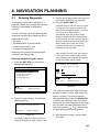
2) Press 5 to select Route Planning. The
route list appears.
ROUTE LIST
No. PTS Total Dist.
TTG
Remarks
01 30 1234 . 56 nm 12D15H28M UseFwd
02 25 234 . 56 nm 2D08H35M
03 30 *999. 99 nm *9D*9H*9M
.
nm
04
D H M
30
05
6543 . 21 nm 34D23H45M
.
nm
06
D H M
: Route No.
ENT: Enter
: Edit
MENU: Escape
Remarks
Use: In use
Fwd: Traverse waypoints in forward order
Rvs: Traverse waypoints in reverse order
Figure 4-14 Route list
3) Press
or
number.
4) Press .
to select an empty route
The route planning/waypoint list window
appear as shown in Figure 4-15. The
waypoint list window lists the position and
data for each registered waypoint. No
position or data appears for empty waypoints.
4-5
4. NAVIGATION PLANNING
2 Using previously registered waypoints
ROUTE : 01 (In Use , REVERSE)
skip Distance TTG
Trial Speed : Auto
01
EN
EN
02
001
Man (012.0kt)
. nm D
. nm D
M
M
H
H
Route
editing
screen
34° 12.345’ N 130° 23.456’ E
MARINE POINT AUG 12’ 03 12: 35U
002 36° 12.345’ N 135° 23.456’ E
AUG 13’ 03 13 : 45U
A POINT
: RTE ↔ WPT CLEAR: Delete
ENT: Enter MENU: Escape
Waypoint
list
Use: In use
Fwd: Traverse waypoints in forward order
Rvs: Traverse waypoints in reverse order
Figure 4-15 Route editing screen
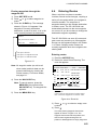
5) If required, press
to choose Trial
Speed to enter the speed by which to
calculate time-to-go.
6) Press
or
to select Auto or Man.
Auto: Current average speed is used to
calculate the time-to-go.
Manual: Entered speed is used to calculate
the time-to-go. Enter speed and press .
Route waypoints may be registered two
ways: entering waypoint number directly or
through the route editing screen. Follow 1
or 2 below.
1 Entering waypoint number directly
7) Enter waypoint number, in three digits.
The cursor shifts to the "Skip" window.
The procedure for skipping a waypoint is
shown on page 5-4. For now, go to the
next step.
8) Press
to continue. If the waypoint
entered in step 7 does not exist, you are
informed that the waypoint does not exist
and entry is cancelled.
9) Enter other route waypoints by repeating
steps 7 and 8.
10) Press MENU ESC to finish.
4-6
Enter waypoints in the order they will be
traversed; not by waypoint number order.
. The reverse video on the
7) Press
waypoint on route planning screen
disappears.
8) Press
or
to select waypoint
number.
9) Press the NU/CU ENT key. Selected
waypoint number appears on the route
editing screen. The distance and
time-to-go indications to the first waypoint
entered are blank.
10) To enter other route waypoints, repeat
steps 8 and 9.
11) Press the MENU ESC key to finish.
Note: To return to the route editing screen,
.
press
4.5
Erasing Route
Waypoints
Route waypoints are mutually erased when
the navigators are sharing data.
1) Press WPT RTE and 5 to display the
route list.
2) Press
or
to select route.
3) Press
to display route editing screen.
4) Select the waypoint to erase.
5) Press the CLEAR key.
6) Press the NU/CU ENT key.
7) Repeat steps 2 through 4 to continue
erasing waypoints.
8) Press the MENU ESC key. The route is
rearranged to reflect the change.
4. NAVIGATION PLANNING
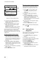
4.6
Replacing Route
Waypoints
Route waypoints are mutually replaced when
the navigators are sharing data.
1) Press WPT RTE and 5 to display the
route list.
2) Press
or
to select route.
3) Press
to display route editing screen.
4) On the route editing screen, place the
cursor on waypoint number to replace.
5) Enter new waypoint number.
6) Press the NU/CU ENT key. The message
shown in Figure 4-16 appears.
This waypoint already exists
Are you sure to change ?
ENT: Yes
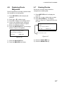
4.7
Erasing Routes
Routes are mutually erased when the
navigators are sharing data.
1) Press WPT RTE and 5 to display the
route list.
2) Press
or
to select route to erase.
3) Press the CLEAR key. The display
shown in Figure 4-17 appears if the route
is in use.
1st line
Are you sure to erase ?
ENT: Yes
MENU: No
This route is in use
MENU: No
Figure 4-16
7) Press the NU/CU ENT key.
8) Press the MENU ESC key twice.
Figure 4-17
4) Press the NU/CU ENT key.
5) Press the MENU ESC key.
4-7
4. NAVIGATION PLANNING
This page is intentionally left blank.
4-8
5. SETTING DESTINATION
5.1
Setting Destination
There are four ways by which you can set
destination:
• By cursor
• By MOB position or event position
• By waypoint, and
• By route.
The same destination is set on both
navigators when they are sharing data.
Setting single destination
1) Press the GOTO key. The menu shown in
Figure 5-2 appears.
GOTO Setting
1. Cursor
2. MOB/Event Position
3. Waypoint List
4. Route List
5. Cancel
: Cursor
Note: Previous destination is cancelled
whenever a destination is set.
Setting destination by cursor
Using the cursor you may set a destination
consisting of 30 points. When all 30 points
are entered, the GP-150-DUAL automatically
disables further entry.
ENT
: Enter
MENU : Escape
Figure 5-2 GOTO setting menu
2) Press 1 to select Cursor. The display
shown in Figure 5-3 appears.
Place cursor on desired location
Press ENT twice to finish
ENT:Enter CLR:Clear MENU:Escape
Figure 5-3
If the display in use is other than Plotter 1, the
Plotter 2 display is automatically selected.
3) Place the cursor on the location desired
for destination.
4) Press the NU/CU ENT key.
Note: To clear selection, press the
CLEAR key.
5) Press the NU/CU ENT key to finish.
Control is returned to the display mode in use
before you set destination. A dashed line
connects own ship and the destination, which
is marked with a flag, as shown in Figure 5-4.
5-1
5. SETTING DESTINATION
Flag
mark
Overwriting ?
ENT:Yes
MENU:No
Figure 5-6
Figure 5-4 Single destination set by cursor
Setting multiple destinations
1) Press GOTO and 1.
2) Place the cursor on the location desired
for a waypoint.
3) Press the NU/CU ENT key.
4) Repeat steps 2 and 3 to enter other points.
Waypoints are connected with a line.
5) Press the NU/CU ENT key to finish. The
route number entry display appears as
shown in Figure 5-5. If no route number
appears or you want to change the route
number shown, go to step 6 to enter route
number. To register the route under the
number shown, go to step 8.
Note: For the simple route, press the CLEAR
key and then go to step 8. The simple
route is not registered in the route list.
8) Press the NU/CU ENT key.
The waypoints do not have waypoint numbers,
however you can attach waypoint numbers by
doing the following.
1
Press WPT RTE and 5 to display the route
list.
2
Press
or
entered.
3
Press
4
Enter waypoint number, in three digits.
5
Press . If the waypoint number already
exists the message shown in Figure 5-7
appears.
to select route number
.
This waypoint already exists
Are you sure to change ?
ENT:Yes MENU:No
Figure 5-7
6
Enter route number
Press the NU/CU ENT key. The waypoint
entered here replaces previously entered
waypoint.
Note: To cancel replacement of
waypoint, press the MENU ESC
key at step 6 .
01
ENT:Enter MENU: Escape
Figure 5-5
7
Repeat steps 4 and 5 to enter other
waypoint numbers.
6) Key in route number.
7) Press the NU/CU ENT key. Waypoints are
marked with flags and are connected with
a dashed line.
8
Press the MENU ESC key twice to finish.
If the route number entered already exists the
message shown in Figure 5-6 appears.
5-2
When destination is cancelled, dashed lines
are erased but flags remain on the screen.
5. SETTING DESTINATION
Setting destination by MOB position or
event position
Setting destination through waypoint
list
Note: This operation cannot be performed
when there is no MOB position or
event position. The buzzer sounds and
the message shown in Figure 5-8
appears to alert you when there is no
MOB position or event position.
Note: A waypoint must exist to set it as
destination. When a waypoint does not
exist, the buzzer sounds and the
message shown in Figure 5-10
appears.
No waypoint data
No MOB/event data in memory
Figure 5-10
Figure 5-8
1) Press the GOTO key.
2) Press 2 to select MOB/Event Position.
The display shown in Figure 5-9 appears.
[MOB] Displaying MOB data
34° 12.345’ N 130° 23.456’ E
AUG 12’ 94 19 : 25U
[#01] Displaying event data
:Recall
34° 12.345’
N 130° 23.456’ E
ENT:Enter
AUG
12’ 03 19 : 25U
MENU:Escape
: Paging
ENT: Enter
MENU: Escape
Destination waypoint can be set through the
waypoint list two ways:
• By entering waypoint number, and
• By selecting waypoint by cursor
1) Press the GOTO key.
2) Press 3 to display the Waypoint List.
GOTO (Waypoint List)
Waypoint
Waypoint No.
No.
001 34° 12.345’ N 132° 23.456’ E
MARINE POINT AUG 12’ 03 12:35U
002
Figure 5-9
34° 12.345’ N 133° 12.345’ E
A POINT
AUG 13’ 03 13:28U
005 41° 34.567’ N 135° 23.456’ E
or
to select MOB position or
3) Press
event position. The MOB position appears
first. To select event position, press . If
selected position is within the current
display range, the cursor marks the
position. (The cursor does not appear on
the Highway, Navigation and Data
displays.)
4) Press the NU/CU ENT key. A flag appears
at position selected if it is within the
current display range. A dashed line
connects between own ship and MOB
position or event position.
When destination is cancelled, dashed lines
are erased but flags remain on the screen.
B POINT
No
.
List
AUG 14’ 03 09:45U
ENT:Enter
Waypoint number can be entered here
when this line appears in reverse video.
Figure 5-11 Waypoint list
Set destination by following 1 or 2 below.
1 Setting destination by waypoint no.
3) Enter waypoint number, in three digits.
You can clear entry by pressing the
CLEAR key.
4) Press the NU/CU ENT key.
Own ship position becomes starting point and
a dashed line runs between it and the
waypoint selected.
5-3
5. SETTING DESTINATION
2 Setting destination by selecting wpt.
. Each press of the key
3) Press
alternately enables manual entry of
waypoint number and selection of
waypoint number by cursor (through the
waypoint window).
4) Press
or
to select waypoint.
5) Press the NU/CU ENT key.
Own ship position becomes starting point and
a dashed line runs between it and the
waypoint selected.
Setting route as destination
Note: Route entered must exist to set it as
destination. The buzzer sounds and
the message shown in Figure 5-12
appears if you set enter a route which
does not exist.
No route data
Figure 5-12
A route to set as destination may selected
through the route list two ways:
• By entering route number, and
• By selecting route.
1) Press the GOTO key.
2) Press 4 to display the Route List. Then,
follow 1 or 2 in the adjacent column.
Route number can be entered here
when this line appears in reverse video.
GOTO (Route List)
FORWARD
Route No.
No. PTS
TOTAL
TTG
01
30
1234. 56nm
12D15H28M
02
25
234. 56nm
2D08H35M
05
8
57. 89nm
0D10H28M
06
30
*999. 99nm *9D23H59M
10
30
6543. 21nm
: No.
34D23H45M
List
ENT:Enter
MENU:Escape
Figure 5-13 Route list
1 By entering route number
3) Press
or
to select direction which to
traverse the route waypoints; forward or
reverse.
4) Enter route number.
5) Press the NU/CU ENT key.
Current position becomes starting point. A
solid line connects between the starting point
and first route waypoint and a dashed line
connects all other route waypoints.
2 By selecting a route
. Each press of the key
3) Press
alternately enables manual entry of route
number and selection of route number
(through the route window)
4) Press
or
to select route.
5) Press
or
to select direction in which
to traverse the route waypoints; forward
or reverse.
6) Press the NU/CU ENT key.
Current position becomes starting point. A
solid line connects between the starting point
and first route waypoint and a dashed line
connects all other route waypoints.
5-4
5. SETTING DESTINATION
Skipping route waypoints
You may skip route waypoints by displaying
"DI" (DIsable) next to the route waypoint in
the route list. Using Figure 5-14 as an
example, your ship is currently heading
toward waypoint 04 but is to switch course
and head to waypoint 03. In this case you
would want to skip waypoint 04.
Waypoint 01
Waypoint 02
Port A
Waypoint 03
Waypoint 04
New course
Waypoint 05
Waypoint 06
Port B
Figure 5-14
1) Press WPT RTE and 5 to display the
route list. Press the cursor keys to select
route.
"EN" indicates waypoint
is enabled. Display "DI"
to skip waypoint.
ROUTE
skip Distance
TTG
001 Speed Auto Man (012.0kt)
Trial
01 00 04 EN
nm
D H M
02 0 03 EN 345.67nm
2D 12H 34M
004
34° 12.345’ N 130° 23.456’ E
MARINE POINT AUG 10’ 03 12:35U
003
36° 12.345’ N 135° 23.456’ E
A POINT
AUG 10’ 03 13:45U
ENT:Enter
To reselect the waypoint, select it on the
to change "DI" to
route list and press
"EN".
Route waypoints are mutually skipped when
the navigators are sharing data.
5.2
Cancelling Destination
Destination is cancelled at both GPS
navigators when they are sharing data.
1) Press the GOTO key.
2) Press 5 to select Cancel. The message
shown in Figure 5-16 appears.
Release GOTO ?
ENT:Yes
MENU:No
(In Use, REVERSE)
:01
: RTE
2) Press
or
to select route waypoint
to skip.
3) Press
or
to shift the cursor to the
right of the waypoint number.
to change "EN"(ENable) to
4) Press
"DI"(DIsable).
5) Press the NU/CU ENT key.
WPT
Figure 5-16
3) Press the NU/CU ENT key.
Note: If you are using the simple route, it will
be erased when the destination is
canceled.
CLEAR: Delete
MENU:Escape
Figure 5-15 Route list
5-5
5. SETTING DESTINATION
5.3
Erasing Route
Waypoints (flags)
Flags are erased at both GPS navigators
when they are sharing data.
1) Place the cursor on the flag to erase.
2) Press the CLEAR key. The message
shown in Figure 5-17 appears if the
waypoint is currently selected as
destination, is part of a registered route,
or is part of the route currently being
navigated.
When flags are erased
When the origin waypoint is erased the
waypoint before it becomes the origin
waypoint. If there is no waypoint before the
origin waypoint, current position becomes the
origin waypoint.
Delete
Starting
point
Destination
waypoint
Course
Own
ship
1st line
Are you sure to erase ?
ENT:Yes MENU:No
This wpt is GOTO
This wpt is in registered route
This wpt is in selected route
Destination
waypoint
Figure 5-17
3) Press the NU/CU ENT key.
Figure 5-18 Route rearranged
Note: Flags can be erased collectively by
clearing the Plotter memory or both the
Plotter memory and GPS memory. See
page 9-1 for further details.
5-6
after erasing flag
When a destination is erased, the waypoint
which follows it becomes the destination. If
there is no waypoint after the destination
waypoint erased, route navigation is
cancelled.
5. SETTING DESTINATION
5.4
Finding Range and
Bearing Between Two
Points
Selecting course sailing method
The range and bearing to a destination can
be calculated two ways: Great Circle or
Rhumb Line. However, cross track error is
calculated in rhumb line only.
Great Circle: The great circle courseline is
the shortest course between two points on
the surface of the earth. (Imagine stretching a
piece of yarn between two points on the
earth.) However, this course requires
frequent change of heading to follow course
faithfully.
Rhumb Line: The rhumb line courseline is
the straight line drawn between two points on
a nautical chart. This course does not require
frequent changes of heading however it is not
the shortest since it follows the earth's
curvature.
1) Press MENU ESC, 9 and 1 to display the
PLOTTER SETUP menu.
PLOTTER SETUP
Memory Apportion
Trk = 1000 / 2000Pt
Bearing Ref.
True
Mag Variation
Auto
(07° W)
Calculation
R.L
User defined #1
Man
(00° E)
G.C
User defined #2
SOG
COG
User defined #3
RNG
User defined #4
BRG
ENT:Enter
Mag
MENU:Escape
Figure 5-20 PLOTTER SETUP menu
or
to selection Calculation.
2) Press
3) Press
or
to select R.L (Rhumb
Line) or G.C (Great Circle).
4) Press the NU/CU ENT key.
5) Press the MENU ESC key.
Calculation procedure
You can find the range and bearing between
two points by two waypoints or two latitude
and longitude positions.
1) Press MENU ESC and 5. The MANUAL
CALCULATION menu appears.
MANUAL CALCULATION
From
Waypoint No.
° .
’N
° .
’E
To
Waypoint No.
° .
’N
° .
’E
Trial speed : Auto
Man
(
. kt)
Rng:
.
m
Brg:
. °
TTG:
D H M
: Cursor MENU : Escape
ENT : Calculation
: N/S, E/W
Figure 5-19 MANUAL
CALCULATION menu
2) Choose two points by one of the methods
below.
Latitude and longitude positions
1) Press
.
to switch from
2) If necessary press
North latitude and to South latitude vice
versa.
3) Key in latitude.
to switch from West
4) If necessary press
longitude to East longitude and vice versa.
5) Key in longitude.
6) Press
.
7) Repeat 2-5 to enter other point.
Waypoints
1) Key in first waypoint number (000-999).
(000 is reserved for own ship position.)
2) Press
twice.
3) Key in other waypoint number (000-999).
4) Press
to shift the cursor to the Trial
Speed line.
5) Press
or
to select Auto or Man. Auto
5-7
5. SETTING DESTINATION
uses ship's average speed to calculate
time-to-go.
6) If you selected Man, enter speed.
7) Press the NU/CU ENT key.
The range, bearing and time-to-go between
two points appear on the display. If data
entered is wrong or insufficient the buzzer
sounds and the message "INCOMPLETE
DATA" appears. If the data contains error,
"*" and all nines appear as the calculation
results.
8) Press the MENU ESC key.
5-8
6. SETTING UP VARIOUS DISPLAYS
6.1
The Data Display
• Trip elapsed time (TRIP TM)
The user may select what data to display in
four locations on the data display.
D3D
SAFE
JAN 12, 2005 23:59’59" U
POSITION
WGS84
100m
12 23.456’ N
123 23.456’ E
RNG
TO : 001
BRG
SOG
12.3
MARINE
POINT1
223.4
31.23 nm
NEXT
COG
kt
123.4
: 002
MARINE
POINT2
User-defined
User-defined
display data #1 display data #4
User-defined
display data #2
User-defined
display data #3
User-defined
display window
Figure 6-1 Data display
The data the user may display are;
• Altitude (ALT)*
• Average course (AVR COG)
• Water temperature (W.TMP)#, and
• Velocity to destination (VTD)*
• ETA to route
*ALT: Displayed only in 3D position fixing.
*RT. DIST: Total distance from current
position to ultimate destination. Appears
when following a registered route or a
cursor-created route.
*VTD: When following a route, plus or minus
appears next to indication to denote which
direction the route is being traversed.
# Requires external sensor.
1) Press MENU ESC, 9 and 1 to display the
PLOTTER SETUP menu.
PLOTTER SETUP
Trk = 1000 / 2000Pt
Memory Apportion
Bearing Ref.
True
Mag Variation
Auto
(07° W)
Calculation
Mag
Man
(00° E)
R.L
• Average speed (AVR SPD)
User defined #1
SOG
• Course (COG)
User defined #2
COG
User defined #3
RNG
• Course error (dCOG)
User defined #4
BRG
ENT:Enter
MENU:Escape
• Cross track error (XTE)
• Depth (W.DPT)#
• ETA to waypoint (ETA)
• Range to waypoint (RNG)
• Bering to waypoint (BRG)
• Route time-to-go (RT.TTG)
• Speed (SOG)
• Time-to-go to waypoint (TTG)
• Total route distance (RT.DIST)*
G.C
Figure 6-2 PLOTTER SETUP menu
2) Press
or
to select one of four of
"User defined" (#1, #2, #3, #4).
3) Press
or
to select data to display.
4) Press the NU/CU ENT key. To select the
data to display at other user defined
displays, repeat steps 2 and 3.
5) Press the MENU ESC key.
• Trip distance (TRIP)
6-1
6. SETTING UP VARIOUS DISPLAYS
6.2
Position Format
Position can be displayed in latitude and
longitude, Loran C LOPs, or Decca LOPs,
and the default format is latitude and
longitude.
Displaying position in latitude and
longitude
1) Press MENU ESC, 9 and 8 to display the
LOP SETUP menu.
LOP SETUP
Lat / Long
Pos Display
LOP
LOP Display
LC
DE
LC Chain
7980 : 23-43
∆LOP
-12.3us +0.34 us
DE Chain
24:G - P
∆LOP
+0.80 Lane -1.00 Lane
(RED:1 GREEN:2 PURPLE:3)
: Select
MENU : Escape
ENT : Enter
: +/-
Figure 6-3 LOP SETUP menu
2)
3)
4)
5)
Press
to select Pos Display.
Press
to select Lat/Long.
Press the NU/CU ENT key.
Press the MENU ESC key.
Displaying position in LOPs
Press MENU ESC, 9 and 8.
Press
to select Pos Display.
Press to select LOP.
Press
to select LOP Display.
Press
or
to select LC (Loran C) or
DE (Decca).
Follow 1 or 2 in the adjacent column
according to selection in step 5.
1)
2)
3)
4)
5)
6-2
1 For Loran LOPs
6) Press
to select LC Chain.
7) Key in GRI code referring to the Loran C
chain list in the Appendix. If the GRI code
is 9970, for example, press 9, 9, 7, 0.
8) Key in secondary code pair referring to
the Loran C chain list in the Appendix.
9) If necessary press
to choose ∆LOP to
enter correction value. Key in correction
to switch from plus to
value. Use
minus or vice versa.
10) Press the NU/CU ENT key.
11) Press the MENU ESC key.
2 For Decca LOPs
6) Press
to select DE Chain.
7) Key in Decca chain number referring to
the Decca chain list in the Appendix. For
the Europe chain, for example, press 0, 1.
8) Key in Decca lane pair. Red, 1; Green 2,
and Purple 3.
9) If necessary press
to choose
LOP
to enter correction value. Key in
to switch from
correction value. Use
plus to minus or vice versa.
10) Press the NU/CU ENT key.
11) Press the MENU ESC key.
6. SETTING UP VARIOUS DISPLAYS
Entering waypoints using LOPs
1) Press WPT RTE and 4.
to display LOPs.
2) Press
WAYPOINT LIST (LOP, LC)
001 36365.2
59102.3
MARINE POINT AUG12’ 03 12 : 35U
002 36512.3
___ A POINT
59134.5
AUG13’ 03 13 : 45U
003 _ _ _ _ _ , _
_____,_
___ _ _ _ _ _ _ _ _ _ _ _ _
004 _ _ _ _ _ , _
_____,_
___ _ _ _ _ _ _ _ _ _ _ _ _
: L/L
LOP
ENT : Enter
: Edit
MENU : Escape
Figure 6-4 LOP display on the waypoint list
5) Key in LOP1 and LOP2, to enable
calculation.
6) Press
to calculate LOPs. "Calculating"
appears between parentheses during the
calculation. Actual LOPs replace
"Calculating" upon completion of the
calculation.
If the conversion fails, the message "Failed in
Conversion" appears for three seconds.
Press the CLEAR key and reenter the right
LOP1 and LOP2.
7) Press
or
to select mark.
8) Press the NU/CU ENT key.
9) Enter comment, if desired.
10) Press the NU/CU ENT key twice.
The waypoint list appears.
3) Press
or
to select waypoint
number.
4) Press
or . Your display should look
like one of the displays in Figure 6-5.
Edit=Waypoint : 001
LC8930 :
30
50
58654.3
33 8931.2
(34° 12.345’ N 130° 23.456’ E)
Mark :
Cmnt : MARINE POINT
: Cursor
ENT : Enter
: Column
MENU : Escape
Loran C LOP input screen
Edit=Waypoint : 001
DE : 32 (9C) RED
GREEN
11 A:12.23
2H:24.35
(34° 12.345’ N 130° 23.456’ E)
Mark :
Cmnt : MARINE POINT
ABCDEFGHIJ fi 1, 2 ~ 9, 0
: Cursor
: Column
ENT : Enter
MENU : Escape
Decca LOP input screen
Figure 6-5 LOP input screens
6-3
6. SETTING UP VARIOUS DISPLAYS
6.3
Demo Display
The demo display provides simulated
operation of this unit. Own ship tracks, at the
speed selected, a figure eight course, starting
from position entered. All controls are
operative; you may change course, enter
marks, etc.
1) While pressing and holding down NU/CU
ENT, turn on the power.
DEMO SETTING
BASE POSITION
_ _° _ _._ _ _’ N _ _ _°_ _._ _ _’ W
SPEED
00.00kt
: Cursor
ENT: Enter
: Column
: N/S, E/W
Figure 6-6 DEMO SETTING menu
2) Key in latitude of initial position.
to switch from
3) If necessary, press
north latitude to south latitude or vice
versa.
4) Key in longitude.
to switch from
5) If necessary, press
east longitude to west longitude or vice
versa.
6) Press .
7) Key in speed.
8) Press the NU/CU ENT key to start the
demonstration mode. The plotter display
appears and the demo mode begins. After
the test results appear, the demo setting
mode menu appears.
9) To quit the demo display, turn off the
power.
All tracks, marks and data entered during the
simulation are erased and default demo
mode settings are restored.
6-4
Note: The return to the normal mode, turn off
the power and then turn it on while
pressing and hold down NU/CU ENT
key.
7. ALARMS
7.1
Overview
7.2
Arrival Alarm, Anchor
Watch Alarm
There are seven alarm conditions which
generate both aural and visual alarms.
Arrival alarm
When an alarm setting is violated, the buzzer
sounds and the name of the alarm being
violated appears on the display. The alarm
icon also appears on the Plotter 1, Plotter 2
and Highway displays. This occurs on both
navigators when they are sharing data.
The arrival alarm informs you that own ship
is approaching a destination waypoint. The
area that defines an arrival zone is that of a
circle which you approach from the outside
of the circle. The alarm will be released if
own ship enters the circle.
Alarm status is output to external equipment
through the DATA1 port and the DATA4 port
when it outputs data in NMEA format.
34° 23.456´ N 135° 45.678´ E D3D 100m
Alarm
setting
Own ship’s
position
Destination
waypoint
: Alarm range
SAFE
Figure 7-2 How the arrival alarm works
BRG
Alarm message
234°
COG
345°
Alarm
icon
Arrival alarm
Speed alarm
Press CLEAR to silence beep
RNG
1) Press the MENU ESC key.
2) Press 4 to display the ALARM
SETTINGS menu.
123 nm
ALARM SETTINGS
SOG
Arrival/Anchor
Alarm Range
XTE
Alarm Range
Ship Speed
Speed Range
Next Page
12.3
Press
CLEAR
Press CLEAR to silence beep and close window
ENT : Enter
Select OFF instead of alarm name on the
appropriate menu. This disables the alarm
on both navigators when they are sharing
data.
MENU : Escape
Figure 7-3 ALARM SETTINGS
menu, page 1/2
Clearing the aural and visual alarms
Disabling an alarm
Arr.
Anc.
Off
0.100nm
On
Off
0.050nm
Over
In
Over Off
000.0 ~ 025.0kt
: Select
Figure 7-1 Location of alarm
messages and alarm icon
Press the CLEAR key. When the navigators
are sharing data, the "reset alarm signal" is
transmitted to the other navigator to clear
aural and visual alarms there.
1/2
3)
4)
5)
6)
7)
8)
Press
to select Arrival/Anchor.
Press
or
to select Arr.
Press
to select Alarm Range.
Key in alarm range (0.001-9.999 nm).
Press the NU/CU ENT key.
Press the MENU ESC key.
When own ship nears a waypoint by the
range set here, the buzzer sounds and the
message "Arrival alarm" appears.
7-1
7. ALARMS
7.3
Anchor watch alarm
The anchor watch alarm sounds to warn you
that own ship is moving when it should be at
rest.
Alarm
setting
Own ship’s
position
: Alarm range
Cross Track Error (XTE)
Alarm
The XTE alarm warns you when own ship is
off its intended course.
Starting
waypoint
Own ship’s
position
Alarm
setting
Destination
waypoint
Destination
waypoint
: Alarm range
Figure 7-5 How the XTE alarm works
Figure 7-4 How the anchor
watch alarm works
Before setting the anchor watch alarm, set
present position as destination waypoint,
referring to chapter 5.
1)
2)
3)
4)
5)
6)
7)
Press MENU ESC and 4.
Press
to select Arrival/Anchor.
Press
or
to select Anc.
Press
to select Alarm Range.
Key in alarm range (0.001-9.999 nm).
Press the NU/CU ENT key.
Press the MENU ESC key.
When own ship drifts by the range set here,
the buzzer sounds and the message "Anchor
alarm" appears.
7-2
1)
2)
3)
4)
5)
6)
7)
Press MENU ESC and 4.
Press
or
to select XTE.
Press
or
to select On.
Press
to select Alarm Range.
Key in alarm range (0.001-9.999 nm).
Press the NU/CU ENT key.
Press the MENU ESC key.
When own ship strays from the intended
track by the range set here, the buzzer
sounds and the message "Cross track error
alarm" appears.
7. ALARMS
7.4
Speed Alarm
The speed alarm sounds when ship's speed
is lower or higher (or within) the alarm range
set.
1) Press MENU ESC and 4.
2) Press
or
to select Ship Speed.
3) Press
or
to select In or Over.
In: Alarm sounds when speed is within range
set.
Over: Alarm sounds when speed is higher or
lower than range set.
4)
5)
6)
7)
8)
Press
to select Speed Range.
Key in low speed.
Key in high speed.
Press the NU/CU ENT key.
Press the MENU ESC key.
When speed is higher or lower (or within)
than the speed set here, the buzzer sounds
and the message "Speed alarm" appears.
7.5
Trip Alarm
The trip alarm sounds when the distance run
is greater than the trip alarm setting.
1) Press MENU ESC and 4.
2) Press
to select Next Page. The menu
shown in Figure 7-6 appears.
ALARM SETTINGS
To Previous Page
Trip (CLR:Reset)
Trip Range
Water Temp.
Temp. Range
Depth
Depth Range
WAAS/DGPS
: Select
MENU : Escape
2/2
Off
On
Off
0123.00nm
In
Over Off
+12.0 ~ +15.0°C
In
Over Off
0003.0 ~ 0200.0ft
Off
On
ENT : Enter
: +/-
Figure 7-6 Alarm settings menu, page 2/2
3) Press
or
to select Trip.
4) If necessary, press CLEAR to reset the
trip distance and trip elapsed time.
5) Press
or
to select On.
6) Press
to select Trip Range.
7) Key in trip range.
8) Press the NU/CU ENT key.
9) Press the MENU ESC key.
When the ship's distance run is higher than
the trip range set here, the buzzer sounds
and the message "Trip alarm" appears.
7-3
7. ALARMS
7.6
Water Temperature
Alarm
The water temperature alarm sounds when
the water temperature is higher or lower (or
within) the preset temperature. This alarm
requires a water temperature signal from
external equipment.
1) Press MENU ESC and 4.
2) On page 2/2 of the ALARM SETTINGS
menu, press
or
to select Water
Temp.
3) Press
or
to select In or Over.
4) Press
to select Temp. Range.
5) Key in low temperature.
6) Key in high temperature.
7) Press the NU/CU ENT key.
8) Press the MENU ESC key.
When the water temperature is higher or
lower (or within) the preset value, the buzzer
sounds and the message "Water temp
alarm" appears.
7.7
Depth Alarm
The depth temperature alarm sounds when
the depth is higher or lower (or within) the
preset depth. This alarm requires video
sounder connection.
1) Press MENU ESC and 4.
2) On page 2/2 of the ALARM SETTINGS
menu, press
or
to select Depth.
3) Press
or
to select In or Over.
4) Press
to select Depth Range.
5) Key in low depth.
6) Key in high depth.
7) Press the NU/CU ENT key.
8) Press the MENU ESC key.
When the depth is higher or lower (or within)
the preset value, the buzzer sounds and the
message "Depth alarm" appears.
7.8
WAAS/DGPS Alarm
The WAAS/DGPS alarm sounds when the
WAAS/DGPS signal is lost. This alarm may
be enabled or disabled as below.
1) Press MENU ESC and 4.
2) On page 2/2 of the ALARM SETTINGS
menu, press
or
to select
WAAS/DGPS.
3) Press
to select On, or
to select off.
4) Press the NU/CU/ENT key.
5) Press the MENU ESC key.
7-4
8. MENU SETTINGS
8.1
GPS SETUP Menu
Menu description
Fix mode
Two position fixing modes are available: 2D
and 2/3D. The 2D mode provides two
dimensional position fixes (latitude and
longitude only) and is used when three
satellites are in line of sight of the GPS
receiver. The 2/3D mode switches between
two and three dimension position fixing
automatically depending on how many
satellites (three or four) are in line of sight of
the GPS receiver.
ANT Height
Enter the height of the antenna unit above
sea surface (000-999 ft, 000-304 m). The
default setting is 16 ft.
GPS smoothing, speed
During position fixing, ship’s velocity (speed
and course) is directly measured by
receiving GPS satellite signals. The raw
velocity data may change randomly
depending on receiving conditions and other
factors. You can reduce this random
variation by increasing the smoothing. Like
with latitude and longitude smoothing, the
higher the speed and course smoothing the
more smoothed the raw data. If the setting is
too high, however, the response to speed
and course change slows. For no smoothing,
enter "0." "5" is suitable for most conditions.
Speed average
Calculation of ETA and TTG, etc. is based on
average ship’s speed over a given period.
The default setting is one minute. Change
the setting if the ETA seems wrong.
RAIM function/RAIM accuracy
GPS smoothing, position
RAIM (Receiver Autonomous Integrity
Monitoring) is a diagnostic function which
tests the accuracy of the GPS signal. To use
the RAIM function, enter the range (from
own ship in meters) for which you want to
know position confidence, on the GPS Setup
2/2 menu. The receiver estimates position
confidence using range value and detected
satellite error, and displays (provided the
RAIM function is active) the results as
one of three levels of position confidence, at
the top right-hand corner of the screen. The
three levels are as follows:
When the DOP or receiving condition is
unfavorable, the GPS fix may change greatly,
even if the vessel is dead in water. This
change can be reduced by smoothing the
raw GPS fixes. A setting between 0 and 9 is
available. The higher the setting the more
smoothed the raw data, however too high a
setting slows response time to change in
latitude and longitude. This is especially
noticeable at high ship’s speeds. "0" is the
normal setting; increase the setting if the
GPS fix changes greatly.
SAFE: GPS signal is normal. The positioning
accuracy satisfies the setting value.
CAUTION: RAIM accuracy cannot be
calculated. (Signals from more than five GPS
satellites are necessary.) The positioning
accuracy does not satisfy the setting value.
UNSAFE: GPS signal is abnormal, therefore
the positioning accuracy is not reliable. Note
that the GP-150-DUAL does not exclude
abnormal signals automatically.
Disable satellite
Every GPS satellite is broadcasting
abnormal satellite number(s) in the Almanac.
Using this information, the GPS receiver
automatically eliminates any malfunctioning
satellite from the GPS satellite schedule.
However, the Almanac sometimes may not
contain this information. You can disable an
inoperative satellite manually on the GPS
SETUP menu.
8-1
8. MENU SETTINGS
SAFE: GPS signal is safe to use.
CAUTION: RAIM accuracy is shorter than
protected level or RAIM measurement not
possible.
UNSAFE: GPS signal is not safe to use.
Setting up the GPS SETUP menu
Fix mode
1) Press MENU ESC, 9 and 6 to display the
GPS SETUP menu.
GPS SETUP
Enter the range for which you want to know
position confidence
Geodetic datum
Select the geodetic chart system you are
using. WGS-84 (standard GPS chart system)
and NAD 27 can be directly selected. For
other charts, select "OTHER" and enter chart
number referring to the geodetic chart list in
the Appendix.
To output position data to ECDIS (Electronic
Chart Display and Information System), turn
on the power while holding down the 0 key to
disable access to the Geodetic Datum menu.
Then, "Cannot be changed" is shown in the
Geodetic Datum menu as in Figure 8-2 on
the next page. To stop outputting position
data to ECDIS, turn on the power while
holding down the 0 key.
Position offset
You may apply an offset to position
generated by the internal GPS receiver, to
compensate for difference between GPS
position and chart position.
Time difference
The GPS system uses UTC time. If you
would rather use local time, enter the
difference in hours between local time and
UTC. Use the + and - keys for times later or
earlier than UTC, respectively.
Position
When executing cold start there is no
satellite information in the unit’s memory,
thus it may take some time to find position.
To fix position faster, enter estimated
position.
8-2
Fix Mode
ANT Height
Disable Satellite
GPS Smoothing
Posn
Spd
Speed Average
To Next Page
1/2
2D
2/3D
016 ft
(1-32)
12
0 0 0 0 (0000-9999 sec)
0 0 0 5 (0000-9999 sec)
0 0 6 0 (0000-9999 sec)
: Select
MENU : Escape
ENT : Enter
Figure 8-1 GPS SETUP menu, page 1/2
2) Press
to select Fix Mode.
3) Press
or
to select fix mode
desired.
4) Press
to change other settings, or
press MENU ESC to register settings and
escape.
Disabling satellites
When the navigators are sharing data,
satellites are disabled on both navigators.
1) Press MENU ESC, 9 and 6.
2) Press
or
to select Disable
satellite.
3) Key in satellite number, in two digits
(01-32). Three sets of satellite numbers
may be entered.
4) Press the NU/CU ENT key. If an invalid
number is entered the buzzer sounds.
5) Press the MENU ESC key.
Note: To enable all disabled satellites, press
the CLEAR key at step 3. All satellite
numbers on the Disable satellite line
are erased.
8. MENU SETTINGS
GPS position smoothing
RAIM accuracy
1) Press MENU ESC, 9 and 6.
2) Press
or
to select Posn.
3) Enter smoothing factor in three digits
(0000-9999).
4) Press the NU/CU ENT key.
5) Press the MENU ESC key.
1) Press MENU ESC, 9 and 6.
2) Press
or
to select RAIM accuracy
on page 2/2.
3) Key in the range for which you want to
know RAIM accuracy (1 to 999 m).
GPS speed smoothing
1) Press MENU ESC, 9 and 6.
2) Press
or
to select Spd.
3) Enter smoothing factor in three digits
(0000-9999).
4) Press the NU/CU ENT key.
5) Press the MENU ESC key.
Speed averaging
1) Press MENU ESC, 9 and 6.
2) Press
to select Speed Average.
3) Enter smoothing factor in two digits
(0000-9999).
4) Press the NU/CU ENT key.
5) Press the MENU ESC key.
RAIM function
1) Press MENU ESC, 9 and 6.
2) Press
to select RAIM function on
page 2/2.
GPS SETUP
2/2
To Previous Page
RAIM Function
OFF
ON
RAIM Accuracy 100 m
Geodetic Datum WGS84 NAD27 OTHER
(Cannot be changed)
(001)
Posn Offset
0.000’ N 0.000’ E
Time Diff.
+00:00
Posn
38 00.000’ N 123 00.000’ W
: Select
MENU : Escape
ENT : Enter
: +/
Figure 8-2 GPS SETUP menu, page 2/2
or
3) Press
to turn RAIM function ON
or OFF as appropriate.
4) Press the NU/CU ENT key.
5) Press the MENU ESC key.
Note: Unit is meter only.
4) Press the NU/CU ENT key.
5) Press the MENU ESC key.
Geodetic datum
1) Press MENU ESC, 9 and 6.
2) Press
or
to select Geodetic
Datum on page 2/2.
3) Press
or
to select geodetic datum
to use. For geodetic datum other than
WGS-84 or NAD-27, select OTHER and
key in chart number (001-173) referring
to the geodetic chart list in the Appendix.
4) Press the NU/CU ENT key.
5) Press the MENU ESC key.
Position offset
If you do not know the type of chart you are
using, GPS position may be wrong. Note the
difference in position when moored to a pier
and enter it on the GPS SETUP menu, to get
correct position.
1) Press MENU ESC, 9 and 6.
2) Press
or
to select Posn Offset on
page 2/2.
to switch from
3) If necessary press
north latitude to south latitude or vice
versa.
4) Key in latitude correction.
to switch from
5) If necessary press
east longitude to west longitude or vice
versa.
6) Key in longitude correction.
7) Press the NU/CU ENT key.
8) Press the MENU ESC key.
L
The L icon appears when L/L offset is
applied.
8-3
8. MENU SETTINGS
Time difference
1) Press MENU ESC, 9 and 6.
2) Press
or
to select Time Diff on
page 2/2.
3) Key in time difference (-14:00 to +14:00).
to change from plus to minus
4) Press
or vice versa.
5) Press the MENU ESC key.
Position
After the unit is installed you may enter
position to shorten the time it takes to find
position. (It takes about two minutes when
there is no position data entered.)
1) Press MENU ESC, 9 and 6.
2) Press
or
to select Posn on page
2/2.
to switch from
3) If necessary, press
north latitude to south latitude or vice
versa. Key in latitude.
to switch from
4) If necessary, press
east longitude to west longitude or vice
versa. Key in longitude.
5) Press the NU/CU ENT key.
6) Press the MENU ESC key.
8.2
Units of Measurement
Unit of distance
Distance can be displayed in nautical mile,
kilometer or statute mile as follows.
1) Press MENU ESC, 9 and 2. The UNIT
SETUP menu appears.
UNIT SETUP
Unit of Distance
nm
km
sm
Unit of Depth
Unit of Temp.
m
°C
ft
°F
FA
Unit of Altitude
m
ft
:Select
ENT : Enter
MENU : Escape
Figure 8-3 UNIT SETUP menu
8-4
2) Press
to select Unit of Distance.
3) Press
or
to select unit; nm, km or
sm.
4) Press the NU/CU ENT key.
5) Press the MENU ESC key.
Unit of depth
1) Press MENU ESC, 9 and 2.
2) Press
or
to select Unit of Depth.
3) Press
or
to select unit; meter, feet,
or fathom.
4) Press the NU/CU ENT key.
5) Press the MENU ESC key.
Unit of water temperature
1) Press MENU ESC, 9 and 2.
2) Press
or
to select Unit of Temp.
3) Press
or
to select unit; Centigrade
or Fahrenheit.
4) Press NU/CU ENT and MENU ESC.
Unit of altitude
Available only in 3D mode.
1)
2)
3)
4)
5)
Press MENU ESC, 9 and 2.
Press
or
to select Unit of Altitude.
Press
or
to select unit.
Press the NU/CU ENT key.
Press the MENU ESC key.
8. MENU SETTINGS
8.3
Size and Brilliance of
Markers
The DISPLAY SETUP menu lets you select
the size and brilliance of various markers.
Waypoint mark size
The size of the waypoint mark can be
selected to large or small.
Large waypoint mark
No icon
Grid tone
The grid can be displayed in light or dark
tone, or turned off.
12
1) Press MENU ESC and 1. The DISPLAY
SETUP menu appears.
With icon
12
Small waypoint mark
DISPLAY SETUP
Grid
Course Bar
Time Mark
Waypoint Size
Cursor Size
Dark
Dark
Dark
Large
Large
Light
Light
Light
Small
Small
Off
Off
Off
: Select
ENT : Enter
MENU : Escape
Figure 8-4 DISPLAY SETUP menu
2) Press
to select Grid.
3) Press
or
to select brilliance.
4) Press NU/CU ENT and MENU ESC.
Figure 8-5 Waypoint mark size
1)
2)
3)
4)
Press MENU ESC and 1.
Press
or
to select Waypoint Size.
Press
or
to select Large or Small.
Press NU/CU ENT and MENU ESC.
Cursor size
The size of the cursor can be selected to
large or small.
Large cursor
Course bar tone
Small cursor
The course bar can be displayed in light or
dark tone, or turned off.
1)
2)
3)
4)
5)
Press MENU ESC and 1.
Press
or
to select Course Bar.
Press
or
to select brilliance.
Press the NU/CU ENT key.
Press the MENU ESC key.
Time mark tone
The time mark can be displayed in light or
dark tone, or turned off.
1)
2)
3)
4)
5)
Figure 8-6 Cursor size
1)
2)
3)
4)
5)
Press MENU ESC and 1.
Press
to select Cursor Size.
Press
or
to select Large or Small.
Press the NU/CU ENT key.
Press the MENU ESC key.
Press MENU ESC and 1.
Press
or
to select Time Mark.
Press
or
to select brilliance.
Press the NU/CU ENT key.
Press the MENU ESC key.
8-5
8. MENU SETTINGS
Enlarging characters
8.4
The size of the indications of position or
user-defined display areas can be enlarged
on the Data display.
Besides its fundamental function of
displaying position, the GP-150-DUAL can
also receive data and output data to external
equipment, through an interface unit. Before
outputting data to external equipment, first
determine what data the external equipment
requires. Output only necessary data to
ensure data will be output correctly.
1) On the Data display, with no enlarged
characters, press the CURSOR ON/OFF
key to turn on the zoom icon.
2) Operate the cursor keys to select data to
enlarge in the window.
3) Press the ZOOM IN key.
To switch character size from enlarged to
normal, press the ZOOM OUT key at step 3.
Position
D3D
SAFE
JAN 12, 2006 23:59'59" U
POSITION
WGS84
12° 23.456' N
123° 23.456' E
RNG
BRG
31.23 nm
SOG
12.3
100m
223.4°
COG
kt
123.4°
User-defined
display window
ZOOM
OUT
JAN 12, 2006 23:59'59" U
All data transmitted by marine electronics
equipment are prefixed with a two-character
code called a talker. The same talker must
be shared by the transmitting and receiving
equipment to transmit and receive data
successfully. The GP-150-DUAL transmits
data using the GP (GPS talker), LC (Loran)
or DE (Decca) talker.
DATA 1 output setting
TO : 001
MARINE
POINT1
NEXT
: 002
MARINE
POINT2
Zoom icon
ZOOM
IN
D3D
SAFE
N12°
Outputting Data
100m
POSITION
23.456'
E123°
23.456'
WGS84
1) Press MENU ESC, 9 and 3. The DATA 1,
3 OUTPUT SETUP menu appears.
DATA 1, 3 OUTPUT SETUP
Data Fmt.
Talker ID
V1.5
GP
V2.0 IEC
LC
DE
Output Data (00-90 sec) 91%
1. AAM:00 APA:00 APB:04 BOD:00
2. BWR:00 BWW:00 GGA:00
3. RMB:01 RMC:01 VTG:01
4. WNR:00 WPL:00 XTE:00
5. GNS:00 GBS:00 Rnn:00
DATA3. Log Pulse
200ppm
ENT : Enter
MENU : Escape
Settings shown here are default settings.
This line appears only when LOG is
selected by internal jumper wires.
Figure 8-8 DATA 1 OUTPUT
SETUP menu
Figure 8-7 How to enlarge
indications on the data display
8-6
GLL:00
WCV:00
ZDA:01
RTE:00
400ppm
8. MENU SETTINGS
2) Press
to select Data Fmt.
3) Press
or
to select NMEA 0183
(V1.5 or V2.0) or IEC 61162-1.
4) Press the NU/CU ENT key. Talker ID
appears in reverse video.
5) Press
or
to select GP, LC or DE.
6) Press the NU/CU ENT key.
7) Enter Tx interval for each output data
sentence in line 1. Tx interval is available
in 00, 01, 02, 03, 04, 05, 06, 10, 15, 20,
30, 60 and 90 (seconds).
8) Press the NU/CU ENT key.
9) Enter Tx interval for each output data
sentence in lines 2 through 5. Press the
NU/CU ENT key after setting each line.
For detailed information about Tx interval
see the chapter on installation. However, the
Tx interval settings entered by the installer of
the equipment should not be changed unless
absolutely necessary.
BWC and WNC are for great circle
navigation and BWR and WNR are for
rhumb line navigation. However, all output
data are calculated by rhumb line.
When the external equipment cannot display
data input from the GP-150-DUAL correctly,
the rate of operation should be lowered.
For example, set a rate of operation less
then 60% for the Temperature Indicator
TI-20.
1) Press MENU ESC, 9 and 3.
2) Press
to select DATA 3 or Log Pulse.
3) For log pulse, press
or
to select
log pulse of external equipment; 200 ppm
or 400 ppm.
4) Press the NU/CU ENT key twice.
Setting DATA 4 to data output
The DATA 4 port connects to a personal
computer, DGPS receiver or YEOMAN
equipment.
1) Press MENU ESC, 9 and 5. The DATA 4
I/O SETUP (1/2) menu appears.
DATA 4 I/O SETUP
DATA 4. Level
Data
To Next Page
ENT : Enter
RS232C
Out
1/2
RS422
Com. DGPS
: Select
MENU : Escape
Figure 8-9 DATA 4 I/O SETUP menu (1/2)
2) Press
to select Level.
3) Press
or
to select level of external
equipment; RS232C or RS422.
4) Press the NU/CU ENT key.
5) Press
or
to select Out.
6) Press
to select To Next Page. The
DATA 4 I/O SETUP (2/2) menu appears.
DATA 3 output setting
The DATA 3 connector can output IEC
61162-1/NMEA 0183 data or log pulse. For
NMEA 0183, IEC 61162-1 the same data
output by DATA 1 is output from DATA 3.
For log pulse, select 200 or 400 pulse per
second depending on the device connected.
8-7
8. MENU SETTINGS
DATA 4 I/O SETUP
<Out>
2/2
To Previous Page
Data Fmt.
V1.5 V2.0 IEC
Talker ID GP
LC
DE
Output Data
(00-90 sec)
100%
1. AAM:00 APA:00 APB:04 BOD:00
2. BWR:00 BWW:00 GGA:00 GLL:01
3. RMB:01 RMC:00 VTG:01 WCV:00
4. WNR:00 WPL:00 XTE:00 ZDA:01
5. GNS:00 GBS:01
ENT : Enter
Rnn:00
RTE:00
MENU : Escape
Figure 8-10 DATA 4 I/O SETUP menu (2/2)
7) Press
to select Baud Rate.
8) Press
or
to select baud rate; 4800
bps, 9600 bps, or 19200 bps.
9) Press the NU/CU ENT key.
10) Press
or
to select WPT/RTE.
11) Press
to select Command. Stop, on
the same line as Command, appears in
reverse video.
12) Press
to select Start. The message
shown in Figure 8-12 appears.
Loading erases current data
and stops Route navigation
Are you sure to load ?
ENT: Yes
7) Follow "DATA 1 output setting" from step
2.
8.5
Receiving Data from
Personal Computer
Waypoints and routes data can be
downloaded from a personal computer,
through the DATA 4 connector.
1) Press MENU ESC, 9 and 5.
2) Press
to select DATA 4 Level.
3) Press
or
to select level of personal
computer; RS232C or RS422.
4) Press the NU/CU ENT key.
5) Press
or
to select Com.
6) Press
to select To Next Page. The
DATA 4 I/O SETUP menu appears.
To Previous Page
Baud Rate
Now loading
MENU:Stop
Figure 8-13
14) Operate the computer to output data.
When data is loaded, the cursor shifts to
Stop.
15) Press the MENU ESC key. When data is
loaded successfully, The message shown
in Figure 8-14 appears.
Loading ended successfully
2/2
9600 bps
WPT/RTE WPT
Stop
Start
Save Data
Command
WPT/RTE
Stop
Start
: Select
MENU : Escape
Figure 8-11 DATA 4 I/O SETUP menu (2/2)
8-8
13) Press the NU/CU ENT key. The message
shown in Figure 8-13 appears.
Press any key
Load Data
Command
ENT : Enter
Figure 8-12
Waypoint/Route data !
Loading waypoint/route data
DATA 4 I/O SETUP <Com.>
MENU:No
Figure 8-14
If data could not be loaded, the message
shown in Figure 8-15 appears.
Failed in loading
Invalid data
Press any key
Figure 8-15
8. MENU SETTINGS
Stopping loading of data
1) Press the MENU ESC key. The message
shown in Figure 8-16 appears.
Waypoint area is full !
Can’t load any data
Press any key to stop
Are you sure to stop ?
Figure 8-19
ENT: Yes
MENU:No
Figure 8-16
2) To quit loading, press the NU/CU ENT
key. The cursor shifts to Stop.
3) To start loading, select Start.
4) Press the NU/CU ENT key.
Loading waypoint data from YEOMAN
equipment
1) Do steps 1 through 9 in "Loading
Waypoint/route data."
2) Press
or
to select WPT.
3) Press
to select Command.
4) Press
to select Start. The message
shown in Figure 8-17 appears.
7) When the data is loaded, press CU/NU
ENT and MENU ESC. The message
shown in Figure 8-20 appears.
The number of valid and invalid waypoints
appear in the message.
Loading completed
Valid waypoint : 0
Invalid waypoint : 0
Press any key
Figure 8-20
8) Press the MENU ESC key twice.
Saving data to personal computer
Waypoint and route data can be saved to a
personal computer.
Are you sure to load ?
ENT: Yes
MENU:No
Figure 8-17
5) Press the NU/CU ENT key. The message
shown in Figure 8-18 appears.
Now loading
Waypoint data !
MENU:Stop
Figure 8-18
6) Operate the YEOMAN to output data.
When data is loaded, the cursor automatically
shifts to "Stop". Waypoints are loaded into
empty areas. When the waypoint area
becomes full, the message shown in Figure
8-19 appears.
1) Press MENU ESC, 9 and 5.
2) Press
to select Level.
3) Press
or
to select level; RS232C
or RS422.
4) Press the NU/CU ENT key. "Data"
appears in reverse video.
5) Press
to select Com.
6) Press
to select Next Page.
7) Press
to select Baud Rate.
8) Press
or
to select baud rate;
4800bps, 9600bps, or 19200bps.
9) Press
to select Command (under the
Save Data line). Stop, on the same line
as Command, appears in reverse video.
10) Press
to select Start. The message
shown in Figure 8-21 appears.
Are you sure to save ?
ENT: Yes
MENU:No
Figure 8-21
8-9
8. MENU SETTINGS
11) Press the NU/CU ENT key. The message
shown in Figure 8-22 appears while data
is being saved.
DGPS
1) Press MENU ESC, 9 and 7 to display the
WAAS/DGPS SETUP menu.
Frequency appears
when "Man" is selected.
Now saving
Waypoint/Route data !
WAAS/DGPS SETUP
MODE
MENU:Stop
Of
GPS
Of
WAAS SEARCH Auto Man (GEO=134)
Figure 8-22
CORRECTIONS DATA SET : 00
12) Save data at the computer.
13) Press the MENU ESC key. When data is
saved, the cursor shifts to Stop.
14) Press the MENU ESC key.
8.6
WAAS/DGPS Setting
This menu sets the using WAAS or when the
DGPS beacon receiver GR-80 is connected.
The default setting is “GPS”.
WAAS
1) Press MENU ESC, 9 and 7 to display the
WAAS/DGPS SETUP menu.
WAAS/DGPS SETUP
MODE
Of
GPS
Of
WAAS SEARCH Auto Man (GEO=134)
CORRECTIONS DATA SET : 00
DGPS Station
Freq.
Baud Rate
Auto Man (ID=0274)
323.0kHz
200
ENT : Enter
bps
: Select
MENU : Escape
Figure 8-23 WAAS/DGPS SETUP menu
2) Press
3) Press
4) Press
8-10
or
to select WAAS or AUTO.
to select WAAS SEARCH.
or
to select Auto or Man.
DGPS Station
Freq.
Baud Rate
ENT : Enter
Auto Man (ID=0274)
323.0kHz
200
bps
: Select
MENU : Escape
Figure 8-25
2) Press
to select DGPS Station.
3) Press
or
to select Auto or Man.
For automatic search, the GP-150-Dual
automatically search DGPS reference
station.
For manual search, select frequency of
DGPS reference station and select the
transmission rate of that.
8. MENU SETTINGS
Reference
1) Press MENU ESC, 9 and 7 to display the
DGPS SETUP menu.
2) Press
or
to select DGPS Station.
3) Press
to select Man.
4) Enter four-digit ID number. You can clear
an entry by the CLEAR key. If the
number entered is invalid, the buzzer
sounds and the message "INVALID ID"
appears on the display for three seconds.
If there is no ID number, press the CLEAR
key.
5) Press the NU/CU ENT key.
6) Enter frequency in four digits (283.5 kHz
to 325.0 kHz).
7) Press the NU/CU ENT key. "Baud Rate"
appears in reverse video.
8) Press
or
to select baud rate; 25,
50, 100 or 200 bps.
9) Press the MENU ESC key.
8.7
GPS Monitor Display
Number, bearing and elevation angle of all satellites
in view of the GPS receiver appear. Satellites being
used in fixing position are circled with a solid line;
satellites not being used in fixing position are circled
with a dashed line.
Satellite
distribution
GPS satellites
• DGPS INTEGRITY STATUS which
displays DGPS beacon station information
• DGPS beacon station message monitor
which displays messages received from
beacon stations
To display the GPS monitor displays;
1) Press MENU ESC, 7.
to choose the GPS monitor
2) Press
you want to view.
3) Press the MENU ESC key to escape.
W3D
SAFE
Jan 21 2006 23:59’59" U
N
01
W
30
08
SNR
40
50
01
12
31
16
18
19
09
08
24
12
31
09
100m
SV (PRN)
24
E
19
18 16
S
:BEACON RCVR MONITOR
MENU:Escape
*
134
DOP:1.5
Satellite number with circle
DOP value
is used for positioning.
Receive signal level
(When signal level is more than 35, it is
used for positioning.)
*: This indication appears in the WAAS mode.
SATELLITES MONITOR
Three GPS monitor displays provide GPS
information:
• Satellite monitor which shows position of
GPS fix
state
Fixing date and time
Press [
D3D
SAFE
Jan 21 2006 23:59’59" U
].
100m
DGPS INTEGRITY STATUS
NAME: _ _ _ _ _ _ _ _ _ _ _ _ _ _ _ _ _ _ _ _ _ _ _ _ _
ID: _ _ _ _
Health: _
Bit Rate: _ _ _ bps
Freq: _ _ _ . _ kHz
Sig Strength: _ _ dB
SNR: _ _ dB
DGPS DATA:
BEACON STATION:
Good
Good
:STATION MESSAGE
MENU:Escape
DGPS data and DGPS
station receiving condition
DGPS station
data
DGPS INTEGRITY STATUS
8-11
8. MENU SETTINGS
Press [
D3D
SAFE
Jan 21 2006 23:59’59" U
].
100m
Message:
STATION IS OPERATING.
:SATELLITES MONITOR
MENU:Escape
STATION MESSAGE
Press [
].
Return to SATELLITES
MONITOR
Figure 8-26 GPS monitor displays
8-12
9. MAINTENANCE &
TROUBLESHOOTING
9.1
Clearing the Memory
The GP-150-DUAL has two memories: GPS
memory and plotter memory.
Clearing the plotter memory
The plotter memory holds plotted track and
mark data. When you clear the plotter
memory, all tracks and marks are cleared
and all corresponding defaults settings are
restored.
1) Press MENU ESC, 9 and 9 to display the
CLEAR MEMORY menu.
Clearing the GPS memory
The GPS memory stores GPS information,
including the Almanac. When you clear the
GPS memory, all GPS information is erased.
1) Press MENU ESC, 9 and 9 to display the
CLEAR MEMORY menu.
2) Press
or
to select Clear GPS.
3) Press
to select Yes. The following
message appears.
Setting for cold start
Are you sure to clear ?
ENT:Yes MENU:No
CLEAR MEMORY
Clear Plotter
ClearGPS
GPS
Clear
No
No
Yes
Yes
Clear All
No
Yes
Figure 9-3
4) Press the [NU/CU ENT] key.
Clearing GPS and plotter memories
: Select
MENU : Escape
Figure 9-1 CLEAR MEMORY menu
2) Press
to select Clear Plotter.
3) Press
to select Yes. The following
message appears.
Clear tracks and marks
Are you sure to clear ?
ENT:Yes MENU:No
To clear both GPS and plotter memories;
1) Press MENU ESC, 9 and 9 to display the
CLEAR MEMORY menu.
2) Press
to select Clear All.
3) Press
to select Yes. The message
shown in Figure 9-4 appears.
Setting for default
Are you sure to clear ?
ENT:Yes
MENU:No
Figure 9-4
4) Press the NU/CU ENT key.
Figure 9-2
4) Press the NU/CU ENT key.
Note: The equipment may lock after
clearing the GPS and plotter
memories. Reapply power to the
equipment to restore normal
operation.
9-1
9. MAINTENANCE & TROUBLESHOOTING
9.2
Preventive Maintenance
Regular maintenance is necessary to
maintain performance. Check the items
mentioned below monthly to keep the
equipment in good working order.
Antenna unit
Check fixing bolts for tightness.
Antenna cable
Check connector for tightness, rust, damage
and water leaks.
Power cable
Battery
A battery installed on the NP board inside
the display unit preserves date when the
power is turned off. The life of the battery is
about three years. When the battery voltage
is low “NG” appears on the start-up display.
When this happens, contact your dealer to
request replacement of the battery.
Type
CR2450-F2ST2L
Lithium
Battery
9.3
Code Number
000-144-941
Error Messages
Check for tight connection.
Error messages appear on the display to
alert you to possible trouble.
Ground terminal
GPS error
Check for rust and tight connection.
When the GPS signal is suddenly lost and
position cannot be calculated within one
second the message shown in Figure 9-5
appears.
Fuse
The 2A fuse (Type: FGBO-A 2A AC125V,
Code No.: 000-549-062) in the power cable
protects the unit from overvoltage and
equipment fault. If the fuse blows, find out
the cause before replacing the fuse. If the
fuse blows after replacement, request
service.
WARNING
Use only a 2A fuse in the power cable.
Use of different fuses may cause fire.
GPS No fix
Figure 9-5 GPS error message
This message may appear when there is an
interfering object between the satellite and
GPS receiver (for example, mast) or the
antenna cable is disconnected.
Press the CLEAR key to silence the buzzer.
If the CLEAR key is not pressed, several
beeps sound every three minutes.
Error message disappears automatically
when normal operation is restored.
9-2
9. MAINTENANCE & TROUBLESHOOTING
DOP error
Self test error message
When PDOP value exceeds 6 in the 3D
mode, or HDOP value exceeds 4 in the 2D
mode, this error occurs and the following
message appears.
If the self test (conducted when turning on
the power) finds equipment error, the
message shown in Figure 9-8 appears.
GPS No fix GPS SEFTTEST error XX
DOP Error
Figure 9-8 Self test error message
Figure 9-6 DOP error message
Press the CLEAR key to silence the buzzer.
If the CLEAR key is not pressed, several
beeps sound every three minutes.
If the self test error message appears,
consult your dealer for advice.
Error message disappears automatically
when normal operation is restored.
DGPS error
When the DGPS alarm is active and DGPS
data contains errors or the DGPS beacon
station is experiencing transmitting problems,
the message shown in Figure 9-7 appears.
Normal operation is restored when DGPS
signal is acquired.
DGPS Error
Figure 9-7 DGPS error message
Refer to DGPS INTEGRITY STATUS in “8.7
Display GPS Monitor Displays” to confirm
DGPS Beacon station status.
9-3
9. MAINTENANCE & TROUBLESHOOTING
9.4
Troubleshooting
The table which follows provides
troubleshooting procedures which you can
follow to restore normal operation. If normal
operation cannot be restored, ask your
dealer for advice.
Table 9-1 Troubleshooting table
If…
Then…
you cannot turn on the power
• check power connector for tight connection.
• check if ship’s main is off.
• check for blown fuse.
position cannot be fixed
• check antenna cable for tight connection and water leakage.
• check if functional satellite has been disabled:
MENU ESC, 9, 6
position is wrong
• Check if correct geodetic chart is entered: MENU ESC, 9, 6
• apply position correction to GPS position: MENU ESC, 9, 6
position sometimes cannot be
fixed
• DOP figure may be too small. Enter larger figure; 20 is the
data cannot be transmitted to
external equipment
• check if data format is correct:
usual setting.
MENU ESC, 9, 3 (9, 4 or 9, 5)
See the chapter on installation for further details.
• tx interval may be set to “0”. Select proper interval.
MENU ESC, 9, 3 (9, 4 or 9, 5)
See chapter on installation for further details.
• check appropriate settings on external equipment.
• check connections:
GP-150-DUAL
TXD-H
↔
TXD-C
↔
9-4
Ext. equipment
RXD-H
RXD-C
9. MAINTENANCE & TROUBLESHOOTING
9.5
Diagnostic Tests
Memory and I/O port test
1) Press MENU ESC and 8 to display the
SELF TESTS menu.
SELF TESTS
DATA 1 PORT, DATA 2 PORT and DATA
4 PORT show results of communication
interface test. A special test connector is
required to test those ports. NG appears
as the results of the self test when there
is no test connector attached.
4) Press the MENU ESC key to escape.
1. Memory, I/O Port Test
2. Keyboard Test
3. Test Pattern
4. Automatic Testing
DGPS PROGRAM No. 08501820XX
GPS PROGRAM No. 48505640XX
NAV PROGRAM No. 2051520-01.XX
BOOT PROGRAM No. 2051521-01.XX
:Cursor
ENT:Enter
OK appears to the right of GPS and
BEACON when they are normal; NG and
16 hexadecimal figure appear when an
abnormality is found.
Whenever NG or 16 hexadecimal figure
appears contact your dealer for advice.
MENU:Escape
Keyboard test
Figure 9-9 Diagnostic TESTS menu
Note: Program version No. shown as "xx" is
a field which denotes minor changes
and is subject to change under
responsibility of the manufacturer.
1) Press MENU ESC, 8 and 2 to display the
KEYBOARD TEST screen.
KEYBOARD TEST
2) Press 1.
MEMORY, I/O PORT TEST
PROGRAM MEMORY
SRAM
Internal Battery
DATA 1 PORT
DATA 2 PORT
DATA 4 PORT
GPS
BEACON
OK
OK
OK
NG
NG
NG
OK
OK
MENU:Escape
Figure 9-10 MEMORY, I/O PORT
TEST display
3) When testing is finished, press the
MENU ESC key to escape and return to
the SELF TESTS menu. (Testing
continues if the key is not pressed.)
OK appears to the right of PROGRAM,
SRAM and Internal Battery when those
devices are normal; NG (No Good)
appears when an abnormality is found.
Press CLEAR 3 times to escape
Figure 9-11 KEYBOARD TEST screen
2) Press each key one by one. A key's
corresponding location on the screen
lights in reverse video if the key is
normal.
3) To quit the keyboard test, press the
CLEAR key three times. Control is
returned to the SELF TESTS menu.
4) Press the MENU ESC key.
9-5
9. MAINTENANCE & TROUBLESHOOTING
Display test
Automatic testing
1) Press MENU ESC, 8 and 3 to display the
test pattern screens.
2) To change the test pattern, press the
NU/CU ENT key. Each time the key is
pressed one of the patterns shown in
Figure 9-12 appears.
This feature conducts all self tests
continuously.
TEST PATTERN
1) Press MENU ESC, 8 and 4. Self tests are
conducted continuously in the order of
memory, I/O test, keyboard test and test
pattern.
2) To stop testing, press the MENU ESC
key.
3) Press the MENU ESC key.
9.6
ENT:Pattern MENU:Escape
Interface Unit IF-2500
Fuse replacement
If the fuse blows, find the cause of the
problem before replacing it. Do not use a
fuse rated more than 0.5A, since it may
cause more serious damage to the
equipment.
Self test 1
The unit performs an internal self-check in
the following sequence each time power is
turned on.
1) LEDs CR7 to CR10 blink twice every 2
seconds.
2) ROM and RAM are tested.
3) LED CR6 blinks every second for
normal operation. If an error is detected
during the test, the corresponding LED is
turned on.
Figure 9-12 Test patterns 1 and 2
• When CR7 is on, ROM is defective.
• When CR8 is on, RAM is defective.
3) Press the MENU ESC key.
9-6
10. INSTALLATION
10.1
General
The figure below shows the system configuration of the GP-150-DUAL.
For MD-GB2 connection, see the interconnection diagram attached at back of
this manual.
GPS ANTENNA
GPA-017S
GPA-018S
GPA-019S
GPS ANTENNA
GPA-017S
GPA-018S
GPA-019S
TNC-J-3
TNC-P-3
TNC-J-3
TNC-P-3
NJ-TP-3DXV-1
TNCP-NJ
N-P-8DFB
TNCP-NJ
N-P-8DFB
NJ-TP-3DXV-1
TNCP-NJ
N-P-8DFB
8D-FB-CV *50m*
N-P-8DFB
N-J-3
TNCP-NJ
N-P-8DFB
8D-FB-CV *30m*
8D-FB-CV *50m*
N-P-8DFB
N-J-3
N-J-3
N-P-8DFB
8D-FB-CV *50m*
8D-FB-CV *30m*
N-P-8DFB
N-J-3
N-J-3
N-P-8DFB
8D-FB-CV *30m*
8D-FB-CV *50m*
N-P-8DFB
N-J-3
TNC-PS-3D-15 *15m*
N-J-3
N-P-8DFB
8D-FB-CV *30m*
TNC-PS-3D-15 *15m*
N-J-3
N-P-8DFB
NJ-TP-3DXV-1
N-P-8DFB
N-J-3
N-P-8DFB
N-J-3
N-P-8DFB
N-J-3
N-P-8DFB
N-J-3
NJ-TP-3DXV-1
GP-150
GP-150
12-24 VDC
12-24 VDC
INTERFACE UNIT
12-24 VDC
1) #: MJ-A2SPF004-030 *3m*
2) Cable type is CO-SPEVV-SB-C 2P or equivalent, unless noted otherwise.
3) *1: Interface Unit IF-1422 is required if cable length is more than 30 m.
Figure 10-1 System Configuration
10-1
10. INSTALLATION
10.2
Display Unit
The display unit can be installed using either of four methods as shown below.
Refer to the outline drawing page D-1, D-2, and D-3.
• Locate the unit away from exhaust pipes and vents.
• The mounting location should be well ventilated.
• Mount the unit where shock and vibration are minimal.
• Keep the display unit away from electromagnetic field generating equipment
such as motor, generator.
• Allow sufficient maintenance space and a sufficient slack in cables for
maintenance and repair.
Table Top and Overhead Mounting
TABLE TOP
OVERHEAD
Figure 10-2 Display unit mounting methods
Flush mounting type F
An optional flush mount kit type F is required. For details, see outline drawing
page D-3. (Name: Flush Mount Kit F, Type: OP20-25, Code No.: 004-393-280)
Name
Type
Code No.
Qty
Self-tapping screw
5X20
000-802-840
4
Hex. bolt
M6X12 SUS304
000-862-127
2
Spring washer
M6 SUS304
000-864-260
2
Cosmetic panel
20-013-1121
100-234-240
1
10-2
Flush mounting type S
An optional flush mount kit type S is required. (Name: Flush Mount Kit S, Type:
OP20-24, Code No.: 004-393-000)
Name
Type
Code No.
Qty
Wing bolt
M4X30 YBSC2
000-804-799
4
Hex. bolt
M6X12 SUS304
000-862-127
2
Wing nut
M4 YBCS2
000-863-306
4
Spring washer
M6 SUS304
000-864-260
2
Flush mount metal
20-013-1111
100-234-230
2
1. Prepare a cutout in the mounting location whose dimensions are 242 (W) X
152 (H) mm.
2. Insert the unit to the cutout.
3. Attach two flush mount metals to the unit with two hex bolts (M6X12) and two
spring washers.
4. Screw four wing bolts to wing nut.
5. Fasten the unit with four wing bolts assembled at step 4, and then tighten
nuts.
10-3
10. INSTALLATION
10.3
Antenna Unit
Mounting
Install the antenna unit referring to the installation diagram on page D-4. When
selecting a mounting location for the antenna unit, keep in mind the following
points.
• Select a location out of the radar beam. The radar beam will obstruct or
prevent reception of the GPS satellite signal.
• Be sure the location offers a clean line-of-sight to satellite. Objects within
line-of-sight to a satellite, for example, a mast or funnel, block reception and
cause prolonged acquiring time or interruption of position fix.
• Mount the unit as high as possible. Mounting the antenna as high as
possible keeps it free of water spray, which can interrupt or prevent reception
of GPS satellite signal, if water spray is frozen.
• The antenna unit GPA-018S must be grounded. Connect ground wire of
1.25 sq or larger (local supply) between the antenna unit and a stainless steel
screw fastened to the mast.
• The antenna unit GPA-018S must be taped. See next page.
• The antenna unit should be fixed to the mast as below.
Coat here with silicone sealant to
prevent breakage of the cable by
vibration.
Wrap the vinyl sheet to prevent
the breakage of the cable, and
then fix it with a hose clamp.
10-4
10. INSTALLATION
Taping antenna unit GPA-018S
After inserting the whip antenna to the antenna base of GPA-018S, tape the
antenna base and whip antenna with self-vulcanizing tape and vinyl tape to
reinforce the whip antenna.
1. Wrap the antenna junction point with butyl rubber tape No. 15 (NITTO SINKO
COOP.) or the equivalent.
How to wrap
1) Pull the tape to be about two times in length and wind it up, overlapping by
1/2 the width of the tape.
2) Wrap from bottom to top, i.e., from right to left as in the picture below.
Base
Whip antenna
Antenna
Butyl rubber tape
3) Wrap the tape from the base to a point about 60 mm, and then back to the
base.
Keep tension on edge of tape, using finger to hold tape. Then, squeeze
edges of tape with thumb and index finger.
Wrap approx.
60 mm
2. Completely cover the butyl rubber tape with white vinyl tape, wrapping from
the base to the last wind of butyl rubber tape and then back to the base.
How to wrap
1) Being careful not to pull the tape too tightly, wind tape, overlaping by
approx. 1/3 of tape width.
2) Squeeze edges of tape with thumb and index finger.
White vinyl tape
10-5
10. INSTALLATION
Extending antenna cable length
The standard cable is 15m long. 30m and 50m long extension cable sets are
optionally available.
Extension cable line-up
Fabricate the end of antenna cable and attach the coaxial connector. Details are
shown on the next page.
Antenna Unit
GPA-019S
Cable length Necessary parts
GPA-018S GPA-017S
30 m
50 m
20cm
CP20-01700
CP20-02700
CP20-01710
CP20-02710
Code no.
004-372-110
004-381-160
004-372-120
004-381-170
: Connector
Conversion Cable Assy.
Antenna Cable
1m
30 m or 50 m
For CP20-01700, CP20-01710
1m
To display unit
Fabricate locally. (See the next page.)
OR
TNCP-NJ
Conversion Cable Assy.
Antenna Cable
30 m or 50 m
For CP20-02700, CP20-02710
1m
To display unit
Fabricate locally. (See the next page.)
Extension Cable Line-up
Waterproofing the connector
Wrap connector with vulcanizing tape and then vinyl tape. Bind the tape end with
cable-tie.
How to waterproof the connector of the antenna cable
10-6
10. INSTALLATION
How to attach the N-P-8DFB connector
Outer Sheath
Armor
Inner Sheath Shield
50
Remove outer sheath and armor by the
dimensions shown left.
Expose inner sheath and shield by the
dimensions shown left.
30
Cover with heat-shrink tubing and heat.
Cut off insulator and core by 10mm.
10
30
Twist shield end.
Slip on clamp nut, gasket and clamp as
shown left.
Clamp
Nut
Gasket Clamp
(reddish
brown)
Aluminum Foil
Fold back shield over clamp and trim.
Trim shield here.
Insulator
Cut aluminum foil at four places, 90°
from one another.
Fold back aluminum foil onto shield and
trim.
Trim aluminum
tape foil here.
1
Expose the insulator by 1mm.
5
Clamp Nut
Expose the core by 5mm.
Pin
Shell
Solder through
the hole.
Slip the pin onto the conductor. Solder
them together through the hole on the
pin.
Insert the shell into the pin. Screw the
clamp nut into the shell.
(Tighten by turning the clamp nut. Do
not tighten by turning the shell.)
10-7
10. INSTALLATION
10.4
Wiring
The figure below shows the connection of cables on rear of display unit.
CAUTION
Ground the receiver to
prevent loss of sensitivity
and mutual interference.
Antenna Unit
GPA-019S
GPA-018S GPA-017S
20cm
Rear of Display Unit
Ground terminal
DATA1
ANT
Ground
Flat washer
Crimp-on lug
Spring washer
DATA2
Flat washer
Wing bolt
DATA3
IF-2500
GP-150-DUAL
DATA4
–
Black
+
Red
INPUT
12-24 VDC
FUSE 2A
Connection of cables on display unit
Grounding
The display unit contains several CPUs. While they are operating, they radiate
noise, which can interfere with other radio equipment. Ground the unit as follows
to prevent it.
• The grounding wire should be 1.25sq or larger.
• The grounding wire should be as short as possible.
10-8
10. INSTALLATION
10.5
Initial Settings
The GP-150-DUAL can output navigation information to external equipment
through the Interface Unit IF-2500. For example, it can output position data to a
radar or echo sounder for display on their screen.
Before selecting data to output, confirm what data the external equipment
requires. Output necessary data only. Outputting unnecessary data can cause
receiving problems at the external equipment.
Talker
All data transmitted by marine electronics equipment is prefixed with a
two-character code which tells external equipment what equipment is
transmitting data. This two-character code is called the “talker.” The
GP-150-DUAL contains the talkers GP, LC and DE.
Data format and data output availability
The type of data which can be transmitted depends on format. Output data
sentence of IEC 61162-1 and NMEA 0183 Ver. 1.5/Ver. 2.0.
AAM:
APB:
BOD:
BWC:
BWR:
BWW:
DTM:
GGA:
GLL:
Waypoint arrival alarm
Autopilot sentence B
magnitude of cross track error, direction to steer, arrival alarm,
bearing to waypoint
("Heading to steer to destination waypoint data" not used)
Bearing-origin to destination
Bearing and distance to waypoint-great circle
Bearing and distance to waypoint-rhumb line
Bearing-waypoint to waypoint
Datum reference
Global positioning system (GPS) fix data
time of fix, latitude, longitude, quality indicator, number of satellites
in use, DOP, altitude, geoidal separation
("age of dgps data" and "differential reference station ID" not used)
Geographic position-latitude/longitude
10-9
10. INSTALLATION
GNS:
GPS:
RMB:
RMC:
RTE:
VTG:
WCV:
WNC:
WPL:
XTE:
ZDA:
GNSS fix data
GPS satellite fault detection
Recommended minimum navigation information. Cross-track error,
direction to steer, origin and destination waypoint latitude and
longitude, range and bearing of destination waypoint, destination
closing velocity, arrival alarm.
Recommended minimum specific GPS/TRANSIT data. UTC of
position fix, latitude and longitude, ground speed and course, data,
magnetic variation
Routes
Course over ground and ground speed
Waypoint closure velocity
Distance-waypoint to waypoint-great circle
Waypoint location
Cross-track error, measured
Time and data
Also, the following NMEA 0183 Ver. 1.5 sentences are output
APA:
WNR:
Autopilot sentence "A". Magnitude of cross-track error, direction to
steer, arrival alarm, bearing origin to destination.
Distance-waypoint to waypoint-rhumb line
Note: BWC, BWR, GGA, GLL, RMB, RMC or WPL is required to output DTM.
Input data sentence of NMEA 0183 Ver. 1.5/2.0
Checksum is checked if attached, and if any error is found, the sentence
becomes invalid. Talker ID is not distinguished.
DBT: Depth below transducer
$--DBT,
1234.5
f,
1234.5,
M,
1234.5
F*12<CR><LF>
a b
c
d
e
f g
a, b: Water depth, feet
c, d: Water depth, m
e, f: Water depth, fathoms
g: Checksum
DPT: Depth
$--DPT,
1234.5
1234.5,
1234.5*23<CR><LF>,
a
b
c
a: Water depth relative to the transducer, meters
b: Offset from transducer, meters… not used
c: Checksum
MTW: Water temperature
$--MTW, 23.4, C*34<CR><LF>
a
b c
a: Temperature: degrees, C
c: Checksum
10-10
10. INSTALLATION
TLL:
Target latitude and longitude
$--TLL, 00, 3445.678,
N, 13521.234, E, abcd,
121530, T
a
b
c
d
d
f
g
h
R*A5<CR><LF>
a: Target number… not used
b, c: Latitude
d, e: Longitude
f: Target name… not used
g: UTC… not used
h: Target status… not used
i: Reference target… not used
j: Checksum
FURUNO proprietary sentences
AGFPA: Autopilot information from FURUNO autopilot
Port
Input
Output
DATA1
NMEA 0183
Ver. 1.5/2.0
IEC 61162-1/NMEA 0183 Ver.
1.5/2.0
AGFPA, DBT, DPT, AAM, APA, APB, BOD,
BWR, BWW, GGA, GLL,
MTW, TTL
RMB, RMC, VTG, WCV<
WNR, WPL, XTE, ZDA,
Rnn, RTE
DATA3
External MOB
BWC,
GNS,
WNC,
GBS,
LOG PULSE
Same as for DATA1.
DATA4
DGPS or general General data
data
(selected
IEC 61162-1/NMEA 0183 Ver.
through menu)
1.5/2.0
AAM, APA, APB, BOD,
BWR, BWW, GGA, GLL,
RMB, RMC, VTG, WCV<
WNR, WPL, XTE, ZDA,
Rnn, RTE
BWC,
GNS,
WNC,
GBS,
Note: BWC, BWR, GGA, GLL, RMB, RMC or WPL is required to output DTM.
10-11
10. INSTALLATION
General data
1) Input of lighthouse/buoy information: Floppy disk stored lighthouse/buoy
information is supplied from PC connected to DATA4 port.
2) Input of waypoint data: Connect YEOMAN to DATA4 port
3) Input and output of waypoint/route data
TX Rate of operation
The TX rate or operation is the percentage of data output in one second, and it
appears on the screen. If short intervals are assigned to many sentences, the
rate of operation increases as illustrated below.
TX
TX
TX
TX
TX
TX
TX
TX
TX rate of operation: Low
TX rate of operation: High
Note 1: When outputting data without rest intervals between data, TX rate of
operation is 100%. In this case, wrong data may be shown on the
receiver because it cannot recognize intervals between data. Thus, do
not output unnecessary data or set TX interval to large value so that TX
rate of operation becomes small.
Note 2: When the external equipment cannot display correct data input from the
GP-150, the rate of operation should be lowered. For example, set a rate
of operation less than 60 % for the Temperature Indicator TI-20.
10-12
10. INSTALLATION
DATA1 output setting
1) Press MENU ESC, 9 and 3 keys to show the DATA1, 3 OUTPUT SETUP
menu.
DATA 1, 3 OUTPUT SETUP
Data Fmt.
Talker ID
V1.5
GP
V2.0
LC
IEC
DE
Output Data (00-90 sec) 82%
1. AAM:00 APA:00 APB:04 BOD:00
2. BWC:00 BWW:00 GGA:01 GLL:01
3. RMB:01 RMC:00 VTG:01 WCV:00
TX rate of operation
4. VDR:00 WPL:00 XTE:00 ZDA:01
5. GNS:00 GBS:01 Rnn:00 RTE:00
200ppm
400ppm
DATA3. Log Pulse
ENT : Enter
MENU : Escape
This line appears only when LOG is
selected by internal jumper blocks.
Settings shown above are default settings.
2)
3)
4)
5)
6)
7)
8)
9)
DATA1, 3 OUTPUT SETUP menu
Press
to select DATA FMT.
Press
or
to select V1.5, V2.0 or IEC.
Press the CU/NU ENT key. Talker ID appears in reverse video.
Press
or
to select GP, LC or DE.
Press the CU/NU ENT key.
Enter TX interval for each output data sentence in line 1. TX interval is
available in 00, 01, 02, 03, 04, 05, 06, 10. 15, 20. 30, 60 and 90 msec.
Press the MENU ENT key.
Enter TX interval for each output data sentence in lines 2 through 5. Press
the CU/NUENT key after setting each line.
In great circle calculation, BWC and WNC are output but BWR and WNR are not.
In rhumb line navigation, BWR and WNR are output but BWC and WNC are not.
The total data output are shown by percentage on the third line.
For best results the total output should be less than 90%; lengthen the Tx
interval of less important data to make the total output less than 90%.
10-13
10. INSTALLATION
DATA 3 output setting
The DATA 3 can output NMEA 0183 (V1.5/V2.0) /IEC 61162-1 data or log pulse
depending on jumper block setting on the NAV board. For NMEA 0183
(V1.5/V2.0) /IEC 61162-1, the same signal of DATA 1 is output from DATA 3.
Selection of NMEA0183 or log pulse
Output data
NP board
NMEA 0183 (V1.5/
V2.0)/IEC 61162-1
(Default Setting)
Log pulse
JP3
#1-2
#2-3
JP4
#1-2
#2-3
JP10
#1-2
#2-3
Rate of log pulse output
150 mA Max.
50 VDC
Procedure for setting of log pulse rate
1) Press ESC MENU, 9 and 3.
to select DATA 3. Log Pulse.
2) Press
or
to select log pulse for external equipment; 200ppm or
3) Press
400ppm.
4) Press the CU/NU ENT key.
5) Press the MENU ESC key.
10-14
10. INSTALLATION
Setting DATA 4 to Data Output
1) Press MENU ESC, 9 and 5 to show the DATA4 I/O SETUP menu.
DATA 4 I/O SETUP
DATA 4. Level
Data
To Next Page
ENT : Enter
1/2
RS232C
Out
RS422
Com. DGPS
: Select
MENU : Escape
Appears only when external
DGPS receiver is used.
DATA4 I/O SETUP menu
2)
3)
4)
5)
6)
Press
to select DATA 4. Level.
or
to select level of external equipment; RS-23C or RS422.
Press
Press the CU/NU ENT key.
or to select Out.
Press
to go to the next page to show the DATA I/O SETUP <Out> menu.
Press
DATA 4 I/O SETUP
<Out>
2/2
To Previous Page
Data Fmt.
Talker ID
Output Data
1. AAM:00
2. BWR:00
3. RMB:01
4. WNR:00
5. GNS:00
ENT : Enter
V1.5
V2.0 IEC
GP
LC
DE
(00-90 sec)
98%
APA:00 APB:04 BOD:00
BWW:00 GGA:00 GLL:01
RMC:00 VTG:01 WCV:00
WPL:00 XTE:00 ZDA:01
GBS:01 Rnn:00 RTE:00
MENU : Escape
DATA4 I/O SETUP <Out> menu
7) Follow "DATA 1 output setting" from step 2.
10-15
10. INSTALLATION
Setting DATA 4 to "COM." (general data)
Waypoint data can be received from a personal computer, through the DATA 4
port. Note that the data transmitting operation should be done after receiving
data using DATA 4 port. For details, see page 1-6.
1)
2)
3)
4)
5)
6)
Press MENU ESC, 9 and 5.
to select Level.
Press
or
to select level of personal computer; RS232C or RS422.
Press
Press the CU/NU ENT key.
or
to select Com.
Press
to select To Next Page. The DATA 4 I/O SETUP <Com.> menu
Press
appears.
Loading erases current data
Are you sure to load?
ENT: Yes
MENU: No
I/O SETUP <Com.> menu
7) Press
to select Baud Rate.
or
to select baud rate; 4800bps, 9600bps, or 19200bps.
8) Press
9) Press the CU/NU ENT key.
to select WPT/RTE.
10)Press
11) Press
to select Command. Stop, on the same line as Command, appears
in reverse video.
to select Start. The message shown in below appears.
12)Press
Now loading
WPT/RTE data !
MENU: Stop
13)Press the CU/NU ENT key. The message shown in below appears while data
is being loaded.
Are you sure to stop ?
ENT: Yes
MENU: No
14)Output data from the computer. When data is loaded, the cursor shifts to
Stop.
15)Press the ESC key.
10-16
10. INSTALLATION
Setting DATA 4 to DGPS
An external DGPS receiver can be connected to the DATA 4 port.
Follow the procedure below to setup the GP-150-DUAL according to the
specifications of the DGPS receiver.
1)
2)
3)
4)
5)
6)
Press MENU ESC, 9 and 5.
to select Level.
Press
or
to select level; RS232C or RS422.
Press
Press the CU/NU ENT key.
to select DGPS.
Press
to select To Next Page.
Press
DATA 4 I/O SETUP <DGPS>
To Previous Page
First Bit
Parity
Stop Bit
Baud Rate
2/2
MSB LSB
EVEN ODD NONE
1
2
4800
9600
: Select
ENT: Enter
MENU: Escape
I/O SETUP <DGPS> 2/2 menu
7) Press S or T to select First Bit.
8) Press W or X to select first bit; MSB or LSB.
9) Press
to select Parity.
or
to select parity bit; EVEN, ODD or NONE.
10)Press
to select Stop Bit.
11) Press
or
to select stop bit; 1 or 2.
12)Press
to select Baud Rate.
13)Press
or
to select baud rate; 4800 or 9600.
14)Press
15)Press the CU/NU ENT key.
16)Press the MENU ESC key.
10-17
10. INSTALLATION
10.6
Interface Unit IF-2500
Specifications
Input port
Output port
2 ports for NMEA 0183 data
6 ports for either of NMEA 0183 or RS-422 data
3 ports for alarm signal
Power supply 10 to 35 VDC
Power consumption 2.2 W maximum
Color
2.5G5/1.5 Newtone no. 5
Ambient temperature -15°C to +55°C
Humidity
Relative humidity 95% at +40°C
Waterproofing None
Installation
Mounting considersations
The installation site is important for
proper operation and continued
performance. Select it keeping the
following points in mind.
The unit is not waterproof; locate
it away from water spray.
Select a clean and cool place.
Select a place where
shock,vibration and electrical noise
are minimal.
Leave sufficient space at the sides
and rear of the unit for
maintenance and service.
Mounting
The unit can be mounted on a
bulkhead, overhead or tabletop.
Secure the unit to mounting
location with woodscrews. For
added support, use nuts, bolts and
washers instead of woodscrews.
Cable fabrication
1)
2)
3)
10-18
• All dimensions in
millimeters.
• For added support, use
nuts, bolts and washers
instead of woodscrews.
• Leave sufficient space
at the sides and rear of
the unit for maintenance
and servicing.
Interface unit mounting
di
i
Remove the outer sheath, armor, and shield as illustrated.
Remove the insulation of cores 3 mm.
Cut and solder unused cores to the shield.
10. INSTALLATION
4)
Solder a ground wire to the shield.
5)
Dress the shield and the outer sheath with heat shrink tube, leaving 30 mm
of shield and outer sheath exposed.
6)
Heat the heat shrink tube.
7)
Remove the insulation of NH connector (supplied) 3 mm.
8)
Heat the heat shrink tube.
How to fabricate the signal cable
10-19
10. INSTALLATION
Grounding
To prevent electrical shock and mutual interference, run a ground wire between
the earth terminal on the unit and ship’s superstructure.
Cabling schedules
The signal cable should be a twisted-pair, double-screened cable. Ground the
signal cable at the cable clamp.
Connections
Power supply
J1 (24 VDC)
Pin no.
Designation
#1
+
#2
-
Input signal (NMEA)
The signal from GPS navigator is connected to J2 and J3.
has higher priority than J3.
J2
J3
Pin no.
Designation
Pin no.
Designation
#3
RD1-H
#3
RD2-H
#4
RD1-C
#4
RD2-C
#6
GND
#6
GND
Output signal (RS-422 or NMEA)
J4, J5, J6, J7, J8, J9
Pin no.
RS-422
NMEA
#1
TD-B
TD-H
#2
TD-A
TD-C
#4*
GND
GND
*#5 for J9
10-20
Data being fed to J2
10. INSTALLATION
Output signal (contact closure signal)
J10 (Arrival alarm)
J11
J12
Pin no.
Designation
Pin no.
Designation
Pin no.
Designation
#1
Alarm out 1 (H)
#1
Alarm out 2 (H)
#1
Alarm out 3 (H)
#2
Alarm out 1 (C)
#2
Alarm out 2 (C)
#2
Alarm out 3 (C)
Selection of output data format
The output data format is selectable by changing a jumper block; A for RS-422
and B for NMEA. For example, to select NMEA for J4, change the jumper block
from A to B on J401 and J402. Do the same on J5 thru J9.
No.
Jumper
Pin no.
Jumper
No.
Jumper
J4
J401/J402 (A)
J5
J501/J502 (A)
J6
J601/J602 (A)
J7
J701/J702 (A)
J8
J801/J802 (A)
J9
J901/J902 (B)
Default jumper setting is shown in parenthesis.
Self test 2
The test requires an external loop to check I/O. Follow the steps below to carry
out the test.
1) Set the #4 segment of DIP switch S1 to the ON position.
2) Temporarily disconnect input and output connectors J2 and J4.
3) Solder a jumper block between J2 and J4; #3 and #4 of J2 are connected to
#1 and #2 of J4, respectively.
Jumper block consists of XH-6 pin and 4 pin connectors with two short wires
as below.
XH, 4 pin
XH, 6 pin
#3
#1
#4
#2
4) Change the jumper block between J2 and J5; J2/J6, J2/J7, J2/J8, J2/J9,
J3/J4, J3/J5, J3/J6, J2/J7, J2/J8, J2/J9.
10-21
10. INSTALLATION
LED status
The LEDs light according to equipment status as follows:
CR2: Lights when receiving NMEA data from J2.
CR3: Lights when sending NMEA data from J3.
CR4: Lights when sending NMEA data from J4 to J9.
CR6: Blinks every second.
CR7: Lights when ROM error is detected, or no signal at J2 for 300 ms.
CR8: Lights when RAM error is detected, or no signal at J3 for 300 ms.
CR9: Lights when SIO error is detected, or NMEA data is input at J2.
CR10: Lights when NMEA data is input at J2.
From left
#2, #3, #4, #6 thru #10
Location of LEDs
10.7
GPS/BEACON Antenna Distributor MD-GB2
Specification
Transmission frequency
GPS : 1575.42MHz
Beacon : 283.5∼325.0kHz
Loss
GPS : 4dB
Beacon : 3dB
Power supply to antenna One line fed from two distribution lines
Connector type
TNC
Ambient temperature
-15 to +55℃
Humidity
95% or less
Waterproofing
None
Note: Furuno GPS Receivers are designed, considering 10dB antenna cable
loss. Because this distributor loses 4dB, shorten antenna cables so that
loss is 6dB or less.
Refer to the following formula for calculation of loss.
8D-FB cable: 0.165dB/m
3D-2V cable: 0.65 dB/m
For the mounting, see the outline drawing at the back of this manual.
10-22
APPENDIX
Menu Tree
Main menu
MENU
ESC
1. DISPLAY SETUP
Grid (Dark, Light, Off)
Course Bar (Dark, Light, Off)
Time Mark (Dark, Light, Off)
Waypoint Size (Large, Small)
Cursor Size (Large, Small)
2. TRACK/MARK SETUP
Track Rec (Time, Dist)
Mark Shape (
Mark Line (
Event Mark (
,
,
,
)
)
)
3. ERASE TRACK/MARK
4. ALARM SETTINGS
5. MANUAL CALCULATION
6.
7. GPS MONITOR
8. SELF TESTS
Erase Track (No, Yes)
Erase Mark (No, Yes)
Arrival/Anchor (Arr., Anc., Off)
Alarm Range (0.500 nm)
XTE (On, Off)
Alarm Range (0.250 nm)
Ship Speed (In, Over, Off)
Speed Range (011.0 - 015.0 kt)
Trip (CLR:Reset) (On, Off)
Trip Range (0100.00 nm)
Water Temp. (In, Over, Off)
Temp. Range (+11.0 - +15.0 °C)
Depth (In, Over, Off)
Depth Range (0011.0 - 0015.0 ft)
WAAS/DGPS (On, Off)
From
To
Trial Speed (Auto, Man)
(010.0 kt)
SATELLITES MONITOR
BEACON RCVR MONITOR
STATION MESSAGE
1. Memory, I/O Port Test
2. Keyboard Test
3. Test Pattern
4. Automatic Testing
c
AP-1
APPENDEX
c
9. SYSTEM SETTINGS
1. PLOTTER SETUP
2. UNIT SETUP
Memory Apportion (Trk: 1000/2000 Pt)
Bearing Ref. (True, Mag)
Mag Variation (Auto, Man)
(07°W) (00°E)
Calculation (RL, GC)
User defined #1 W RNG X SOG, COG, RNG, BRG,
#2 W SOG X W. TMP, W. DPT, XTE, dCOG,
#3 W BRG X AVR SOG, AVR COG, TTG, ETA,
#4 W COG X TRIP, TRIP TM, RT. DIST, RT. TTG,
RT. ETA, ALT, VTD
Unit of Distance (nm, km, sm)
Unit of Depth (m, ft, FA)
Unit of Temp. (°C, °F)
Unit of Altitude (m, ft)
3. DATA1, 3 OUTPUT SETUP
Data Fmt. (V1.5, V2.0, IEC)
Talker ID (GP, LC, DE)
Output Data
AAM: 00, APA: 00, APB: 01, BOD: 00,
BWR: 00, BWW: 00, GGA: 01, GLL: 00,
RMB: 01, RMC: 01, VTG: 01, WCV:00,
WNR: 00, WPL: 00, XTE: 00, ZDA: 01,
GNS: 00, GBS: 00, Rnn: 00, RTE: 00
4. DATA TRANSFER
5. DATA4 I/O SETUP
ALL (Stop, Start)
Data4. Level (RS232C, RS422)
Data (Out, Com., DGPS)
Data Fmt. (V1.5, V2.0, IEC)
Talker ID (GP, LC, DE)
Output Data
AAM: 00, APA: 00, APB: 04, BOD: 00,
BWR: 00, BWW: 00, GGA: 00, GLL: 01,
RMB: 01, RMC: 00, VTG: 01, WCV:00,
WNR: 00, WPL: 00, XTE: 00, ZDA: 01,
GNS: 00, GBS: 01, Rnn: 00, RTE: 00
d
AP-2
d
6. GPS SETUP
Fix Mode (2D, 2/3D)
ANT Height (016 ft, 000 - 999 ft)
Disable Satellite (1 - 32)
GPS Smoothing
Posn (0000, 0000 - 9999 sec)
Spd (0005, 0000 - 9999 sec)
Speed Average (0060, 0000 - 9999 sec)
RAIM Function (Off, On)
RAIM Accuracy (100, 1 - 999)
Geodetic Datum (WGS84, NAD27, OTHER)
(001)
Posn Offset (0.000’N, 0.000’W)
Time Diff. (+00:00)
Posn (38°00.000’N, 123°00.000’W)
7. WAAS/DGPS SETUP
MODE (GPS, WAAS, INT BEACON*, EXT BEACON*, AUTO)
WAAS SEARCH (Auto, Man)
CORRECTIONS DATA SET (00)
DGPS Station (Auto, Man (ID: 0274))
Freq. (323.0 kHz)
Baud Rate (25, 50, 100, 150, 200 bps)
8. LOP SETUP
9. CLEAR MEMORY
Pos Display (Lat/Long, LOP)
LOP Display (LC, DE)
LC Chain (7980: 23 - 43)
ULOP (+00.0 µs +00.0 µs)
DE Chain (24: G - P)
ULOP (+0.00 Lane, +0.00 Lane)
Clear Plotter (No, Yes)
Clear GPS (No, Yes)
Clear All (No, Yes)
*: One is displayed according to kind of
beacon receiver used.
AP-3
APPENDEX
World Time Standards
AP-4
Geodetic Chart List
001:
002:
003:
004:
005:
006:
007:
008:
009:
010:
011
012:
013:
014:
015:
016:
017:
018:
019:
020:
021:
022:
023:
024:
025:
026:
027:
028:
029:
030:
031:
032:
033:
034:
035:
036:
037:
038:
039:
040:
041:
042:
043:
044:
045:
046:
047:
048:
049:
050:
051:
052
053:
054:
055:
056:
057:
058:
059:
060:
061:
062:
063:
064:
065:
066:
067:
068:
069:
070:
071:
072:
073:
074:
075:
076:
077:
078:
079:
080:
081:
082:
083:
084:
085:
086:
087:
088:
089:
090:
091:
092:
093:
094:
WGS84
WGS72
TOKYO
NORTH AMERICAN 1927
EUROPEAN 1950
AUSTRALIAN GEODETIC 1984
ADINDAN
AFG
AIN EL ABD 1970
ANNA 1 ASTRO 1965
ARC 1950
ARC 1960
ASCENSION IS. 1958
ASTRO BEACON “E”
ASTRO B4 SOR. ATOLL
ASTRO POS 71/4
ASTRONOMIC STATION 1952
AUSTRALIAN GEODETIC 1966
BELLEVUE (IGN)
BERMUDA 1957
BOGOTA OBSERVATORY
GAUPO INCHAUSPE
CANTON IS. 1966
CAPE
CAPE CANAVERAL
CARTHAGE
CHATHAM 1971
CHUA ASTRO
CORREGO ALEGRE
DJAKARTA (BATAVIA)
DOS 1968
EASTER IS. 1967
EUROPEAN 1950 (Cont’d)
EUROPEAN 1979
GANDAJIKA BASE
GEODETIC DATUM 1949
GUAM 1963
GUX 1 ASTRO
HJORSEY 1955
HONG KONG 1363
INDIAN
IRELAND 1965
ISTS 073 ASTRO 1969
JOHNSTON IS. 1961
KANDAWALA
KERGUELEN IS.
KERTAU 1948
LA REUNION
L. C. 5 ASTRO
LIBERIA 1964
LUZON
MAHE 1971
MARCO ASTRO
MASSAWA
MERCHICH
MIDWAY ASTRO 1961
MINNA
NAHRWAN
NAMIBIA
MAPARIMA, BWI
NORTH AMERICAN 1927
:
:
:
:
:
:
:
:
:
:
:
:
:
:
:
:
:
:
:
:
:
:
:
:
:
:
:
:
:
:
:
:
:
:
:
:
:
:
:
:
:
:
:
:
:
:
:
:
:
:
:
:
:
:
:
:
:
:
:
:
:
:
:
:
:
:
:
:
:
:
:
:
:
:
:
:
:
:
:
:
:
:
:
:
:
:
:
:
:
:
:
:
Mean Value (Japan, Korea & Okinawa)
Mean Value (CONUS)
Mean Value
Australia & Tasmania
Mean Value (Ethiopia & Sudan)
Ethiopia
Mali
Senegal
Sudan
Somalia
Bahrain Is.
Cocos Is.
Mean Value
Botswana
Lesotho
Malawi
Swaziland
Zaire
Zambia
Zimbabwe
Mean Value (Kenya & Tanzania)
Kenya
Tanzania
Ascension Is.
Iwo Jima Is.
Tern Is.
St. Helena Is.
Marcus Is.
Australia & Tasmania
Efate & Erromango Islands
Bermuda Islands
Columbia
Argentina
Phoenix Islands
South Africa
Mean Value (Florida & Bahama Islands)
Tunisia
Chatham Is. (New Zealand)
Paraguay
Brazil
Sumatra Is. (Indonesia)
Gizo Is. (New Georgia Is.)
Easter Is.
Western Europe
Cyprus
Egypt
England, Scotland, Channel & Shetland Islands
England, Ireland, Scotland, & Shetland Islands
Greece
Iran
Italy, Sardinia
Italy, Sicily
Norway & Finland
Portugal & Spain
Mean Value
Republic of Maldives
New Zealand
Guam Is.
Guadalcanal Is.
Iceland
Hong Kong
Thailand & Vietnam
Bangladesh, India & Nepal
Ireland
Diego Garcia
Johnston Is.
Sri Lanka
Kerguelen Is.
West Malaysia & Singapore
Mascarene Is.
Cayman Brac Is.
Liberia
Philippines (excl. Mindanao Is.)
Mindanao Is.
Mahe Is.
Salvage Islands
Eritrea (Ethiopia)
Morocco
Midway Is.
Nigeria
Masirah Is. (0man)
United Arab Emirates
Saudi Arabia
Namibia
Trinidad & Tobago
Western United States
Eastern United States
Alaska
Bahamas (excl. San Salvador Is.)
Bahamas, San Salvador Is.
Canada (incl. Newfoundland Is.)
Alberta & British Columbia
095:
096:
097:
098:
099:
100:
101:
102:
103:
104:
105:
106:
107:
108:
109:
110:
111:
112:
113:
114:
115:
116:
117:
118:
119:
120:
121:
122:
123:
124:
125:
126:
127:
128:
129:
130:
131:
132:
133:
134:
135:
136:
137:
138:
139:
140:
141:
142:
143:
144:
145:
146:
147:
148:
149:
150:
151:
152:
153:
154:
155:
156:
157:
158:
159:
160:
161:
162:
163:
164:
165:
166:
167:
168:
169:
170:
171:
172:
173:
: East Canada
: Manitoba & Ontario
: Northwest Territories & Saskatchewan
: Yukon
: Canal Zone
: Caribbean
: Central America
: Cuba
: Greenland
: Mexico
NORTH AMERICAN 1983
: Alaska
: Canada
: CONUS
: Mexico, Central America
OBSERVATORIO 1966
: Corvo & Flores Islands (Azores)
OLD EGYPTIAN 1930
: Egypt
OLD HAWAIIAN
: Mean Value
: Hawaii
: Kauai
: Maui
: Oahu
OMAN
: Oman
ORDNANCE SURVEY OF GREAT BRITAIN 1936: Mean Value
: England
: England, Isle of Man & Wales
: Scotland, & Shetland Islands
: Wales
PICO DE LAS NIVIES
: Canary Islands
PITCAIRN ASTRO 1967
: Pitcairn Is.
PROVISIONAL SOUTH CHILEAN 1963: South Chile (near 53°S)
PROVISIONAL SOUTH AMERICAN 1956: Mean Value
: Bolivia
: Chile-Northern Chile (near 19°S)
: Chile-Southern Chile (near 43°S)
: Columbia
: Ecuador
: Guyana
: Peru
: Venezuela
PUERTO RICO
: Puerto Rico & Virgin Islands
QATAR NATIONAL
: Qatar
QORNOQ
: South Greenland
ROME 1940
: Sardinia Islands
SANTA BRAZ
: Sao Maguel, Santa Maria Islands (Azores)
SANTO (DOS)
: Espirito Santo Is.
SAPPER HILL 1943
: East Falkland Is.
SOUTH AMERICAN 1969
: Mean Value
: Argentina
: Bolivia
: Brazil
: Chile
: Columbia
: Ecuador
: Guyana
: Paraguay
: Peru
: Trinidad & Tobago
: Venezuela
SOUTH ASIA
: Singapore
SOUTHEAST BASE
: Porto Santo & Madeira Islands
SOUTHWEST BASE
: Faial, Graciosa, Pico, Sao Jorge, & Terceira Is.
TIMBALAI 1948
: Brunei & East Malaysia (Sarawak & Sadah)
TOKYO
: Japan
: Korea
: Okinawa
TRISTAN ASTRO 1968
: Tristan da Cunha
VITI LEVU 1916
: Viti Levu Is. (Fiji Islands)
WAKE-ENIWETOK 1960
: Marshall Islands
ZANDERIJ
: Surinam
BUKIT RIMPAH
: Bangka & Belitung Islands (Indonesia)
CAMP AREA ASTRO
: Camp Mcmurdo Area, Antarctica
G. SEGARA
: Kalimantan Is. (Indonesia)
HERAT NORTH
: Afghanistan
HU-TZU-SHAN
: Taiwan
TANANARIVE OBSERVATORY 1925 : Madagascar
YACARE
: Uruguay
RT-90
: Sweden
Pulkovo 1942
: Russia
Finish KKJ
: Finland
AP-5
APPENDEX
Loran C Chains
AP-6
Chain
GRI
S1
S2
S3
S4
S5
Central Pacific
4990
11
29
--
--
--
Canadian East Coast
5930
11
25
38
--
--
Commando Lion (Korea)
5970
11
31
42
--
--
Canadian West Coast
5990
11
27
41
--
--
South Saudi Arabia
7170
11
26
39
52
--
Labrador Sea
7930
11
26
--
--
--
Eastern Russia
7950
11
30
46
61
--
Gulf of Alaska
7960
11
26
44
--
--
Norwegian Sea
7970
11
26
46
60
--
Southeast USA
7980
11
23
43
59
--
Mediterranean Sea
7990
11
29
47
--
--
Western Russia
8000
11
25
50
65
--
North Central USA
8290
11
27
42
--
--
North Saudi Arabia
8990
11
25
40
56
69
Great Lakes
8970
11
28
44
59
--
South Central USA
9610
11
25
40
52
65
West Coast USA
9940
11
27
40
--
--
Northeast USA
9960
11
25
39
54
--
Northwest Pacific (old)
9970
11
30
55
81
--
Icelandic
9980
11
30
--
--
--
North Pacific
9990
11
29
43
--
--
Suez
4991
10
24
England, France
8940
12
30
Northwest Pacific
8930
11
30
50
70
Newfoundland East Coast
7270
11
25
Lessay
6731
10
39
BØ
7001
11
27
Sylt
7499
11
26
Ejde
9007
10
23
38
Saudia Arabia North
8830
11
25
39
56
Saudia Arabia South
7030
11
25
37
55
APPENDEX
Decca Chains
Chain
No.
Chain
Chain
code
Location
Chain
no.
Chain
Chain
code
Location
01
South Baltic
0A
Europe
34
Kanto
8C
Japan
02
Vestlandet
0E
"
35
Shikoku
4C
"
03
Southwest British
1B
"
36
Hokuriku
2C
"
04
Northumbrian
2A
"
37
Kita Kyushu
7C
"
05
Holland
2E
"
38
Namaqualand
4A
06
North British
3B
"
39
Cape
6A
"
07
Lofoten
3E
"
40
Eastern Province
8A
"
3F
"
41
South West Africa
9C
"
"
08
Southern Africa
09
North Baltic
4B
"
42
Natal
10C
10
North West
4C
"
43
Dampier
8E
11
Trondelag
4E
"
44
Port Headland
4A
12
English
5B
"
45
Anticosti
9C
13
North Bothnian
5F
"
46
East Newfoundland
2C
"
14
Southern Spanish
6A
"
47
Cabot Strait
6B
"
15
North Scottish
6C
"
48
Nova Scotia
7C
"
16
Gulf of Finland
6E
"
17
Danish
7B
"
18
Irish
7D
"
19
Finnmark
7E
"
20
French
8B
"
21
South Bothnian
8C
"
22
Hebridean
8E
"
23
Frisian Islands
9B
"
24
Helgeland
9E
"
25
Skagerrak
10B
"
26
North Persian Gulf
5C
27
South Persian Gulf
1C
"
28
Bombay
7B
"
29
Calcutta
8B
"
30
Bangladesh
6C
"
31
Saliyah
2F
"
32
Hokkaido
9C
Japan
33
Tohoku
6C
"
Australia
"
Northern Africa
Persian Gulf & India
AP-7
APPENDEX
Parts List
This equipment contains complex modules in which fault diagnosis and repair down to
component level are not practical (IMO A.694(17)/8.3.1). Only some discrete components
are used. FURUNO Electric Co., Ltd. believes identifying these components is of no value
for shipboard maintenance; therefore, they are not listed in the manual. Major modules can
be located on the parts location photos on the next page.
FURUNO
Model
Unit
ELECTRICAL PARTS LIST
Sep-05 Blk.No.
GP-150-DUAL
DISPLAY UNIT GP-150-DUAL
SYMBOL TYPE
DISPLAY UNIT GP-150
PRINTED CIRCUIT BOARD
20P8148, PNL
20P8192, NP
AP-8
Code No.
004-401-410
004-401-960
ASSEMBLY
20S0395, GN-8096
08S0334, GR-7000A (option)
000-150-957-12
000-143-249
LCD
20S0394, EW50379FDW
000-151-235
APPENDEX
Parts Location
Display unit
GR-7000A
(Option)
(08S0334)
GN-8096
(20S0395)
NP Board
(20P8192)
LCD
EW50379FDW
PNL Board
(20P8148)
AP-9
APPENDEX
Interface Documentation
"DATA1" Port
IEC 61162-1/NMEA 0183 Ver. 1.5 Output
• Output Schematic Diagram (Talker)
20P8192
DATA 1
TD-A
U25
SN75ALS172
MJ-A6SRMD
J5
FL5
1
4
2
TD-B
8
3
FL4
6
• Output Drive Capability
Max. 10mA
NMEA 0183 Input
20P8192
DATA 1
MJ-A6SRMD
J5
+3.3V
1
2
RD-H
3
RD-C
4
5
6
AP-10
FL6
JP1
1
R182 R123
100 390
FL7
3
CR15
1SS272
PC-400
U26
4
5
R130
2.2K
APPENDEX
• Load Requirements
Isolation: opto coupler
Input Impedance: 470 Ω
Max. Voltage: ±15V
Threshold: 3mA (In case of FURUNO device talker connection)
"DATA3" Port
20P8192
MJ-A6SRMD
DATA3
TD-A
J6
TD-B
1
FL15
2
3
FL14
U25
SN75ALS172
JP3
2
1
2
1
14
12
13
JP4
4
5
6
• Output Drive Capability
Max. 10mA
AP-11
FURUNO
GP-150/Dual
SPECIFICATIONS OF GPS NAVIGATOR
GP-150/Dual
1
GPS RECEIVER
1.1
Receiving Frequency
1575.42 MHz
1.2
Tracking Code
C/A code
1.3
Number of Channel
GPS: 12 channels parallel, 12 satellites
1.4
Position Fixing Method
All-in-view, 8-state Kalman filter
1.5
Accuracy
GPS:
10 m approx. (2drms)
DGPS:
5 m approx. (2drms)
WAAS:
3 m approx. (2drms)
1.6
Ship’s Speed Accuracy 0.2kt (10kt or less), 2 % of ship’s speed (more than 10kt)
1.7
Course Accuracy
±3° (within 1 to 17kt), ±1° (more than 17kt)
1.8
Position Fixing Time
Warm start: 12 s typical, Cold start: 90 s typical
1.9
Tracking Velocity
999 kt
1.10 Position Update Interval 1 s
1.11 Beacon Receiver (internal kit, option)
Frequency Range
283.5 to 325.0 kHz
MSK rate
50, 100, 200 bps; select auto or manual
2
DISPLAY SECTION
2.1
LCD Display
Monochrome LCD 122 x 92 mm, 320 x 240 dot matrix
2.2
Display Modes
Plotter 1 (NU), Plotter 2 (CU), Highway, Navigation, Data
2.3
Projection
Mercator
2.4
Track Plotter Display
Scale
0.02 to 320 nm, 14 steps
Latitude Limits
Between 85゚N and 85゚S
Plot Interval
By time 0 to 60m00s or by distance 0 to 99.99 nm, sm or km, or
halt
2.5
2.6
Memory Capacity
Track and Marks
2,000 points (include marks)
Waypoints
999 points with 12 characters comment each
Route
30 (containing 30 waypoints/route) and 1 simplified route
Alarms
Arrival and anchor watch, XTE, Speed, Trip*, Water temperature*,
Water depth*
*: external sensor required
2.7
Satellite Information
3
INTERFACE
3.1
Number of Ports
Satellite number, Bearing, Elevation, Signal level, DOP, Status
4
SP-1
E4440S01A-M
060131
FURUNO
3.2
Data Format
IN:
GP-150/Dual
IEC61162-1 (JUL-2000), NMEA0183 Ver1.5/2.0
(DATA 1 &2*) AGFPA, DBT, DPT, MTW, TLL,
HDG**, HDM**, HDT**, VBW**, VHW**
(DATA 3) MOB from external device (contact closure),
(DATA 4) DGPS correction data in RTCM SC-104 V2.0,
Waypoint data downloaded from YEOMAN plotter,
Waypoint data or navaids information from conventional PC
OUT:
AAM, APA, APB, BOD, BWC, BWR, BWW, DTM, GBS, GGA, GLL,
GNS, RMB, RMC, Rnn, RTE, VTG, WCV, WNC, WNR, WPL, XTE,
ZDA (or LOGOUT depending on jumper setting for Port 3), Waypoint
data to conventional PC (DATA 4 only)
* GP-150-Dual: DATA 2 port is used for the system connection.
**: GP-150 only
4
POWER SUPPLY
4.1
Display Unit
4.2
Rectifier (PR-62, option) 100/110-115/220/230 VAC, 1 phase, 50/60Hz
5
ENVIRONMENTAL CONDITION
5.1
Ambient Temperature
12-24VDC: 0.8-0.4A (w/ internal beacon receiver)
Antenna Unit
-20゚C to 70゚C
Display Unit
-15゚C to 55゚C
5.2
Relative Humidity
95 % at +40゚C
5.3
Waterproofing (IEC 60529)
5.4
Antenna Unit
IPX6
Display Unit
IPX5 (USCG CFR-46)
Vibration
● 2 - 5 Hz and up to 13.2 Hz with an excursion of ±1 mm ±10%
(7 m/s2 maximum acceleration at 13.2 Hz)
(IEC 60945 ed.4)
● 13.2 - 100 Hz with a constant maximum acceleration of 7 m/s2
6
COATING COLOR
6.1
Antenna Unit
N9.5 (white)
6.2
Display Unit
N3.0
SP-2
E4440S01A-M
060131
INSTALLATION MATERIALS
000-158-000
1
(*1)
1
(*1)
1
(*1)
1
1
Q'TY
1
1
CP20-01900
004-369-790
MJ-A2SPF0014-030C
(VV0.75X2C *3M*)
CP20-01101
000-040-717
SP20-00500
000-142-545 **
000-041-895 **
GPA-019S
000-040-537 **
GPA-018S
000-042-081 **
GPA-017S
GP-150-DUAL-E-N/
GP-150-DUAL-E-A
DESCRIPTION/CODE No
(略図の寸法は、参考値です。 DIMENSIONS IN DRAWING FOR REFERENCE ONLY.)
OPERATOR'S GUIDE
操作要領書
OPERATOR'S MANUAL
取扱説明書
INSTALLATION MANUAL
装備要領書
図書
ANTENNA CABLE ASSY.
ケーブル組品
SIGNAL CABLE ASSEMBLY
ケーブル組品MJ
NAME
GP-150-DUAL-E-*0-15-*
1.コ-ド番号末尾の[**]は、選択品の代表コードを表します。
CODE NUMBER ENDING WITH "**" INDICATES THE CODE NUMBER OF REPRESENTATIVE MATERIAL.
2.(*1)の空中線部は仕様により決定されます。
ANTENNA UNIT HAS BEEN DETERMINED BY SPECIFICATION.
POWER CABLE
ケーブル組品MJ
OUTLINE
INSTALLATION MATERIALS
SPARE PARTS
UNIT
操作・表示部工事材料
工事材料
SPARE PARTS
予備品
予備品
ANTENNA UNIT
空中線部
ANTENNA UNIT
空中線部
ANTENNA UNIT
空中線部
DISPLAY UNIT
受信演算部
ユニット
NAME
PACKING LIST
DOCUMENT
OUTLINE
20AZ-X-9857
000-158-018
000-158-020
OSE-44400-*
000-158-016
OME-44410-*
IME-44400-*
000-133-670
000-154-054
TNC-PS-3D-15
20S0216
MJ-A6SPF0003-050C
DESCRIPTION/CODE No
20AZ-X-9857 -1
1/1
1
1
1
1
1
Q'TY
A-1
INSTALLATION MATERIALS
000-158-000
1
(*1)
1
(*1)
1
(*1)
1
1
Q'TY
1
1
CP20-01950
004-369-790
MJ-A2SPF0014-030C
(VV0.75X2C *3M*)
CP20-01101
000-040-717
SP20-00500
000-142-545 **
000-041-895 **
GPA-019S
000-040-537 **
GPA-018S
000-042-081 **
GPA-017S
GP-150-DUAL-E-N/
GP-150-DUAL-E-A
DESCRIPTION/CODE No
(略図の寸法は、参考値です。 DIMENSIONS IN DRAWING FOR REFERENCE ONLY.)
OPERATOR'S GUIDE
操作要領書
OPERATOR'S MANUAL
取扱説明書
INSTALLATION MANUAL
装備要領書
図書
SIGNAL CABLE ASSEMBLY
ケーブル組品MJ
NAME
GP-150-DUAL-E-*0-N-*
1.コ-ド番号末尾の[**]は、選択品の代表コードを表します。
CODE NUMBER ENDING WITH "**" INDICATES THE CODE NUMBER OF REPRESENTATIVE MATERIAL.
2.(*1)の空中線部は仕様により決定されます。
ANTENNA UNIT HAS BEEN DETERMINED BY SPECIFICATION.
POWER CABLE
ケーブル組品MJ
OUTLINE
INSTALLATION MATERIALS
SPARE PARTS
UNIT
操作・表示部工事材料
工事材料
SPARE PARTS
予備品
予備品
ANTENNA UNIT
空中線部
ANTENNA UNIT
空中線部
ANTENNA UNIT
空中線部
DISPLAY UNIT
受信演算部
ユニット
NAME
PACKING LIST
DOCUMENT
OUTLINE
20AZ-X-9858
000-158-018
000-158-020
OSE-44400-*
000-158-016
OME-44410-*
IME-44400-*
000-154-054
MJ-A6SPF0003-050C
DESCRIPTION/CODE No
20AZ-X-9858 -1
1/1
1
1
1
1
Q'TY
A-2
A-3
CODE NO.
004-369-790
TYPE
CP20-01101
20AX-X-9404 -0
1/1
工事材料表
INSTALLATION MATERIALS
番 号
NO.
名 称
NAME
+トラスタッピンネジ 1種
1
略 図
OUTLINE
型名/規格
DESCRIPTIONS
数量
Q'TY
用途/備考
REMARKS
5X20 SUS304
4
SELF-TAPPING SCREW
CODE NO.
000-802-081
20AX-X-9404
FURUNO ELECTRIC CO .,LTD.
(略図の寸法は、参考値です。 DIMENSIONS IN DRAWING FOR REFERENCE ONLY.)
A-4
NAME OF
PART
OUTLINE
ヒューズ
1
000-040-717
TYPE
SP20-00500
SPARE PARTS LIST FOR
SHIP NO.
ITEM
NO.
CODE NO.
U
DWG. NO.
OR
TYPE NO.
FGBO-A 2A
AC125V
FUSE
S
20AI-X-9301 -1 1/1
BOX NO.
P
SETS PER
VESSEL
E
QUANTITY
REMARKS/CODE NO.
WORKING
PER
SET
PER
VES
1
SPARE
3
000-549-062
MFR'S NAME
FURUNO
ELECTRIC
CO.,LTD.
DWG NO.
20AI-X-9301
(略図の寸法は、参考値です。 DIMENSIONS IN DRAWING FOR REFERENCE ONLY.)
1/1
A-5
Antenna Cable Set
CP20-01700 (004-372-110)
CP20-01710 (004-372-120)
C0014-M20-E
A-6
Antenna Cable Set
CP20-02700 (004-381-160)
CP20-02710 (004-381-170)
D-1
D-2
D-3
Y. Hatai
hatai
2005.12.19
11:57:12
+09'00'
Dー4
D-5
Feb. 19, '03
D-6
Feb. 19, '03
D-7
Feb. 19, '03
D-8
D-9
Jan.13'04
3
2
4
TNC-P-3
NJ-TP-3DXV,1m
N-J-3
0.2m
TNC-J-3
OR
TNCP-NJ
TNC-P-3
N-P-8DFB
*4,*5
8D-FB,φ14.3
NJ-TP-3DXV,1m
P
P
ORG
YEL
BRN
RED
BLU
APPROVED
SCALE
E.MIYOSHI
TAKAHASHI.T
BRIDGE ALARM SYSTEM
TYPE
GP-150-DUAL
名称
GPS航法装置
相互結線図
Y. Hatai
MASS
NAME
kg
DWG. NO.
C4441-C01- A
0.2m
0.2m
J10(XH3P)
1 ALM-OUT1(H)
2 ALM-OUT1(C)
3
J11(XH3P)
1 ALM-OUT2(H)
2 ALM-OUT2(C)
3
J12(XH3P)
1 ALM-OUT3(H)
2 ALM-OUT3(C)
3
0.1m
チャ BRN
アカ RED
CHECKED
NJ-TP-3DXV,1m OR
TNCP-NJ
N-P-8DFB
J8(XH4P)
1 OUT(A)
2 OUT(B)
4 GND
0.1m
チャ BRN
アカ RED
キ YEL
DRAWN
0.2x2P,φ10.5
NJ-TP-3DXV
1m
*2
N-J-3
J7(XH4P)
RS-422/NMEA
1 TD-B/TD-H
2 TD-A/TD-C
4 GND/GND
J4(XH4P)
RS-422/NMEA
1 TD-B/TD-H
2 TD-A/TD-C
4 GND/GND
0.1m
チャ BRN
アカ RED
キ YEL
*2
FUSE
MJ-A2SPF
POWER
2A MJ-A2SPF0014-030C,3m,φ6
+ 1
アカ RED
24VDC
- 2
クロ BLK
インターフェイスユニット
INTERFACE UNIT
IF-2500
IEC61162-2 OR NMEA0183 V2.0 (RS-422)
Feb.21,'06
CO-0.2x2P:CO-SPEVV-SB-C
*5
0.1m
チャ BRN
アカ RED
キ YEL
J9(XH5P)
RS-422/NMEA
1 TD-B/TD-H
2 TD-A/TD-C
5 GND/GND
0.1m
チャ BRN
アカ RED
ミドリGRN
TTYCS-1 *1
J1(VH2P)
1 DC+
POWER
2 DC-
注記
*1)造船所手配。
*2)工場にて取付済み。
*3)ケーブルを30m以上に延長する場合、インターフェイスユニットIF-1422が必要です。
*4)損失が合計6dB以下になるように、ケーブル長を調節してください。(8D-FB:0.165dB/m,3D-2V:0.65dB/m)
*5)空中線ケーブル長さは15/30/50mの選択または支給なし。
NOTE
SHIPYARD SUPPLY
*1.
FITTED AT FACTORY
*2.
*3. INTERFACE UNIT IF-1422 IS REQUIRED IF CABLE LENGTH IS MORE THAN 30 m.
*4. CUT CABLE SO THAT TOTAL LOSS IS 6dB OR LESS. (8D-FB: 0.165dB/m,3D-2V:0.65dB/m)
*5. SELECT ANTENNA CABLE LENGTH FROM 15/30/50m OR NO SUPPLY.
DATA1
TD-A
TD-B
RD-H
RD-C
NC
GND
(ARRIVAL ALARM)
D
1
2
3
4
5
6
8D-FB-CV,30/50m,
φ14.3
GND
*1
IV-1.25sq.
24VDC
VCTF1.25x2C,3m,φ9
0.1m
チャ BRN
アカ RED
J2(XH6P)
- 1
- 2
RD1-H 3
RD1-C 4
GND 6
GND
*1 端子台を使用しないときはMJ-A6SPF0012,10m
IV-1.25sq. 両端コネクタ付を使用する。
USE MJ-A6SPF0012,10m (W/ CONNECTORS) WHEN
TERMINAL BOARDS ARE NOT USED.
C
XH6P-002,0.1m
*2
N-J-3
N-P-8DFB
0.1m
チャ BRN
アカ RED
ダイ
キ
チャ
アカ
アオ
*2
TNC-P-3
GND *1
IV-2sq.
*3
TNC-J-3
TTYCS-1 *1
*1
GPA-018S
(ABNORMAL RECEIVING)
*1 *3
TTYCS-4,25m
*1
*2
MJ-A6SPF0003-050C,5m,φ6 MJ-A6SPF
シロ WHT
P
クロ BLK
キ
YEL
P
ミドリ GRN
TTYCS-1 *1
P
DATA2
TD-A
TD-B
RD-H
RD-C
NC
GND
(OFF-COURSE ALARM)
P
1
2
3
4
5
6
TTYCS-1 *1
P
TTYCS-1 *1
24VDC
*2
FUSE
MJ-A2SPF POWER
2A
MJ-A2SPF0014-030C,3m,φ6
アカ RED 1 +
クロ BLK 2 -
DATA1
TD-A
TD-B
RD-H
RD-C
NC
GND
*2 MJ-A6SPF0003-050C,
MJ-A6SPF 5m,φ6
1
シロ WHT
P
2
クロ BLK
3
キ
YEL
P
4
ミドリ GRN
5
6
*1
P
*2
GPS ANT TNC-P-3 TNC-PS-3D-15,
15m,φ5.3
ANT 1
GND 2
J6(XH4P)
RS-422/NMEA
1 TD-B/TD-H
2 TD-A/TD-C
4 GND/GND
*5
DATA2
TD-A
TD-B
RD-H
RD-C
NC
GND
*2
MJ-A6SPF0003-050C,5m,φ6 MJ-A6SPF
シロ WHT
P
クロ BLK
キ
YEL
P
ミドリ GRN
*2
TNC-P-3
0.1m
チャ BRN
アカ RED
キ YEL
J12
ANT
GND
*1 *3
TTYCS-4,MAX20m
TTYCS-1 *1
GPS ANT
*1
TNC-P-3
*2
TNC-P-3
GP-150-DUAL
*2 MJ-A6SPF0003-050C,
MJ-A6SPF 5m,φ6
1
シロ WHT
P
2
クロ BLK
3
キ
YEL
P
4
ミドリ GRN
5
6
*2
TNC-J-3
GPS 航法装置
GPS NAVIGATOR
GP-150-DUAL
0.1m
チャ BRN
アカ RED
ダイ ORG
キ YEL
アオ BLU
8D-FB-CV,30/50m,
φ14.3
B
TNC-P-3
J3(XH6P)
- 1
- 2
RD2-H 3
RD2-C 4
GND 6
*2
TNC-PS-3D-15, TNC-P-3
15m,φ5.3
1
2
*4,*5
3D-2V,φ5.3
J5(XH4P)
RS-422/NMEA
1 TD-B/TD-H
2 TD-A/TD-C
4 GND/GND
*2
TNC-P-3
GPS 航法装置
GPS NAVIGATOR
GPA-017S
GPA-019S
0.1m
チャ BRN
アカ RED
キ YEL
*2
N-J-3
N-P-8DFB
TNC-P-3
GPS/BEACON ANTENNA
DISTRIBUTOR
TNC-P-3
GPS/ビーコン
アンテナ分配器
MD-GB2
1.2m WHIP
N-P-8DFB
N-J-3
TTYCS-1 *1
*2
TNC-P-3
*2
TNC-J-3
空中線部
ANTENNA UNIT
TTYCS-1 *1
*2
TNC-J-3
*4,*5
3D-2V,φ5.3
NJ-TP-3DXV
1m
*2
TNC-P-3
TNCP-NJ OR
NJ-TP-3DXV,1m
0.2m
GND *1
IV-2sq.
GPA-017S
GPA-019S
N-P-8DFB
*2
N-J-3
GPA-018S
0.2m
1.2m WHIP
*2
TNC-P-3
0.1m
チャ BRN
アカ RED
A
空中線部
ANTENNA UNIT
S-1
6
FOR ONE ANTENNA UNIT
空中線部が1つの場合
空中線部
ANTENNA UNIT
*4,*5
3D-2V,φ5.3
5
TTYCS-1 *1
1
GPS NAVIGATOR
INTERCONNECTION DIAGRAM
INDEX
A
Alarms 7-1-7-4
anchor watch 7-2
arrival 7-1
clearing aural and visual alarms
cross track error (XTE) 7-2
depth 7-4
disabling 7-1
speed 7-3
trip 7-3
water temperature 7-4
Altitude unit 8-4
Anchor watch alarm 7-2
Apportioning the memory 2-5
Arrival alarm 7-1
B
Bearing reference 2-5
Brilliance adjustment 1-3
C
Centering own ship 2-2
Centering the cursor 2-2
Contrast adjustment 1-3
Control description 1-1
Course bar tone 8-5
Cross track error (XTE) alarm 7-2
Cursor
centering 2-2
cursor state and data 2-1
shifting 2-2
size 8-5
D
Data display 6-1
Data output 8-6-8-7
Decca chains AP-7
Demo display 6-4
Depth alarm 7-4
Depth unit 8-4
7-1
Destination
cancelling 5-5
setting by cursor 5-1
setting by MOB/event position 5-3
setting through waypoint list 5-3
setting using route 5-4
DGPS station selection 8-10
Diagnostic tests
display 9-6
keyboard 9-5
memory and I/O ports 9-5
Disabling satellites 8-2
Display mode 1-3
Display orientation 2-1
Display test 9-6
Distance unit 8-4
DOP 1-2, 9-4
E
Enlarging characters 8-6
Enlarging the display 2-1
Enter
event marks 3-2
marks 3-1
MOB mark 3-3
position 8-4
routes 4-6
waypoints at own ship's position 4-3
waypoints by cursor 4-1
waypoints by LOPs 6-3
waypoints by MOB/event position 4-3
waypoints through waypoint list 4-4
Erase
entire route 4-8
marks (all types) 3-1
route waypoints 4-7
route waypoints (flags) 5-6
track 2-3
waypoints by cursor 4-5
waypoints through route list 4-5
Error messages 9-2
Event mark
setting as destination 5-3
Event marks
entering 3-2
shape 3-3
IN-1
INDEX
F
Fix mode 8-2
G
Geodetic chart list AP-5
Geodetic datum 8-2
GPS memory clearing 9-1
GPS menu
description 8-1
disabling satellites 8-2
fix mode 8-2
geodetic datum 8-2
GPS position smoothing 8-3
GPS speed smoothing 8-1
position offset 8-2
speed averaging 8-1
time difference 8-2
GPS monitor display 8-11
GPS position smoothing 8-3
GPS speed smoothing 8-3
Great circle 5-7
Grid tone 8-5
I
I/O port test 9-5
Interface unit
output data conventions 1-8
K
Keyboard test 9-5
L
Loran C chains AP-6
M
Magnetic bearing 2-5
Magnetic variation 2-6
Maintenance 9-2
Marks
connecting 3-2
entering 3-1
entering event marks 3-2
entering MOB mark 3-3
erasing (all types) 3-1
event mark shape 3-3
shape 3-2
waypoint mark size 8-5
IN-2
Memory
apportioning 2-5
clearing 9-1
testing 9-5
Menu tree AP-1
MOB mark
entering 3-3
setting as destination 5-3
O
Outputting data 8-6-8-8
P
Personal computer operation
loading lighthouse/buoy data 8-8
loading waypoint/route data 8-9
saving data to 8-4
Plotter memory clearing 9-1
Position
displaying in L/L or LOPs 6-2
entering 8-4
GPS position smoothing 8-3
Position format (L/L or LOP) 6-2
Position offset 8-3
R
Range and bearing between two points 5-7
Rhumb line 5-7
Routes
entering 4-6
erasing 4-8
erasing route waypoints 4-7
erasing route waypoints (flags) 5-6
replacing route waypoints 4-7
setting as destination 5-4
skipping waypoints 5-5
S
Shift
cursor 2-2
display 2-2
Shrinking the display 2-1
Specifications SP-1
Speed alarm 7-3
Speed averaging 8-3
System configuration vi
T
X
Time difference 8-4
Time mark tone 8-5
Track
erasing 2-3
plotting interval 2-4
starting/stopping plotting 2-2
Transmitting data 1-6
Trip alarm 7-3
Troubleshooting 9-4-9-6
automatic testing (all tests) 9-6
display test 9-6
keyboard test 9-5
memory and I/O port test 9-5
True bearing 2-5
XTE alarm. See cross track error (XTE) alarm
Y
YEOMAN 8-9
W
Water temperature alarm 7-4
Water temperature unit 8-4
Waypoints
editing 4-5
entering at own ship's position 4-3
entering by cursor 4-1
entering by LOPs 6-3
entering by MOB/event position 4-3
entering through waypoint list 4-4
erasing by cursor 4-5
loading from YEOMAN 8-9
mark size 8-5
setting as destination 5-3
skipping in a route 5-5
World time standards AP-4
IN-3
FURUNO ELECTRIC CO., LTD.
9-52 Ashihara-Cho, Nishinomiya City, 662-8580, Hyogo, Japan
Tel: +81 798-65-2111 Fax: +81 798-65-4200
Pub NO. DOC-859
Declaration of conformity
We
FURUNO ELECTRIC CO., LTD.
0560
---------------------------------------------------------------------------------------------------------------------(Manufacturer)
9-52 Ashihara-Cho, Nishinomiya City, 662-8580, Hyogo, Japan
---------------------------------------------------------------------------------------------------------------------(Address)
hereby declare under our sole responsibility that the product
GPS navigator Types: GP-150 and GP-150-DUAL consisting of Display unit (GP-150 or GP150-DUAL), Antenna unit (GPA-017S, GPA-018S or GPA-019S), Interface unit (IF-2500 for GP150-DUAL) and GPS/beacon distributor (MS-GB2 for GP-150-DUAL)
---------------------------------------------------------------------------------------------------------------------(Model names, type numbers)
to which this declaration relates conforms to the following standard(s) or normative document(s)
IMO Resolution
IMO Resolution A.819(19)
IMO Resolution MSC.112(73)
IMO Resolution A.694(17)
Test standard
EN 61108-1: 1996-06 (IEC 61108-1 1st edition: 1996-06)
EN 61108-1: 2003-07 (IEC 61108-1 2nd edition: 2003-07)
EN 60945: 1997-01 (IEC 60945 3rd edition: 1996-11)
EN 60945: 2002 (IEC 60945 4th edition: 2002-08)
EN 61162-1: 2000-07 (IEC 61162-1 2nd edition: 2000-07)
---------------------------------------------------------------------------------------------------------------------(title and/or number and date of issue of the standard(s) or other normative document(s))
For assessment, see
•
EC type-examination (Module B) certificate No: 06212001/AA/00; USCG Approval No:
165.130/EC0560/06212001 of 19 January 2006 issued by Telefication BV, The Netherlands
•
Production Quality System (Module D) certificate No. P 112 of 20 May 2005 issued b y
Telefication BV, The Netherlands
•
Test reports 99383230 of 2 July 2003 issued by Telefication BV, The Netherlands
•
Test Reports No. FLI 12-03-014 of 12 June 2003, FLI 12-02-040 of 29 August 2003, FLI 1203-065 of 19 December 2003 and FLI 12-05-047 of 26 October 2005 prepared by Furuno
Labotech International Co., Ltd., Nishinomiya, Japan
This declaration is issued according to the provisions of European Council Directive 96/98/EC on
marine equipment modified by the Commission Directive 2002/75/EC.
On behalf of Furuno Electric Co., Ltd.
Hiroaki Komatsu
Nishinomiya City, Japan
Manager,
January 24, 2006
International Rules and Regulations
----------------------------------------------------- --------------------------------------------------------------(Place and date of issue)
(name and signature or equivalent marking of authorized person)