1
w w w. m g e u p s . c o m
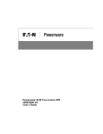
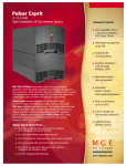
Pulsar MX
5000 RT — UPS
EXB RT — Extended Battery
Transformer 5000
Installation and User Manual
Installation and User Manual
Pulsar MX
Installation and User Manual
Revision History
Pulsar MX Installation and User Manual, 86-87050-00
Revision: A00
ECN#: 004747
04/2006
Revision: A01
ECN#: 004773
05/2006
Copyright © 2006 MGE UPS SYSTEMS, INC.
All rights reserved. Printed in U.S.A.
MGE UPS SYSTEMS, INC.
1660 Scenic Avenue
Costa Mesa, CA 92626
(714) 557-1636
Technical Support:
1-800-523-0142 (during business hours)
Customer Care Center:
1-800-438-7373 (Hours: 24/7)
86-87050-00 A01
Pulsar MX
86-87050-00 A01
Contents
Introduction
..........................................................................................................................1
Important Safety Instructions ..............................................................................................................2
Symbol Usage
..........................................................................................................................3
Presentation
1.1
Standard Positions..........................................................................................................1 — 1
1.2
Rear Panels ..................................................................................................................1 — 2
1.3
Display and Control Panel ............................................................................................1 — 3
1.4
Accessories for Rack Mount ..........................................................................................1 — 3
1.5
Extended Battery (EXB) ................................................................................................1 — 4
Installation
2.1
Unpacking and Contents Check ....................................................................................2 — 1
2.2
Internal Batteries Connection (Battery Start-Up)............................................................2 — 2
2.3
Installation in Tower Position ........................................................................................2 — 2
2.4
Installation in Rack Position............................................................................................2 — 3
2.5
Communication Ports ....................................................................................................2 — 5
2.6
Required Protective Devices and Cable Cross-Sections .............................................. 2 — 6
2.7
Hardwire Connection of Output Power Cable to UPS....................................................2 — 7
2.8
Connection to Output Receptacles ................................................................................2 — 8
2.9
Connection of Extended Battery Module, UPS, and Transformer ................................ 2 — 8
Operation
3.1
Initial Start-Up ................................................................................................................3 — 1
3.2
Final Start-Up Sequence ................................................................................................3 — 1
3.3
Operating Modes ..........................................................................................................3 — 2
3.4
Operation on Battery Power ..........................................................................................3 — 3
3.5
Return to Normal AC Source. ........................................................................................3 — 4
3.6
UPS Shutdown When AC Present ................................................................................3 — 4
3.7
UPS Shutdown When on Battery ..................................................................................3 — 4
Access to Maintenance and Personalization Data
4.1
Display Organization ......................................................................................................4 — 1
4.2
Access to Measurements. ..............................................................................................4 — 1
4.3
Access to UPS Set-Up and Maintenance Using the Control Panel ..............................4 — 1
4.4
UPS Set-Up ..................................................................................................................4 — 2
4.5
Maintenance ..................................................................................................................4 — 3
4.6
Personalization Using External Software ......................................................................4 — 3
Troubleshooting
86-87050-00 A01
5.1
Troubleshooting LEDS (21) and (22)..............................................................................5 — 1
5.2
Troubleshooting Not Requiring MGE UPS SYSTEMS ..................................................5 — 2
5.3
Troubleshooting Requiring MGE UPS SYSTEMS After-Sales Support ........................5 — 3
Contents
ci
Pulsar MX
Life Cycle Monitoring (LCM)
6.1
Description
..................................................................................................................6 — 1
Maintenance
7.1
Hot Swapping the Power Sub-Module ...........................................................................7 — 1
7.2
Hot Swapping the Battery Sub-Module .........................................................................7 — 2
Appendices
Technical Specifications...............................................................................................................8 — 1
MGE Warranty & Proprietary Rights for Single Phase Products
MGE Standard Single Phase Warranty
Proprietary Rights Statement
Customer Care Center - Single Phase Products
Technical Support and Product Services
Who to Contact
Scheduling Field Service Engineer Support
Return Policy for Repair of Single Phase Products (RGA)
Glossary
c ii
Contents
86-87050-00 A01
Introduction
Thank you for selecting an MGE UPS SYSTEMS product to protect your electrical equipment.
The Pulsar MX range has been designed with the utmost care.
We recommend that you take the time to read this manual to take full advantage of the many features of your UPS (Uninterruptible
Power System).
Warning: This is a class A UPS product. In a domestic environment, this product may cause radio interference, in which case, the
user may be required to take additional measures.
If the device must be installed in overvoltage category III or IV environments, additional upstream overvoltage protection must be
provided for.
Before installing Pulsar MX, please read the booklet on the required safety instructions. Then follow the indications in this manual.
To discover the entire range of MGE UPS SYSTEMS products and the options available for the Pulsar MX range, we invite you
to visit our web site at www.mgeups.com or contact your MGE UPS SYSTEMS representative.
Environmental protection
MGE UPS SYSTEMS has implemented an environmental-protection policy.
Products are developed according to an eco-design approach.
Substances
This product does not contain CFCs, HCFCs or asbestos.
Packing
To improve waste treatment and facilitate recycling, separate the various packing components.
◗ The cardboard we use comprises over 50% of recycled cardboard.
◗ Sacks and bags are made of polyethylene.
01
◗ Packing materials are recyclable and bear the appropriate identification symbol.
PET
Material
Abbreviation
Symbol
number
Polyethylene terephthalate
PET
01
High-density polyethylene
HDPE
02
Polyvinyl chloride
PVC
03
Low-density polyethylene
LDPE
04
Polypropylene
PP
05
Polystyrene
PS
06
01
PET
Follow all local regulations for the disposal of packing materials.
End of life
MGE UPS SYSTEMS will process products at the end of their service life in compliance with local regulations.
MGE UPS SYSTEMS works with companies in charge of collecting and eliminating our products at the end of their service life.
◗ Product
The product is made up of recyclable materials.
Dismantling and destruction must take place in compliance with all local regulations concerning waste.
At the end of its service life, the product must be transported to a processing centre for electrical and electronic waste.
◗ Battery
The product contains lead-acid batteries that must be processed according to applicable local regulations concerning
batteries.
The battery may be removed to comply with regulations and in view of correct disposal.
The "Material Safety Data Sheets" (MSDS) for the batteries are available on our web site*.
(*) For more information or to contact the Product Environmental manager, use the "Environmental Form" on the site:
www.mgeups.com -> About us -> Environment.
86-87050-00 A01
Introduction
1
Pulsar MX
IMPORTANT SAFETY INSTRUCTIONS
SAVE THESE INSTRUCTIONS. This manual contains important instructions that should be followed during installation and maintenance of the UPS and batteries.
The Pulsar MX models that are covered in this manual are intended for installation in an environment within 0 to 40° C, free of
conductive contaminant.
This equipment has been tested and found to comply with the limits for a Class A digital device, pursuant to Part 15 of the FCC Rules.
These limits are designed to provide reasonable protection against harmful interference when the equipment is operated in a commercial environment. This equipment generates, uses, and can radiate radio frequency energy and, if not installed and used in accordance
with the instruction manual, may cause harmful interference to radio communications. Operation of this equipment in a residential area
is likely to cause harmful interference in which case the user will be required to correct the interference at his own expense.
Certification Standards
◗
◗
◗
◗
◗
◗
◗
◗
◗
◗
IEEE 587-1980/ANSI C62.41 1980 Standards for Surge Withstand Ability
FCC rules and regulations of Part 15, Subpart J, Class A
UL listed under 1778, Standards for Uninterruptible Power Supply Equipment
IEC 61000-4-2 (ESD): level 4
IEC 61000-4-3 (Radiated field): level 3
IEC 61000-4-4 (EFT): level 4
IEC 61000-4-5 (Fast transients): level 4
IEEE-C6241 Category B (ring wave)
IEC 61000-4-6 (electromagnetic field)
IEC 61000-4-8 (conducted magnetic field)
Safety of persons
◗
◗
◗
◗
The system has its own power source (the battery). Consequently, the power outlets may be energized even if the systems is disconnected
from the AC power source.
Dangerous voltage levels are present within the system. It should be opened exclusively by qualified service personnel.
The system must be properly grounded.
The battery supplied with the system contains small amounts of toxic materials. To avoid accidents, the directives listed below must be observed:
-Never burn the battery (risk of explosion).
-Do not attempt to open the battery (the electrolyte is dangerous for the eyes and skin).
-Comply with all applicable regulations for the disposal of the battery.
-Batteries constitute a danger (electrical shock, burns). The short-circuit current may be very high. Precautions must be taken for all handling:
remove watches, rings, bracelets and any other metal objects, use tools with insulated handles.
-Do not lay tools or metal parts on top of batteries.
Product Safety
◗
◗
◗
◗
◗
◗
◗
◗
◗
The UPS connection instructions and operation described in the manual must be followed in the indicated order.
A protection circuit breaker must be installed upstream and be easily accessible. The system can be disconnected from the AC power source
by opening this circuit breaker.
Check that the indications on the rating plate correspond to your AC powered system and to the actual electrical consumption of all the
equipment to be connected to the system.
Never install the system near liquids or in an excessively damp environment.
Never let a foreign body penetrate inside the system.
Never block the ventilation grates of the system.
Never expose the system to direct sunlight or source of heat.
If the system must be stored prior to installation, storage must be in a dry place.
The admissible storage temperature range is -20ºC to +40ºC.
Special Precautions
◗
◗
◗
All handling operations will require at least two people (unpacking, installation in rack system).
Before and after the installation, if the UPS remains de-energized for a long period, the UPS must be energized for a period of 24 hours, at least
once every 6 months (for a normal storage temperature less than 25°C). This charges the battery, thus avoiding possible irreversible damage.
During the replacement of the Battery Module, it is imperative to use the same type and number of element as the original Battery Module provided
with the UPS to maintain an identical level of performance and safety. In case of doubt, don’t hesitate to contact your MGE representative.
Environment
◗
◗
◗
2
This product has been designed to respect the environment:
It does not contain any Chlorofluorocarbon (CFC) or Hydrochlorofluorocarbon (HCFC).
UPS recycling at the end of service life:
MGE UPS SYSTEMS, INC. undertakes to recycle, by certified companies and in compliance with all applicable regulations,
all UPS products recovered at the end of their service life (contact your MGE UPS SYSTEMS, INC. branch office).
Packing: UPS packing materials must be recycled in compliance with all applicable regulations.
WARNING: This product contains lead-acid batteries. Lead is a dangerous substance for the environment if it is not
properly recycled by specialized companies.
Introduction
86-87050-00 A01
Installation and User Manual
Symbol Usage
Important instructions that must always be followed.
Information, advice, help.
Visual indication.
Action.
Audible signal.
LED off
LED on
86-87050-00 A01
Introduction
3
Pulsar MX
(This page left blank intentionally)
4
86-87050-00 A01
Presentation
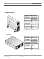
1.1 Standard Positions
Tower Position
Dimensions (H x W x D) in inches/mm
Pulsar MX 5000 RT
Pulsar MX EXB RT
Transformer 5000
17.5 x 5.16 x 29.2/
444.5 x 131 x 741.4
17.5 x 5.16 x 25.6/
444.5 x 131 x 650
17.5 x 3.5 x 25.6/
444.5 x 88.9 x 650
Weights in lbs/kg
Pulsar MX 5000 RT
125/57
Pulsar MX EXB RT
154/70
Transformer 5000
84/38
Rack Position
Dimensions (H x W x D) in inches/mm
Pulsar MX 5000 RT
Pulsar MX EXB RT
Transformer 5000
5.16 x 17.5 x 29.2/
131 x 444.5 x 741.4
5.16 x 17.5 x 25.6/
131 x 444.5 x 650
3.5 x 17.5 x 25.6/
88.9 x 444.5 x 650
Weights in lbs/kg
86-87050-00 A01
Presentation
Pulsar MX 5000 RT
125/57
Pulsar MX EXB RT
154/70
Transformer 5000
84/38
1—1
Pulsar MX
1.2 Rear Panels
Pulsar MX 5000 RT
Pulsar MX EXB RT
Transformer 5000
12
15
LOAD 3 / 120V~,16A
LOAD 4 / 120V~,16A
200-250V~,24A
2
LOAD 3
BREAKER
LOAD 4
BREAKER
1
14
3
4
CAUTION:
DO NOT DISCONNECT
BATTERY CABLE
180VDdc UNDER LOAD
BATTERY
CONNECTOR
5
11
8
16
9
RS-232
BATT. NO.
RPO
10
LOAD 1
120V~,16A
7
LOAD 1
BREAKER
LOAD 2
BREAKER
6
17
13
LOAD 2
120V~,16A
19
240~
208~
INPUT VOLTAGE
SELECTION
SET THIS
SWITCH WHEN
UNPOWERED
BY ALL SOURCES
18
INPUT
BREAKER
12
TRANSFORMER
PROTECTION
(1)
One group of 4 L6-30R outlets for connection of equipment
(2)
Output terminal block
(3)
Normal AC source input cable with L6-30P
(4)
Connector for additional battery module
(5)
Slot for optional communication card
(6)
USB communication port
(7)
RS232 communication port
(8)
Communication port by relay
(9)
1—2
63
64
Connector for Remote Power Off control
(10)
Connector for automatic detection of battery module(s)
(11)
Connectors for automatic detection of battery module(s)
(12)
Connectors for battery modules (to the UPS or to the other battery modules)
(13)
DC Battery circuit breaker
(14)
Resetable 20Amp circuit breakers for NEMA 5-15/20 receptacle
(15)
6 NEMA 15/20 receptacle
(16)
Resetable 20Amp circuit breakers to protect each L5-20R receptacle
(17)
Input cable with L6-30P plug
(18)
Input resetable CB
(19)
2 NEMA L5-20R receptacle
(63)
Input voltage selecting (240V/208)
(64)
Transformer protection CB
Presentation
86-87050-00 A01
Installation and User Manual
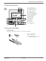
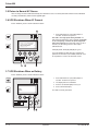
1.3 Display and Control Panel
(20) Load protected LED
(21) Downgraded operation LED
(22) Load not protected LED
(23) Alphanumeric display
(24) Escape (cancel) button
(25) Function buttons (scroll down)
(26) Function buttons (scroll up)
(27) Enter (confirm) button
(28) UPS OFF button
(29) UPS ON button
(30) Rectifier LED
(31) Battery LED
(32) Inverter LED
(33) Bypass LED
(34) Load supplied LED
1.4 Accessories for Rack Mount
Rack Mounting Kit
Telescopic rails for Pulsar MX RT mounting in 19’’ enclosure with mounting hardware
(35) Front mounting bracket
(36) Rear support bracket
35
(37) Telescopic rails, 639 mm to 1005 mm
length (27.36’’ to 39.96’’)
36
37
86-87050-00 A01
Presentation
1—3
Pulsar MX
1.5
Extended Battery (EXB)
Pulsar MX RT offers a standard backup time of 5 minutes at full load. To increase backup time, it is possible to connect
Pulsar MX EXB RT modules to the UPSs for backup times up to 62 minutes (at full load).
Battery extensions for Pulsar MX RT
Pulsar MX
5000 RT
Pulsar MX 5000 RT:
5 min
Pulsar MX
EXB RT
Pulsar MX
EXB RT
22 min
41 min
Pulsar MX
EXB RT
62 min
Battery Integration System Kit with Casters (86005)
The Battery Integration System is intended
for extended backup time configurations
to conveniently stack and secure up to 5
modules on the same cart (swivel wheels
with brakes, leveling feet, seismic side
panels, plates to lock modules, and screws
included).
Optional battery extension cable (6 ft/1.8 m)
This extended battery cable will be used instead of the standard battery cable when battery modules are distant from each
other (located in two different enclosures, for instance).
1—4
Presentation
86-87050-00 A01
Installation
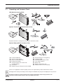
2.1
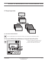
Unpacking and Contents Check
UPS Module Contents (87050)
46
47
option
(66102)
Optional Transformer Module Contents (87102)
54
51
49
43
45
Step down transformer is designed to provide isolated 120 volts AC outlets.
Optional Battery Module Contents (87103)
51
50
52
53
54
53
43
(40)
(41)
(42)
(43)
(45)
Pulsar MX 5000 UPS
Two sets of tower stands
RS232 communications cable
Product documentation
Telescopic rails for rack enclosure with
mounting hardware
(46) Screw driver
(47) Solution-Pac power management suite CD-ROM
(48)
(49)
(50)
(51)
(52)
(53)
(54)
Network Management card (optional)
Transformer 5000
Pulsar MX EXB RT battery module
Tower stand expanders
Battery cable
Battery communication cable
Stabilizer bracket (4 screws included)
Please see the appropriate manual for packing contents of the optional battery module and transformer module.
i
Packaging must be destroyed according to waste management standards. Recycling icons are displayed for easy selection.
A dangerous voltage is present inside the power module and the battery module. Any operations to be
carried out on these modules must be done so by qualified personnel.
86-87050-00 A01
Installation
2—1
Pulsar MX
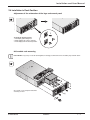
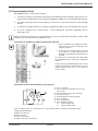
2.2 Internal Battery Connection (Battery Start-up)
1. Remove the two mounting screws (59) to
free the battery disconnect switch (60).
59
2. Push the battery disconnect switch so that
you can read “Connected”.
RS-232
BATT. NO.
RPO
3. Secure the two mounting screws (59).
~,24
A
:
ONECT
UTI
NN
CO
T DIS BLE
NO Y CA
DO TERLOAD
BATDER
Y R
TER TO c UN
BATNNEC VDd
180
CO
CA
0V
0-25
20
60
Input Cable L6-30P
2.3 Installation in Tower Position
Follow steps 1 to 3 in the illustration below to adjust the tower stands for the upright position.
6 inches
17.7 inches
Always keep 6 inches free space behind the UPS rear panel. The distance between the tower stands should
be 17.7 inches.
2—2
Installation
86-87050-00 A01
Installation and User Manual
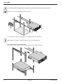
2.4 Installation in Rack Position
Adjustment of the orientation of the logo and control panel
1
To adjust the display position:
1. Pull display panel straight out.
2. Rotate display 90º counter clockwise.
3. Push display back into desired position.
2
3
UPS module rack mounting
Pulsar MX RT is very heavy. To ease its rack integration, we strongly recommend to remove the battery tray as shown below.
See Section 7.2 for complete instructions
on battery removal.
86-87050-00 A01
Installation
2—3
Pulsar MX
Do not install the UPS or battery module in hermetic closed environments without any exchange of air.
Follow steps 1 to 4 for rack mounting the UPS onto the rails.
The rails and the necessary mounting hardware are supplied by MGE UPS SYSTEMS.
Note for step 1: It is possible to adjust the position of both front mounting brackets.
Rear bracket system (included with rail kits)
To be used if you need to move the rack enclosure with UPS already rack-mounted inside.
2—4
Installation
86-87050-00 A01
Installation and User Manual
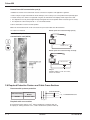
2.5 Communication Ports
Pulsar MX RT provides 4 communication methods.
1.
The RS232 port provides communications using MGE UPS SYSTEMS Serial HID UPS transfer (SHUT) protocol. The
SHUT protocol is compatible with the power management applications available on the enclosed Solution-Pac 2 CD-Rom.
2.
The Output contacts port is used for basic signaling or for protection of IT systems like IBM iSeries (formerly AS400)
and more.
3.
The USB port is compatible with the power management applications available on the enclosed Solution-Pac 2 CD-Rom.
4.
The slot is compatible with the optional 66102 — Network Management Card (NMC) 2006 Edition and the
66103-Status Card.
Note All communications options can be used simultaneously except for the SHUT RS232 and USB port. If both the USB
and SHUT ports are connected then the USB takes control.
Connection to the RS232 or USB communication port (42)
1 Connect the RS232 (42) or USB (44) communication cable to the serial or USB port on the
computer equipment.
2. Connect the other end of the RS232 cable (42)
to the RS232 (7) communication port or the
USB cable (not included) to the USB port (6) on
the UPS.
The UPS can now communicate with various MGE
UPS SYSTEMS power management application
software.
Please note that Personal Solution-Pac can be used to
configure (personalize) the UPS parameters such as
voltage, frequency, battery test, etc. See section 4.6
for more details.
Connection to the communication port by relays (8)
◗ Pin 1, 2: not used,
◗ Pin 3: Remote Power Off signal (5 to 27 V DC,
10 m A max),
◗ Pin 4: Operation on mains (not on battery),
◗ Pin 5: User common,
◗ Pin 6: Operation on automatic by-pass,
◗ Pin 7: Low battery,
◗ Pin 8: Load protected,
◗ Pin 9: Operation on battery.
n.o:
contact normally open.
n.c:
contact normally closed.
8
When the status is active, the contact between the common (Pin 5) and the relevant information pin is closed.
Output relays specifications:
◗ Voltage: 48 V DC max,
◗ Current: 2 A max,
◗ Power: 62.5 VA, 30 W.
Example: for 48 V DC, Imax=625 mA
86-87050-00 A01
Installation
2—5
Pulsar MX
Remote Power Off communication port (9)
Installation of a Remote Power Off function must be carried out in compliance with applicable regulations.
In order to fully de-energize Pulsar MX RT with the RPO port, it is necessary to use a two-position switch (Normally Open
or Closed contact). Once switch is energized/de-energized, the UPS shuts off the display and the output of the UPS.
◗
◗
The output devices can be powered again through auto bypass when the two-position switch is released (open or closed).
The output devices will remain powered < 1 sec. after RPO activation.
Push the start button to return to normal operation.
Note: The internal batteries will remain connected to the power sub-module after RPO activation.
The cable is not included.
Remote power off contact normally open (9)
Installation of optional
communication card (66102)
RJ12
+
5 V DC to 27 V DC
_
Remote power off contact normally closed (9)
RJ12
5 VDC to 27 VDC
+
_
◗ Signal:
activation voltage: 5 V DC to 27 V DC,
current: 10 mA max.
2.6 Required Protective Devices and Cable Cross-Sections
Recommended upstream protection
2 poles circuit breaker
UPS Power Rating
Upstream Circuit
Breaker
5000 RT
D curve - 35A
L1
L2 (N)
To UPS Normal AC source
G L2 (N) L1
Required cable cross-sections
◗ Terminal-block cable capacity: 6 mm2, solid or stranded wire (maximum AWG 10).
◗ Capacity for earthing conductor: 6 mm2 , solid or stranded wire (maximum AWG 10).
2—6
Installation
86-87050-00 A01
Installation and User Manual
2.7
Hardwire Connection of Output Power Cable to UPS
◗ This type of connection must be carried out by qualified electrical personnel.
◗ Before carrying out any connection, check that the battery circuit breaker and the upstream protection device
(Normal AC source) is open "0" (off).
1. Remove the top of the terminal box cover
(2 screws) with the included screwdriver.
2. Insert the output cable/conduit (provided by others)
through the cable knockout (2).
3. Connect the outlet cable to the output terminal block.
RS-232
BATT. NO.
RPO
4. Tighten the cable/conduit flange and refit the
terminal box cover by means of the 2 screws.
0V
Always connect the ground wire first.
:T
NEC
TIO
NN
CO
T DIS BLE
NO Y CAD
DO TERLOA
BATDER
Y
TER TORc UN
BATNNEC VDd
180
CO
CAU
0-25
20
4A
~,2
3
2
1
RS-232
BATT. NO.
RPO
Note: 10’ Input cable with L6-30P (3) comes attached
by MGE UPS SYSTEMS. Output cable/conduit (2) is
not included (provided by others).
Output Terminal
50
:T
NEC
TIO
NN
CO
T DIS BLE
NO Y CAD
DO TERLOA
BATDER
Y R
TER TO c UN
BATNNEC VDd
180
CO
CAU
0-2
20
A
,24
V~
3
2
2&3
L1
RS-232
BATT. NO.
RPO
GND L2(N)
0V
:T
NEC
TIO
NN
CO
T DIS BLE
NO Y CAD
DO TERLOA
BATDER
Y R
TER TO c UN
BATNNEC VDd
180
CO
CAU
0-25
20
4A
~,2
3
2
4
86-87050-00 A01
Installation
2—7
Pulsar MX
2.8 Connection to Output Receptacles
1. Connect the equipment to the UPS 4 NEMA L6-30R.
RS-232
BATT. NO.
RPO
If more than one load is connected to the
UPS, the total capacity of the loads should
not exceed 30 Amps.
0V
A
~,24
:
ONECT
UTI
NN
CO
T DIS BLE
NO Y CA
DO TERLOAD
BATDER
Y R
TER TO c UN
BATNNEC VDd
180
CO
CA
0-25
20
2.9 Connection of Extended Battery Module, UPS, and Transformer
BATTERY
MODULE
BATTERY
MODULE
UPS MODULE
Pulsar MX
TRANSFORMER
MODULE
52
4
TRANSFORMER
INPUT CABLE
53
53
11
53
10
13
12
1. Check that the battery circuit breaker(s) (13) is OFF ("0" position).
2. Connect the battery power cable (52) to the connector (4) of the power module and to the connector (12) of the battery module.
3. Connect the battery detection cable (53) to the connector (10) of the power module and to the connector (11) of the battery module.
4. Switch on the battery circuit-breaker(s) (13).
2—8
Installation
86-87050-00 A01
Operation
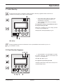
3.1 Initial Start-Up
To ensure that your system is configured in complete accordance with safety regulations and to benefit from the
manufacturer’s warranty, please contact Technical Support.
22
1. Check that the battery disconnect switch (60)
on top cover is connected (see section 2.2
Internal Battery Connection).
2. Set the upstream circuit breaker (not included)
to the on position.
The equipment is powered via the Normal AC source,
but not protected by the UPS.
Batteries are recharging, an 8 hour recharge period is
necessary to get full backup time.
LED (22) is ON, LEDs (33) and (34) are green.
33
34
UPS Set-Up
i
If UPS personalization is desired, it is advised to enter the personalization mode at this time (see the 4.4
"Personalization" section).
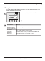
3.2 Final Start-Up Sequence
20
21
22
3. Press and hold the "I" (on) button (29) for 3 seconds.
The buzzer beeps once, and after UPS internal test
sequence, the LED (20) is ON.
LEDs (30), (32), (34) are green.
The equipment is protected by the UPS.
If LED (21) or (22) is ON, an alarm has occurred (see the
"troubleshooting" section).
30
86-87050-00 A01
32
34
29
Operation
3—1
Pulsar MX
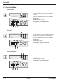
3.3 Operating Modes
Normal mode
This is the standard operating mode, set by default in
the factory.
Under normal condition (Normal AC source available):
LED (20) is ON.
LEDs (30), (32), (34) are green.
The equipment is protected by the UPS.
ECO mode
The main advantage of the Eco mode (see glossary) is
that it reduces the consumption of electrical power.
Under normal condition (Normal AC source available):
LED (20) is ON.
LEDs (33), (34) are green.
The equipment is supplied in ECO mode.
AC out of tolerance
If normal AC source is out of tolerance:
LEDs (20), (21) are ON.
LEDs (30), (32), (34) are green.
The equipment is protected by the UPS.
3—2
Operation
86-87050-00 A01
Installation and User Manual
3.4 Operation on Battery Power
When the Normal AC source is not available, the load continues to be protected by the UPS.
Power is supplied by the battery.
Transfer to battery power
LEDs (20), (21) are ON.
LEDs (31), (32), (34) are green.
The audible alarm beeps every 10 seconds.
The equipment is protected by the UPS and supplied
by the battery.
The display indicates the battery remaining backup time.
Low battery warning
LEDs (20), (21) are ON.
LEDs (31), (32), (34) are green.
The audible alarm beeps every 3 seconds.
The remaining battery power is low.
Shut down all applications on the connected equipment
because automatic UPS shutdown is imminent.
End of backup time
LED (22) is ON.
LED (34) is red.
The audible alarm beeps continuously.
The equipment is not powered.
The UPS displays "End of backup time Battery low".
86-87050-00 A01
Operation
3—3
Pulsar MX
3.5 Return to Normal AC Source
After an outage, the UPS restarts automatically when Normal AC source is restored (unless this function has been disabled
via UPS personalization) and the load is supplied again.
3.6 UPS Shutdown When AC Present
Before shutdown, please read ALL instructions below:
22
1. Press and hold the "0” (off) button (28) for 3
seconds. The buzzer beeps once.
The load is no longer protected by the UPS. It is
powered via the Normal AC source (bypass). If the UPS
is set in frequency converter mode, the equipment
will not be powered. If the Normal AC source is out of
tolerance, the UPS will generate a 10ms output
calibrated break.
ON AUTO BYPASS
LEDs (22) is ON, LEDs (33) and (34) are green.
For a full shutdown of UPS and connected load, the
upstream circuit breaker (not included) should be set to
the off position or remove the Normal AC source.
33
34
28
3.7 UPS Shutdown When on Battery
Before shutdown, please read ALL instructions below:
1. Press and hold the "0” (off) button (28) for 3
seconds. The buzzer beeps once.
2. The display asks for confirmation.
3. Press the scroll button (25) to select yes.
4. Press confirm button (27).
NO
YES
The UPS is now fully shut down.
25
3—4
27 28
Operation
86-87050-00 A01
Access to Maintenance and Personalization Data
4.1 Display Organization
Status and Alarms
Measurements
UPS input measurements
UPS output measurements
Battery measurements
UPS Set-up
Local settings
Output settings
ON/OFF settings
Battery settings
Maintenance
Model
Alarm History
Manual battery test
Led and Buzzer test
LCM
Statistics
Operation limits
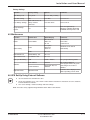
4.2 Access to Measurements
Press the scroll button (25) to access measurements for voltage, current, frequency, power output and battery capacity.
4.3 Access to UPS Set-Up and Maintenance Using the Control Panel (23)
◗ Press the scroll button (25) a number of times to
point to the UPS set-up or Maintenance menu.
◗ Press the “Enter” button (27) to get access.
86-87050-00 A01
Access to Maintenance and
Personalization Data
4—1
Pulsar MX
4.4 UPS Set-Up
Local Settings
Function
Factory Setting
Options
Language
English
French, German, Italian, Portuguese, Spanish
Date/Time Format
International format
(DD-MM-YYYY/HH :MM)
US (MM-DD-YYYY/HH:MM AM/PM)
Date/Time Change
GMT + 1
(Continental Europe)
MM-DD-YYYY/HH :MM adjustable
Audible Alarm
Yes
No
Function
Factory Setting
Options
Output Voltage
208V
200V / 230V / 220V /
240V / 250V
Freq Converter
Disabled
Enabled
Output Frequency
60 Hz
50 Hz
User selectable under frequencyconverter mode
Eco Mode
Disabled
Enabled
See glossary
Slew rate
1 Hz/sec.
0.5 Hz/sec.
Bypass Transfer
Yes
No
Transfer to bypass if Normal AC
source is out of tolerance
Interrupt Time
10 ms
20 ms, ...... , 200 ms
Break time calibration during load
transfer on Normal AC source out
of tolerance
Overload Prealarm
105 %
40%, 50%, 70%
Alarm if threshold is overrun
Function
Factory Setting
Options
Comments
Cold Start
Disabled
Enabled
Start on battery
Output Settings
Comments
ON/OFF Settings
4—2
Forced Reboot
Enabled
Enabled
Enables automatic restart of the
system even if Normal AC source
is restored before the end of the
shutdown sequence
Auto Restart
Enabled
Disabled
UPS restarts automatically when
Normal AC source is restored
Energy Saving
Disabled
Enabled
Automatic shutdown on battery if
output load level < 10%
Sleep Mode
Enabled
Disabled
Remote Command
Enabled
Disabled
Access to Maintenance and
Personalization Data
Enables consideration of
shutdown or restart orders from
software to be authorized
86-87050-00 A01
Installation and User Manual
Battery Settings
Function
Factory Setting
Options
Comments
Auto Battery Test
Every week
No test / daily / monthly
Low Batt warning
20%
0 to 100%
1% increment
User Battery Settings
UPS reads number of
battery modules
connected
From 0 to 40 Ah
5 Ah increment
Deep Discharge
Protect
Yes
No
Protection against deep
discharge. If disable, MGE UPS
SYSTEMS warranty will be void
Function
Sub-Function
Option/Display
Comments
Model
Power Module
SN: xxxxxxxxx
SOFT: xxx
NT: xxx
Serial number
Soft version
Technical level
Read
Description
Date Hour
Alarm xxx
10 alarms can be stored
automatically
Erase
No / Yes
Manual Batt Test
Manual Battery Test
No / Yes
Led & Buzzer Test
Led & Buzzer Test
No / Yes
Life Cycle Monitoring
LCM
Enable / Disable
Life cycling monitoring alarms
Auto Statistics
Statistics
Custom Statistics
Reset Date: No, Yes
Statistics
You need to register at
www.mgeups.com/Icm to get the
code and get access to free
statistics
4.5 Maintenance
Alarm History
Statistics
Operation Limits
Operation Limits
Automatic alarms displayed when
UPS is operating near the limits
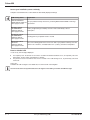
4.6 UPS Set-Up Using External Software
◗
Insert the Solution-Pac CD-ROM in the drive.
◗
On the first navigation screen, select "Point to Point solution" and follow the instructions on how to install the
Personal Solution-Pac software.
◗
Then select "Settings", "Advanced settings" and "UPS settings".
Note: This feature is only supported through Windows and the RS232 communication.
86-87050-00 A01
Access to Maintenance and
Personalization Data
4—3
Pulsar MX
(This page left blank intentionally)
4—4
86-87050-00 A01
Troubleshooting
5.1 Troubleshooting LEDS (21) and (22)
If LED (21) is ON:
The equipment is protected by the UPS but the
operation is downgraded.
If LED (22) is ON:
The equipment is no longer protected by the UPS.
5.2 Troubleshooting Not Requiring MGE UPS SYSTEMS After-Sales Support
ENVIRONMENT FAULT
27
Press the "Enter" button (27) to display the details below:
Displayed details
Signification
Correction
NO BATTERY
The battery is incorrectly connected
Check battery connections (see section 2.9)
I/O BAD CONNECTION
AC source is not connected to the
correct terminals
Check AC wiring
NO POWER MODULE
The power sub-module is not
inserted
Check power sub-module connections
(see section 7.1)
NO BATTERY MODULE
The battery sub-module is
incorrectly connected
Check battery connections (see section 7.2)
INV THERM OVERLOAD
The UPS shuts down automatically
because of a major overload
Check the power drawn by the connected devices
and disconnect any non-priority devices
INVERT LIMITATION
Short circuit conditions on output
devices
Check the installation at the UPS output (wiring, fault
equipment)
86-87050-00 A01
Troubleshooting
5—1
Pulsar MX
5.3 Troubleshooting Requiring MGE UPS SYSTEMS After-Sales Support
xxx FAULT
27
Display
Signification
Correction
POWER MODULE FAULT
The battery is incorrectly connected.
Internal power sub-module fault
detected. Use "Enter" button (27) to
display details.
Call the after-sales support department at
1-800-523-0142. Follow the power sub-module
replacement procedure (see sections 7.1 and 7.2)
BATT MODULE FAULT
Battery fault detected during the battery test. Use "Enter" button (27) to
display details.
Call the after-sales support department at
1-800-523-0142. Follow the battery sub-module and
battery module replacement procedure (see section 7.2)
FRAME FAULT
Internal chassis fault detected. Use
"Enter" button (27) to display details.
Call the after-sales support department at
1-800-523-0142. Follow the frame replacement
procedure (see sections 7.1 and 7.2)
Note: In case of multiple fault, press the "Enter" button (27) and the scroll button (25) to get access to further details.
5—2
Troubleshooting
86-87050-00 A01
Life Cycle Monitoring (LCM)
6.1 Description
This function, embedded in the UPS, displays messages on screen, and communication channels, at every
important stage of the UPS’s life, allowing you to:
Press the "Enter" button (27) to display LCM
warning details.
Get free offers
LCM warning details
Signification
3 MONTHS FREE WARRANTY
EXTENSION FOR PRODUCT
REGISTRATION CONTACT
MGE AT www.mgeups.com/lcm
Get free offer after registration at: www.mgeups.com/lcm
FREE STATISTIC
FEATURE FOR
PRODUCT WEB
REGISTRATION
CONTACT MGE AT
www.mgeups.com/lcm
Get free offer after registration at: www.mgeups.com/lcm
These statistics will allow you to have an accurate follow-up (on the display) of the
major environmental parameters of your installation:
◗ Autonomy, time with mains 2 out of tolerance, overloads number, load level in %,
Battery ambient temperature, time on inverter, time on mains 2
86-87050-00 A01
Life Cycle Monitoring (LCM)
6—1
Pulsar MX
Secure your installation power continuity
Anticipate needed maintenance actions thanks to automatically displayed warnings:
LCM warning details
Signification
END OF WARRANTY
Get your product warranty extension by contacting MGE UPS SYSTEMS at www.mgeSOON CONTACT MGE AT
ups.com/lcm
www.mgeups.com/lcm
BATTERY CHECK
RECOMMENDED
CONTACT MGE AT
www.mgeups.com/lcm
Battery is approaching its reliability end of life. Risk of dramatically reduced
backup time
TECHNICAL CHECK
RECOMMENDED
CONTACT MGE AT
www.mgeups.com/lcm
Wearing parts of your product must be checked
OPERATION LIMITS
REACHED.
CONTACT MGE AT
www.mgeups.com/lcm
One of the following parameters is close to the limit of your product: Autonomy, time with
mains 2 out of tolerance, overloads load level in %, battery environment temperature
Reset or disable LCM
In case of any LCM messages displayed:
◗
◗
For temporary reset: Press ESC for more than 3 seconds in the Status and Alarm screen, to temporarily cancel the
alarm status. The alert will be repeated twice in 30 days.
For permanent reset: Press ENT for more than 3 seconds in the LCM warning screen, to permanently cancel this
LCM event.
At any time:
To Disable all LCM messages select "disable all", in LCM menu with LCD navigation.
You will not be aware of any LCM events that can happen on the UPS if you disable all LCM messages.
6—2
Life Cycle Monitoring (LCM)
86-87050-00 A01
Maintenance
7.1 Hot Swapping the Power Sub-Module
This operation must be carried out by qualified electrical personnel only.
This operation can be performed without interrupting the equipment.
Disconnecting the power sub-module (87100):
1. Remove the 6 mounting screws to free the main front
panel bezel.
2. Place the front panel above the UPS.
3. Remove the 2 mounting screws on each side of the
power sub-module.
4. Withdraw the power sub-module.
Note: There is a safety pin at the rear of the module. Lift
the sub-module slightly and the sub-module will slide out
(follow the arrow in the diagram).
When reconnecting the sub-module, carry out the above
instructions in reverse order. A red button will be
depressed behind plate 3, reestablishing connection.
Reconnecting the power sub-module:
◗
◗
Carry out the above instructions in reverse order.
Replace the faulty power sub-module by another one with same power rating (Pulsar MX 5000).
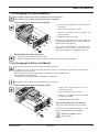
7.2 Hot Swapping the Battery Sub-Module
This operation must be carried out by qualified electrical personnel only.
The battery can cause electrocution and high short-circuit currents. The following safety cautions are required before
servicing the battery components:
◗ Remove watches, rings, bracelets and all other metal objects from the hands and arms,
◗ Use tools with an insulated handle.
This operation can be performed without interrupting the equipments.
This operation must be carried out by qualified electrical personnel only.
Disconnecting the battery sub-module (87101):
1. Remove the 6 mounting screws to free the
main front panel bezel.
2. Place the front panel above the UPS.
3. Remove the 4 mounting screws on the sides of
the battery sub-module.
4. Withdraw the battery sub-module.
Reconnecting the battery sub-module:
Carry out the above instructions in reverse order.
To ensure safety and high performance, use only
batteries supplied by MGE UPS SYSTEMS.
Caution! The battery is heavy
(approx. 60 lbs.).
86-87050-00 A01
Maintenance
7—1
Pulsar MX
86-87050-00 A01
Appendix
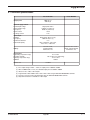
8.1 Technical specifications
Pulsar MX 5000
5000 VA (1) /
4500 W (2)
Output power
Electrical supply network
◗ Rated input voltage
◗ Input voltage range
◗ Frequency
◗ Power factor
◗ Leakage current
Load output
◗ Voltage
◗ Frequency
◗ Harmonic distortion
◗ Overload capacity
Pulsar MX EXB
Single phase 208 V
120/156 V to 280 V (3)
50/60 Hz (autoselect)
> 0.99
7 mA
Single phase 208 V ±3% (4)
50/60 Hz ±0,5% (5)
< 3%
105% continuous, 110% 2min,
125% 1min, > 150% 0.5s
Battery
15 x 12V - 5 Ah,
sealed lead acid,
maintenance free
Environment
◗ Operating temperature range
◗ Relative humidity
◗ Storage temperature range
◗ Altitude
◗ Noise level
Two 15 x 12 V - 5 Ah
strings, sealed lead acid,
maintenance free
0°C to 40°C
20% to 90% (non-condensing)
-25°C to 40°C
1000 m
< 45 dBA
(1) If the output voltage is 200V — 250V, the output power is 5000VA / 4500W.
(2) With one EXB module or more, the standard output power is 5000VA / 4000W.
(3) Values for 70% / 100% of UPS output.
(4) Programmable: 200V / 208V / 220V / 230V / 240V / 250V using the Personal Solution-Pac software.
(5) Frequency-converter mode is programmable using the Personal Solution-Pac software.
(6) Step-down transformer is available for 120V output.
86-87050-00 A01
Appendix
8—1
Pulsar MX
MGE Warranty & Proprietary Rights for Single Phase Products
Standard Warranty Form (Applicable within the United States, Canada and Mexico)
MGE Standard Single Phrase Warranty
MGE UPS SYSTEMS, INC. (“MGE”) warrants single phase products manufactured by MGE to be free
from defects in materials and workmanship for the following applicable time periods beginning with
the date of purchase by or for the first end user (“Purchaser”):
The Pulsar MX is covered by a two (2) year warranty period:
Any defects in materials or workmanship must be reported to MGE within the applicable warranty period. Where labor is not
included in the warranty, any labor performed by MGE shall be billed to Purchaser at, and Purchaser agrees to pay, MGE’s
standard labor rates then in effect for all warranty work performed hereunder. MGE shall have the sole right to determine if any
defective parts are to be repaired at the job site or whether they are to be returned to the factory for repair or replacement. All
items returned to MGE for repair or replacement must be sent freight prepaid to its factory. Purchaser must obtain MGE’s Return
Goods Authorization (“RGA”) prior to returning items. The conditions stated herein must be met for MGE’s warranty to be valid.
MGE will not be liable for any damage done by unauthorized repair work, unauthorized replacement parts, from any misapplication of the subject product, for damage due to accident, abuse, or act of God (such as earthquake, flood, inclement weather, rain
or fire), or relating to Purchaser ’s failure to follow proper environmental conditions for the product.
In no event shall MGE be liable for loss, damage, or expense directly or indirectly arising from the use of or any defects in the
subject product, or from any other cause, except as expressly stated in this warranty. EXCEPT AS EXPRESSLY STATED IN THIS
WARRANTY, MGE UPS SYSTEMS, INC. MAKES NO WARRANTIES, EXPRESS OR IMPLIED, INCLUDING ANY WARRANTY AS
TO MERCHANTABILITY OR FITNESS FOR A PARTICULAR PURPOSE OR USE OR NON-INFRINGEMENT. MGE is not liable for
and Purchaser waives any right of action it has or may have against MGE for any consequential or special damages arising out
of any breach of warranty, and for any damages Purchaser may claim for damage to any property or injury or death to any person
arising out of its purchase or the use, operation or maintenance of the subject product. In no event will MGE be liable for any
labor subcontracted or performed by Purchaser for preparation of the warranted item for return to MGE’s factory or for preparation work for field repair or replacement, and MGE will not be responsible to pay any invoice therefore.
This warranty shall be exclusive of any and all other warranties express or implied and may be modified only by a writing signed
by an authorized officer of MGE UPS SYSTEMS, INC. This warranty shall extend to the Purchaser but to no one else.
Accessories supplied by MGE, but manufactured by others, carry any warranty the manufacturers have made to MGE, and which
can be passed on to Purchaser.
MGE UPS SYSTEMS, INC. makes no warranty with respect to whether the products sold hereunder infringe any patent, U.S. or
foreign, and Purchaser represents that any specially ordered products do not infringe any patent. Purchaser agrees to indemnify
and hold MGE UPS SYSTEMS, INC. harmless from any liability by virtue of any patent claims where Purchaser has ordered a
product conforming to Purchaser ’s specifications, or conforming to Purchaser ’s specific design.
Purchaser has not relied and shall not rely on any oral representation regarding any products sold hereunder and any oral
representation shall not bind MGE UPS SYSTEMS, INC. and shall not be part of any warranty
There are no warranties which extend beyond the description on the face hereof. In no event shall MGE UPS SYSTEMS, INC. be
responsible for consequential damages or for any other damages except as expressly stated herein.
Proprietary Rights Statement
The information in this manual is the property of MGE UPS SYSTEMS, INC., and represents a proprietary article in which MGE
UPS SYSTEMS, INC. retains any and all intellectual property rights, including exclusive rights of use and/or manufacture and/or
sale. Possession of this information does not convey any permission to reproduce, print, manufacture or have made the article
or articles shown herein. Such permission may be granted only by specific written authorization signed by an authorized officer
of MGE UPS SYSTEMS, INC.
IBM, PC-AT, ES/9000, and AS/400 are trademarks of International Business Machines Corporation. MGE and MGE UPS
SYSTEMS are trademarks of MGE UPS SYSTEMS, INC. Other trademarks that may be used herein are owned by their respective companies and are referred to in an editorial fashion only.
For Single Phase Warranty applicable outside of the United States, Canada and Mexico, refer to Single Phase International
Warranty.
86-87050-00 A01
MGE Customer Care Center - Single Phase Products
Technical Support and Product Services
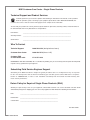
?
Technical questions? If you encounter a problem while following the instructions in this manual, or have questions
about the operation, repair, or servicing of your equipment, please direct calls to MGE UPS SYSTEMS, INC.
Customer Care Center or visit our web site www.mgeups.com for complete service information.
To insure that your questions are correctly answered, please obtain the part number, assembly number, and serial number of
the unit and include them in any discussions or correspondence.
Part Number:
_____________________________________________________________________
Assembly Number:
_____________________________________________________________________
Serial number:
_____________________________________________________________________
Who To Contact
Technical Support:
1-800-523-0142 (during business hours)
Customer Care Center:
1-800-438-7373 (Hours: 24/7)
Customer FAQ
or International calls:
1-714-557-1636
Commitment: MGE UPS SYSTEMS, INC. is committed to providing easy to access factory trained experts that will provide
responses to any questions that you might have.
Scheduling Field Service Engineer Support
Scheduling of the MGE Field Service Engineers typically should be done 7 to 10 days before they are required
on-site. If the startup of the UPS is critical to maintaining your schedule, please call the MGE toll free telephone
number at 1-800-438-7373, to insure a safe installation and startup that will maintain the MGE warranty and
insure smooth performance
Return Policy for Repair of Single Phase Products (RGA)
Should you require factory service for your equipment, contact MGE Customer Care Center and obtain a Return Goods
Authorization (RGA) prior to shipping your unit. Never ship equipment to MGE without first obtaining an RGA number.
Date:
______________________________________________________
RGA Number:
______________________________________________________
Contact Name: ______________________________________________________
Rev A00 5/2005
86-87050-00 A01
Pulsar MX
86-87050-00 A01
Glossary
Backup time
Time that the connected equipment can operate on battery power.
Bypass AC source
Source supplying the bypass line. The equipment can be transferred to the bypass line if an
overload occurs on the UPS output, for maintenance or in the event of a malfunction.
ECO mode
Operating mode by which the equipment is supplied directly by the AC source if it is within the
tolerances defined by the user. This mode reduces the consumption of electrical power.
Equipment
Devices or systems connected to the UPS output.
Normal (double
conversion) mode
The normal UPS operating mode in which the AC source supplies the UPS which in turn
supplies the connected equipment (after electronic double conversion).
Frequency converter
Operating mode used to convert the AC-power frequency between the UPS input and output
(50 Hz -> 60 Hz or 60 Hz -> 50 Hz).
Normal AC source
Normal source of power for the UPS.
Low-battery warning
This is a battery-voltage level indicating that battery power is low and that the user must take
action to prevent the imminent break in the supply of power to the load.
Relay contacts
Contacts supplying information to the user in form of signals.
Personalization
It is possible to modify certain UPS parameters set at the factory. Certain UPS functions can
also be modified by the MGE UPS SYSTEMS power management products to better suit user
needs.
UPS
Uninterruptible Power System.
86-87050-00 A01
Glossary
G—1
Pulsar MX
Notes:
86-87050-00 A01
w w w. m g e u p s . c o m
Contact MGE
United States
MGE UPS SYSTEMS
1660 Scenic Ave.
Costa Mesa, CA 92626
Tel: (714) 557-1636
(800) 523-0142
Fax: (714) 557-9788
email: [email protected]
www: mgeups.com
Canada
MGE UPS SYSTEMS
#9, 2789 Thamesgate Drive
Mississauga, ON L4T 4E8
Tel: (905) 672-0990
(877) 672-0990
Fax: (905) 672-7667
email: [email protected]
www: mgeups.com
Latin America and
Other International
MGE UPS SYSTEMS
1660 Scenic Ave.
Costa Mesa, CA 92626
Tel: (714) 513-7831
(800) 523-0142 ext. 7831
Fax: (714) 434-0199
email: [email protected]
www: mgeups.com
1 6 6 0 S c e n i c Av e n u e , C o s t a M e s a , C a l i f o r n i a 9 2 6 2 6 • ( 7 1 4 ) 5 5 7 - 1 6 3 6