1
www.eaton.com
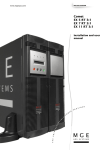
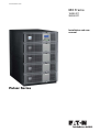
MX Frame
15000 RT
20000 RT
Installation and user
manual
Pulsar Series
Introduction
Thank you for selecting an EATON product to protect your electrical equipment.
The MX range has been designed with the utmost care.
We recommended that you take the time to read this manual to take full advantage of the many features of your UPS
(Uninterruptible Power System)
Warning: this is a class A UPS product. In a domestic environment, this product may cause radio interference, in wich
case, the user may be required to take additional measures.
Output cables should not be longer than 10 meters.
If the device must be installed in overvoltage category III or IV envoronments, additional upstream overvoltage
protection must be provided for.
Before installing MX, please read the booklet on the required safety instructions. Then follow the indications in this
manual.
To discover the entire range of EATON products and the options available for the MX range, we invite you to visit
our web site at www.eaton.com or contact your EATON representative.
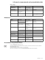
Environmental protection
EATON has implemented an environmental-protection policy.
Products are developed according to an eco-design approach.
Substances
This product does not contain CFCs, HCFCs or asbestos.
Packing
To improve waste treatment and facilitate recycling, separate the various packing components.
◗ The cardboard we use comprises over 50% of recycled cardboard.
◗ Sacks and bags are made of polyethylene.
◗ Packing materials are recyclable and bear the appropriate identification symbol
.
Material
Abbreviation
Symbol
number
Polyethylene terephthalate
PET
01
High-density polyethylene
HDPE
02
Polyvinyl chloride
PVC
03
Low-density polyethylene
LDPE
04
Polypropylene
PP
05
Polystyrene
PS
06
Follow all local regulations for the disposal of packing materials.
End of life
EATON will process products at the end of their service life in compliance with local regulations.
EATON works with companies in charge of collecting and eliminating our products at the end of their service life.
Product
The product is made up of recyclable materials.
Dismantling and destruction must take place in compliance with all local regulations concerning waste.
At the end of its service life, the product must be transported to a processing centre for electrical and electronic waste.
◗
Battery
The product contains lead-acid batteries that must be processed according to applicable local regulations concerning
batteries.
The battery may be removed to comply with regulations and in view of correct disposal.
◗
34008486EN/AC - Page 3
Introduction
Pictograms
Important instructions that must always be followed.
Information, advice, help.
Visual indication.
Action.
Audio signal.
In the illustrations on the following pages, the symbols below are used:
LED off
LED on
34008486EN/AC - Page 4
Contents
1. Presentation
1.1 Wheels position ............................................................................................................................. 8
1.2 Rack position ................................................................................................................................. 8
1.3 Sub-modules ................................................................................................................................. 8
1.4 Rear panels .................................................................................................................................... 9
MX Frame 15000 RT / 20000 RT .................................................................................................. 9
1.5 Display and control panel ........................................................................................................... 10
Sub-module pictograms on display ..............................................................................................10
1.6 Battery extension .........................................................................................................................11
Battery extensions for MX Frame ...............................................................................................11
MX EXB RT (optional battery module) .........................................................................................11
Battery Integration System ..........................................................................................................11
Battery extension cable (1,8 m / 6 ft) ...........................................................................................11
2. Installation
2.1 Unpacking and contents check .................................................................................................. 12
Unpacking ...................................................................................................................................12
Contents check ............................................................................................................................12
2.2 Rack mounting ............................................................................................................................ 13
Wheels removal ...........................................................................................................................13
Rack mounting kit ........................................................................................................................13
UPS module rack mounting .........................................................................................................14
2.3 Mounting sub-modules .............................................................................................................. 15
2.4 Communication ports ........................................................................................................... 16
Connection to the RS 232 communication port ...........................................................................16
Connection to the communication port by relays ........................................................................16
Installation of communication card ..............................................................................................17
Remote Power Off communication port ......................................................................................17
2.5 Required protective devices and cable cross-sections ............................................................ 18
Recommended upstream protection ...........................................................................................18
Recommended downstream protection ......................................................................................18
Required cable cross-sections .....................................................................................................18
2.6 Installation depending on the system earthing arrangement (SEA) ..................................... 19
Single phase input ........................................................................................................................19
UPS with common Normal and Bypass AC inputs ................................................................19
UPS with separate Normal and Bypass AC inputs ................................................................19
UPS with separate Normal and Bypass AC inputs, supplied by separate sources ............... 20
Frequency converter (without Bypass AC input) .................................................................. 20
Three phases input ..................................................................................................................... 21
UPS with common Normal and Bypass AC inputs ............................................................... 21
UPS with separate Normal and Bypass AC inputs ............................................................... 21
UPS with separate Normal and Bypass AC inputs, supplied by separate sources ............... 22
Frequency converter (without Bypass AC input) .................................................................. 22
34008486EN/AB - Page 5
Contents
2.7 Connections of input/output power cables ..............................................................................23
Input connection ..........................................................................................................................23
Access to terminal block .....................................................................................................23
Single phase input .......................................................................................................................24
Common sources .................................................................................................................24
Separate sources ..................................................................................................................24
Three phases input ......................................................................................................................25
Common sources .................................................................................................................25
Separate sources ..................................................................................................................25
2.8 Fix the terminal block cover .......................................................................................................26
2.9 Extended battery (EXB) connections .........................................................................................27
2.10 Connection of IEC cables to output receptacles .....................................................................27
3. Operation
3.1 Initial start-up ..............................................................................................................................28
3.2 Final start-up sequence ...............................................................................................................28
3.3 Operating modes .........................................................................................................................29
Normal mode .......................................................................................................................29
Battery mode ........................................................................................................................29
3.4 Return on Normal AC source ......................................................................................................29
3.5 UPS shutdown .............................................................................................................................30
4. Access to measurements and personalisation data
4.1 Display organisation ....................................................................................................................31
4.2 Access to measurements ...........................................................................................................31
4.3 Access to UPS set-up and maintenance ....................................................................................31
4.4 UPS set-up ...................................................................................................................................32
Local settings .......................................................................................................................32
Output settings ....................................................................................................................32
ON/OFF settings ..................................................................................................................32
Battery settings ....................................................................................................................33
4.5 Maintenance ................................................................................................................................33
4.6 Personalisation using external software ...................................................................................33
5. Troubleshooting
5.1 Troubleshooting LEDs ................................................................................................................34
5.2 System diagnosis fault ................................................................................................................35
Start with xUPS ...........................................................................................................................35
No start ........................................................................................................................................35
5.3 Environment faults ......................................................................................................................36
5.4 Internal faults ..............................................................................................................................37
34008486EN/AB - Page 6
Contents
6. Life Cycle Monitoring (LCM)
6.1 Description ................................................................................................................................... 38
Get free offers ............................................................................................................................. 38
Secure your installation power continuity ................................................................................... 38
Reset or disable LCM ................................................................................................................ 39
7. Maintenance
7.1 Hot swapping the power sub-module ...................................................................................... 40
Disconnecting the power sub-module : .............................................................................. 40
Reconnecting the power sub-module : ............................................................................... 40
7.2 Hot swapping the battery sub-module .................................................................................... 40
Disconnecting the battery sub-module : ............................................................................. 40
Reconnecting the battery sub-module : .............................................................................. 40
7.3 Service position (bypass position) ............................................................................................ 41
7.4 Normal position (online mode) ................................................................................................. 42
7.5 Training centre ............................................................................................................................. 43
8. Appendices
8.1 Technical specifications .............................................................................................................. 44
8.2 Glossary ....................................................................................................................................... 45
34008486EN/AB - Page 7
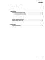
1. Presentation
Wheels position
Dimensions (H x W x D)
MX Frame
688x445x738 mm
15 000 RT/ 20 000 RT 27 x 18 x 29 inches
(on wheels)
Weights
MX Frame
71 kg
157 lbs
MX Frame
15 000 RT
194 kg
428 lbs
MX Frame
20 000 RT
239 kg
527 lbs
Rack position
Dimensions (H x W x D)
MX Frame
688x445x738 mm
15 000 RT/ 20 000 RT 27 x 18 x 29 inches
(wheels removed)
Sub-modules
Weights
34008486EN/AC - Page 8
MX Frame
Power sub-module
12 kg
26 lbs
MX Frame
Battery sub-module
30 kg
65 lbs
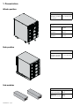
1. Presentation
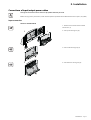
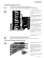
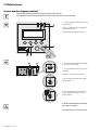
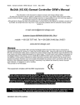
Rear panels
MX Frame 15000 RT / 20000 RT
1
11
12
2
13
14
3
15
16
17
4
18
5
19
6
7
8
(1) Normal AC source input switch
(2) Single phase or three-phase input
selection
(3) Residual-current earth-leakage circuit
breaker 30mA for PDU1 and PDU2
(4) Groups of 2 (10A) outlets for
connection of equipment
(5) Groups of 2 (16A) outlets for
connection of equipment
(6) 10A thermal switch
(7) 15A thermal switch
(8) Normal AC source terminal block
(9) Bypass AC source terminal block
(10) Output terminal block
(11) Slot for optional communication card
(12) Manual Bypass switch
(13) Remote Power Off communication
port (RPO).
(14) Communication port by relay
(15) USB communication port
(16) RS232 communication port
(17) Two groups of 2 programmable (10A)
outlets for connection of equipment
(18) Connector for automatic detection of
battery module(s)
(19) Connector for additional battery
module
9
10
34008486EN/AC - Page 9
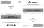
1. Presentation
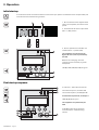
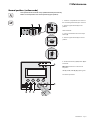
Display and control panel
1
2
3
a
4
b
c
d
5
ESC
6
7
8
11
I
12
O
9
13
14
(1) Load protected LED
(2) Downgraded operation LED
(3) Load not protected LED
(4) Alphanumeric display
(a) Upper line exists, access by (6)
(b) Lower menu exists, access by (8)
(c) Active line
(d) Lower line exists, access by (5)
(5) (6) Function buttons (scroll down /
scroll up)
(7) Escape (cancel) button
(8) Enter (confirm) button
(9) UPS OFF button
(10) UPS ON button
(11) Rectifier LED
(12) Battery LED
(13) Inverter LED
(14) Bypass LED
(15) Load powered LED
10
15
Sub-module pictograms on display
(1) Sub-modules detection
(
(2) The power sub-module and the battery
sub-module are not detected on the level
(MX Frame 15000 RT)
(3) Internal battery sub-module fault
detected
(4) Internal power sub-module fault
detected
For internal sub-module fault description,
see section 5.2, page 35
34008486EN/AC - Page 10
1. Presentation
Battery extension
MX Frame offers a standard backup time of 5 minutes at full load.
To increase backup time up to 62 minutes (at full load), it is possible to connect MX EXB RT modules to the UPSs.
Battery extensions for MX Frame
MX EXB RT (optional battery module)
1
BATT. NO.
BATTERY
CONNECTOR
180Vdc
BATTERY
CONNECTOR
180Vdc
2
BATTERY BREAKER 50Adc
3
3
(1) Connectors for automatic detection of
battery module(s)
(2) Battery circuit breaker
(3) Connectors for battery modules (to the
UPS or to the other battery modules)
Battery Integration System
The Battery Integration System is
intended for extended backup time
configurations to conveniently stack and
secure up to 8 modules on the same cart
(swivel wheels with brakes, leveling feet,
seismic side panels, plates to lock
modules and screws included).
Battery extension cable (1,8 m / 6 ft)
This extended battery cable will be used instead of the standard battery cable when battery modules are distant from
each other (located in two different enclosures, for instance).
34008486EN/AC - Page 11
2. Installation
Unpacking and contents check
Unpacking
Keep the packaging parts for wheels removal.
(
Contents check
(1) MX FRAME 15 000 RT or 20 000 RT UPS.
(7) 4 cable lockers.
(2) Solution-Pac power management suite CD-ROM.
(8) 8 IEC 10A output cables.
(3) Product documentation.
(9) Network Management card
(4) Rack mounting kit
(10) 3 or 4 Battery sub-modules (3 for 15 000 RT, 4 for 20 000
RT)
(5) Screw driver.
(6) RS232 communications cable
(11) 3 or 4 Power sub-modules (3 for 15 000 RT, 4 for 20 000
RT)
Packaging must be destroyed according to waste management standards. Recycling icons are displayed for easy
selection.
A dangerous voltage is present inside the power module and the battery module. Any operations to be carried out
on these modules must be done so by qualified staff.
34008486EN/AC - Page 12
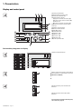
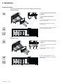
2. Installation
Rack mounting
Wheels removal
The battery sub-modules and power sub-modules must no be mounted yet.
It is not allowed to install the UPS or battery module in a hermetically closed environment without any exchange of
air.
1 - Use packaging as shown.
2 - Place MX Frame on its side.
3 - Remove the 4 screws of the 4 wheels.
4 - Remove the feet
Rack mounting kit
Rack mounting kit content (19" enclosure)
1
2
(1) Telescopic rails, 639 mm to 1005 mm
length (27.36’’ to 39.96’’)
(2) Front mouting brackets
34008486EN/AC - Page 13
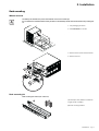
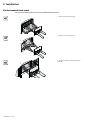
2. Installation
UPS module rack mounting
The battery sub-modules and power sub-modules must no be mounted yet.
It is not allowed to install the UPS or battery module in a hermetically closed environment without any exchange of
air.
Follow steps 1 to 4 for rack mounting the UPS onto the rails.
The rails and the necessary mounting hardware are supplied by EATON.
Note for step 1: it is possible to adjust the position of both front mounting ears.
34008486EN/AC - Page 14
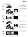
2. Installation
Mounting sub-modules
A dangerous voltage is present inside the power module and the battery module. Any operations to be carried out
on these modules must be done by qualified staff.
You must mount the modules from the lowest level to the highest level.
All the sub-modules must be mounted.
Always keep 150 mm free space behind
the UPS rear panel.
1 - Remove the 6 fixing screws to free the
front panel as shown.
Modules must be mounted from the
lowest level (1) to the highest level (4).
2 - Remove the 4 fixing screws of the
mounting screws to free the power submodule space.
Repeat the operation 2 for the battery submodule space.
3 - Insert the power sub-module and attach
the 4 mounting screws on each side of the
power sub-module.
Caution! the battery is heavy:
approx. 30 kg/65 lbs
4 - Insert the battery sub-module and
attach the 4 mounting screws on each side
of the battery sub-module.
5 - Reattach the front panel.
◗ Caution:
a battery can cause electrocution and high short circuit currents.
Do not dispose of batteries in a fire. The battery may explode
Do no open or mutilate batteries. Released electrolyte is harmful to the skin and eyes. It may be toxic.
34008486EN/AC - Page 15
2. Installation
Communication ports
MX RT provides 3 communication methods that can be used simultaneously:
◗ 2 COM ports provide RS232 or USB communications using EATON SHUT protocol. Compatible with most power
management software applications available into the enclosed Solution Pac CD-Rom. Please, note that both ports
cannot be used at the same time.
◗ The output contact port is used for basic signaling or for protection of IT systems like IBM iSeries (formerly AS400)
and more.
◗ The two slots are compatible with any EATON communication card (check www.eaton.com web site for the
complete list of compatible cards).
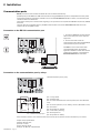
Connection to the RS 232 communication port
1 - Connect the RS232 (1) communications
cable to the serial port on the computer
equipment.
2 - Connect the other end of the
communication cable (1) to the RS232 (2)
communications port on the UPS.
The UPS can now communicate with
various EATON power management
application software. Please note that the
configuration software is included with
Personal Solution Pac for Windows.
2
1
Connection to the communication port by relays
(1) Communication port by relay
1
5
4
9
3
8
2
7
1
6
◗ Pin
1: major alarm
◗ Pin
2: battery fault
◗ Pin
3: remote shutdown from external power (5 to 27 V DC/10 mA
max).
◗ Pin
n.o.
n.o.
n.o.
n.o.
n.o. n.o.
n.o.
common
n.o. : contact normally open
4: normal operation, not on battery, contact ( 48 V DC/2 A max)
◗ Pin
5: common
◗ Pin
6: operation on bypass,
◗ Pin
7: low battery warning
◗ Pin
8: load powered
◗ Pin
9: operation on battery
When the status is active, the contact between the common (Pin 5) and the relevant information pin is closed.
Output relays specifications
48 V DC max,
◗ Current: 2 A max,
◗ Power: 62.5 VA, 30 W.
Example: for 48 V DC, Imax=625 mA
◗ Voltage:
34008486EN/AC - Page 16
2. Installation
Installation of communication card
It is not necessary to shutdown the UPS
before installing a communications card.
100
Reset
10
100
Reset
1 2
ON
IP=
MAC=00E0D8FF855E
2
RS232 Download
ETHERNET
UPS
data
RS232
Card Settings
66074
1 2
ON
IP=
MAC=00E0D8FF855E
1 - Remove the slot cover (1) secured by
two screws.
2 - Insert the communication card (2) in the
slot.
3 - Secure the card with both screws.
RS232 Download
10
ETHERNET
UPS
data
RS232
Card Settings
66074
1
Remote Power Off communication port
(1) Remote Power Off communication port (RPO).
1
Installation of a Remote Power Off function must be carried out in compliance with applicable regulations.
In order to fully de-energize devices and MX Frame with the RPO port, it is necessary:
◗ to use a two-position switch (Normally Open or Closed contact should be held more than 1 second to be taken into
account).
(1) and downstream(2) MX
◗ to connect to this RPO switch a device that allows to trip all breaker(s) located upstream
RT. This can be achieved by means of a shunt trip.
(1) : If not, the output devices could be powered again through static switch when the two-position switch is released.
(2) : If not, the output devices will remain powered several seconds after the RPO activation.
Please, notice that the internal batteries will remain connected to the power sub-module after RPO activation.
The cable is not included.
Remote power off contact normally open
RJ12 (6p6c)
Remote power off contact normally closed
RJ12 (6p6c)
654321
654321
5 V DC to 27 V DC
5 V DC to 27 V DC
◗ Signal:
- activation voltage: 5 V DC to 27 V DC.
- current: 10 mA max.
34008486EN/AC - Page 17
2. Installation
Required protective devices and cable cross-sections
Recommended upstream protection
UPS power rating
Upstream circuit breaker
15000/20000 RT
D curve - 125 A
The indicated protection ensures
discrimination for each output circuit
downstream of the UPS.
If these recommendations are not
followed, protection discrimination is not
achieved and may result in a potential
power interruption to the connected
devices.
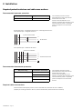
Single phase input : To UPS Normal AC source and/or Bypass AC source
Three phases input : To Bypass AC source
2 poles circuit breaker
L1
N
G
N
To AC source
L
Three phases input : To Normal AC source
4 poles circuit breaker
2 poles circuit breaker
L1
L2
L3
To Normal AC source
N
G
N
L3 L2
L1
Recommended downstream protection
UPS power rating
Downstream circuit breaker
15000 RT
Z curve - 10A
C curve - 6A
20000 RT
Z curve - 10A
C curve - 6A
The indicated protection ensures
discrimination for each output circuit
downstream of the UPS.
If these recommendations are not
followed, protection discrimination is not
achieved and may result in a potential
power interruption to the connected
devices.
Required cable cross-sections
◗ Terminal-block
◗ Capacity
34008486EN/AC - Page 18
cable capacity: 25 mm², solid or stranded wire (maximum 25 mm² or AWG 2).
for earthing conductor: 25 mm², solid or stranded wire (maximum 25 mm² or AWG 2).
2. Installation
Installation depending on the system earthing arrangement (SEA)
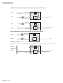
Single phase input
UPS with common Normal and Bypass AC inputs
Main lowvoltage
switchboard
(MLVS)
Bypass AC
load
Normal AC
Change in SEA between upstream and downstream or galvanic isolation required
Bypass AC
Main lowvoltage
switchboard
(MLVS)
load
Normal AC
UPS with separate Normal and Bypass AC inputs
Main lowvoltage
switchboard
(MLVS)
Bypass AC
*
load
Normal AC
Change in SEA between upstream and downstream or galvanic isolation required
Main lowvoltage
switchboard
(MLVS)
Bypass AC
*
load
Normal AC
* The transformer is not necessary if:
Normal and Bypass AC inputs are connected to the same source,
and wires cross sections and wires lengths on Normal and Bypass inputs are identical,
and upstream protection is provided by only one switch with RCD (residual current device) for Normal and Bypass
inputs.
34008486EN/AC - Page 19
2. Installation
UPS with separate Normal and Bypass AC inputs, supplied by separate sources
MLVS 1
Bypass AC
load
MLVS 2
Normal AC
Bypass AC
MLVS 1
MLVS 2
load
Normal AC
Change in SEA between upstream and downstream or galvanic isolation required
MLVS 1
Bypass AC
11
MLVS 2
10
8
load
Normal AC
Frequency converter (without Bypass AC input)
Configuration used when the frequency of the application differs from the Mains (Example : marine requirements).
Main lowvoltage
switchboard
(MLVS)
load
Normal AC
34008486EN/AC - Page 20
2. Installation
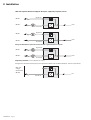
Three phases input
MX Frame must be fed from a 3-phase source with neutral.
UPS with common Normal and Bypass AC inputs
Main lowvoltage
switchboard
(MLVS)
Bypass AC
load
Normal AC
Change in SEA between upstream and downstream or galvanic isolation required
Bypass AC
Main lowvoltage
switchboard
(MLVS)
load
Normal AC
UPS with separate Normal and Bypass AC inputs
Main lowvoltage
switchboard
(MLVS)
Bypass AC
*
load
Normal AC
Change in SEA between upstream and downstream or galvanic isolation required
Main lowvoltage
switchboard
(MLVS)
Bypass AC
*
load
Normal AC
* The transformer is not necessary if:
Normal and Bypass AC inputs are connected to the same source,
and wires cross sections and wires lengths on Normal and Bypass inputs are identical,
and upstream protection is provided by only one switch with RCD (residual current device) for Normal and Bypass
inputs.
34008486EN/AC - Page 21
2. Installation
UPS with separate Normal and Bypass AC inputs, supplied by separate sources
MLVS 1
Bypass AC
load
MLVS 2
Normal AC
Bypass AC
MLVS 1
MLVS 2
load
Normal AC
Change in SEA between upstream and downstream or galvanic isolation required
MLVS 1
Bypass AC
load
MLVS 2
Normal AC
Frequency converter (without Bypass AC input)
Configuration used when the frequency of the application differs from the Mains (Example : marine requirements).
Main lowvoltage
switchboard
(MLVS)
loa
Normal AC
34008486EN/AC - Page 22
2. Installation
Connections of input/output power cables
This type of connection must be carried out by qualified electrical personnel
Before carrying out any connection, check that the upstream protection device Normal AC source is open ("O") (OFF)
Input connection
Access to terminal block
1 - Remove the 2 screws of the terminal
block cover (1).
2 - Pull up the moving tray (2).
1
2
2
1
3 - Pull out the moving tray (2).
3
2
4
4 - Pull down the moving tray (2).
2
34008486EN/AC - Page 23
2. Installation
Single phase input
This type of connection must be carried out by qualified electrical personnel
Common sources
1
1 - Be sure that the one-phase metal strap
is installed
2
2 - Be sure that the metal jumper is
installed
3
4
3 - Connect the 3 cables to the normal AC
source terminal block
4 - Connect the 3 cables to the output
terminal block
5 - Be sure that input selection selector (1)
is set to single phase position.
1
Separate sources
1 - Be sure that the one-phase metal strap
is installed
2 - Connect the 3 cables to the normal AC
terminal block
1
1
34008486EN/AC - Page 24
2
3
3 - Connect the 3 cables to the output
terminal block
4 - Be sure that single phase or threephase switch selection (1) is set to single
phase position.
2. Installation
Three phases input
This type of connection must be carried out by qualified electrical personnel
Common sources
1 - Remove the one-phase metal strap (1)
1
2 - Be sure that the metal jumper (2) is
installed
2
3 - Connect the 5 cables to the normal AC
source terminal block
4 - Connect the 3 cables to the output
terminal block
2
3
4
5 - Remove cover and put input selection
selector (3) to three phase position.
3
Separate sources
1 - Remove the one-phase metal strap (1)
1
2 - Remove the metal jumper (2)
2
3 - Connect the 5 cables to the normal AC
source terminal block
4 - Connect the 3 cables to the bypass AC
source terminal block
1
3
2
3
5 - Connect the 3 cables to the output
terminal block
5 - Remove cover and put single phase or
three-phase switch selection (3) to threephase position.
34008486EN/AC - Page 25
2. Installation
Fix the terminal block cover
This type of connection must be carried out by qualified electrical personnel
1 - Push up the moving tray (1).
1
1
2 - Push in the moving tray (1).
2
1
3 - Fix the 2 screws of the terminal block
cover (2).
3
2
34008486EN/AC - Page 26
2. Installation
Extended battery (EXB) connections
This type of connection must be carried out by qualified electrical personnel
It is not necessary to shutdown the UPS in order to install the extended battery (EXB) module.
Up to three batteries may be connected to each levels of the MX Frame.
The sequence below shows connection for two battery cabinets per level on a MX Frame 20000 RT model.
1 - Check that the battery circuit breaker (1)
of each EXB is OFF ("0" position).
Start the following operations from the
lowest level:
2 - Connect the battery cable (2) to the UPS
battery power connector (3) and the other
end of the battery cable to the EXB battery
power connector (4).
3 - Connect the battery detection cable (5)
to the UPS battery detection connector (6)
and the other end of the battery detection
cable to the EXB battery detection
connector (7).
4 - Connect the inter-EXB battery cable (8)
to the second EXB battery power
connector (9) and the other end of the
battery cable to the second EXB battery
power connector (10) of the above EXB.
12 10 9
8
11
7
5
1
4
2
6
5 - Connect the battery detection cable to
the second EXB battery detection
connector (11) and the other end of the
battery detection cable to the second EXB
battery detection connector (12) of the
above EXB.
3
6 - Repeat operations 2 to 5 to other levels
7 - Close the battery circuit breaker (1) of
each EXB ("I" position).
Caution: a battery can cause electrocution and high short circuit currents.
Do not dispose of batteries in a fire. The battery may explode
Do no open or mutilate batteries. Released electrolyte is harmful to the skin and eyes. It may be toxic.
Connection of IEC cables to output receptacles
3
2
4
1
5
1 - Connect the equipments to the UPS
using the cables (1).
It is preferable to connect the priority
equipments to the two outlets (3) and the
non priority equipments to the two outlets
(2) that can be programmed in pairs.
Connect any high-power devices to the
16 A outlet (4).
To program shutdown of outlets (2) during
operation on battery power and thus
optimise the available backup time, the
EATON communication software is
required.
2 - Fit the connection securing system (5)
that prevents the plugs from being pulled
out accidentally.
34008486EN/AC - Page 27
3. Operation
Initial start-up
It is essential to contact our Customer Service to ensure that your system is commissionned in complete safety and
to benefit from the manufacturer’s guarantee.
1
1 - Be sure that the manual bypass switch
(1) is in normal position, like shown on the
picture.
2
2 - Put the Normal AC source input switch
(2) in "1" (ON) position
3 - Set the upstream circuit breaker (not
included) to the "I" position (ON).
3
The equipments are powered via the
Bypass AC source, but not protected by
the UPS.
Batteries are recharging, an 8 hour
recharge period is necessary to get full
backup time.
ESC
LED (3) is ON, LEDs (4) and (5) are green.
I
O
4
5
Final start-up sequence
2
6
7
3- Press the "I" button (1) more than 3s.
The buzzer beeps once, and after UPS
internal test sequence, the LED (2) is ON.
If internal test sequence fail, see chapter 7
LEDs (3), (4), (5) are green.
The equipments are protected by the
UPS.
ESC
3
4
5
34008486EN/AC - Page 28
I
If LED (6) or (7) is ON, an alarm has
occurred (see the "troubleshooting"
section).
O
1
3. Operation
Operating modes
Normal mode
1
ESC
2
I
O
3
4
This is the standard operating mode, set
by default in the factory.
Under normal condition (Normal AC
source available):
LED (1) is ON.
LEDs (2), (3), (4) are green.
The equipments are protected by the
UPS.
Battery mode
When the Normal AC source is not available, the load continues to be protected by the UPS.
Power is supplied by the battery.
Transfer to battery power
1
2
LEDs (1), (2) are ON.
LEDs (3), (4), (5) are green.
The audio alarm beeps every 10 seconds.
ESC
3
I
O
4
5
The equipments are protected by the UPS
and supplied by the battery.
The display indicates the battery
remaining backup time.
Low battery warning
1
2
LEDs (1), (2) are ON.
LEDs (3), (4), (5) are green.
The audio alarm beeps every 3 seconds.
ESC
3
I
O
4
5
The remaining battery power is low.
Shut down all applications on the
connected equipment because automatic
UPS shutdown is imminent.
End of backup time
1
LED (1) is ON.
LED (2) is red.
The audio alarm beeps continuously.
ESC
The equipments are not powered.
I
O
2
The UPS displays "End of backup time
Battery low".
Return on Normal AC source
After an outage, the UPS restarts automatically when Normal AC source is restored (unless this function has been
disabled via UPS personalisation) and the load is supplied again.
34008486EN/AC - Page 29
3. Operation
UPS shutdown
1 - Press the "0" button (1) more than 3s.
The buzzer beeps once, and the load is no
longer protected by the UPS. It is powered
via the Bypass AC source. If the UPS is set
in frequency converter mode, the
equipments will not be powered.
If the Normal AC source is out of
tolerance, the UPS will generate a 10ms
output calibrated break.
ESC
I
O
1
34008486EN/AC - Page 30
2 - For a full shutdown of UPS and
connected load, the upstream circuit
breaker (not included) should be set to the
"0" position.
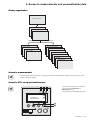
4. Access to measurements and personalisation data
Display organisation
Status and Alarms
Measurements
UPS input measurements
UPS output measurements
Battery measurements
Maintenance
UPS Set-up
Local settings
Model
Measures (per module)
Output settings
Alarm History
ON/OFF settings
System diagnosis
Battery settings
Manual batt test
Led & Buzzer test
LCM
Statistics
Operation limits
Access to measurements
Press the scroll button (see section 1.5, page 10) to access measurements for voltage, current, frequency, power
output and battery capacity.
Access to UPS set-up and maintenance
◗ Press the scroll button (1) a number of
times to point the UPS set-up or
Maintenance menu
◗ Press the Enter button (2) to get access.
UPS SET-UP
MAINTENANCE
ESC
1
2
I
O
34008486EN/AC - Page 31
4. Access to measurements and personalisation data
UPS set-up
Local settings
Function
Factory setting
Options
Language
English
French, German, Italian, Portuguese, Spanish
Date / Time Format
International
US (MM-DD-YYYY/HH:MM AM/PM)
(DD-MM-YYYY/HH :MM)
Date / Time Change
GMT + 1
(Continental Europe)
MM-DD-YYYY/HH :MM adjustable
Audible Alarm
Yes
No
Output settings
Function
Factory setting
Options
Comments
Output Voltage
230 V
200 V / 208 V / 220 V /
240 V / 250 V
Freq Converter
Disable
Enable
Output Frequency
50 Hz
60 Hz
User selectable under frequencyconverter mode
Bypass Transfer
Yes
No
Transfer to bypass if Normal AC
source is out of tolerance
Interrupt Time
10 ms
20 ms, ...... , 200 ms
Break time calibration during load
transfer on Normal AC source out
of tolerance
Overload Prealarm
105 %
40 %, 50 %, 70 %
Alarm if threshold is overrun
Redundancy Mode
No
Yes
Alarm if redundancy loss
Redundancy Level
1
2,3
On redundancy Mode:number of
redundant modules needed
ON/OFF settings
Function
34008486EN/AC - Page 32
Factory setting
Options
Comments
Cold Start
Disable
Enable
Start on battery
Forced Reboot
Enable
Disable
Enables automatic restart of the
system even if Normal AC source is
restored before the end of the
shutdown sequence
Auto Restart
Enable
Disable
UPS restarts automatically when
Normal AC source is restored
Energy Saving
Disable
Enable
Automatic shutdown on battery if
output load level < 10 %
Sleep Mode
Enable
Disable
Remote Command
Enable
Disable
Enables consideration of shutdown
or restart orders from software to
be authorised
4. Access to measurements and personalisation data
Battery settings
Function
Factory setting
Options
Comments
Auto Battery Test
Everyweek
No test / everyday /
everyweek /everymonth
Low Batt Warning
20%
0 to 100%
1% increment
User Batt Settings
UPS reads number of
battery modules
connected
From 0 to 40 Ah
5 Ah increment
Deep Disch Protect
Yes
No
Protection against deep discharge.
If disable, EATON warranty will be
void
Maintenance
Function
Model
Sub-Function
Power Module
Frame
Option / Display
SN: xxxxxxxxx
SOFT: xxx
NT: xxx
Measurement
Monitoring by selecting
modules 1 trough 4
Status for each module:
Input/Output
kVA to load Battery
capacity
Alarm History
Read
Description
Date Hour
Alarm xxx
Erase
No / Yes
System Diagnosis
Module detection
Status for each module
Manual Batt Test
Manual Battery Test
No / Yes
Led & Buzzer Test
Led & Buzzer Test
No / Yes
Life Cycle Monitoring
LCM
Enable / Disable
Statistics
Auto Statistics
Statistics
Custom Statistics
Reset Date ?
Are you sure ?
Operation Limits
Operation Limits
Comments
Serial number
Soft version
Technical level
10 alarms can be stored
automatically
Life cycling monitoring alarms
Automatic alarms displayed when
UPS is operating near the limits
Personalisation using external software
Insert the Solution-Pac CD-ROM in the drive.
On the first navigation screen, select "Point to Point solution" and follow the instructions on how to install the
Personal Solution-Pac software.
◗ Then select "Settings", "Advanced settings" and "UPS settings".
Note that only the Windows versions of the Personal Solution-Pac software offer this possibility.
◗
◗
34008486EN/AC - Page 33
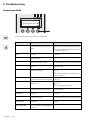
5. Troubleshooting
Troubleshooting LEDs
If LED (1) is ON:
the equipments are protected by the UPS
but the operation is downgraded.
1
If LED (2) is ON:
the equipments are no longer protected
by the UPS.
2
Press the escape button (3) to stop the
audible alarm.
x.xkVA / xxx% LOADED
x x x x x x x x FAULT
SINGLE UPS
3
ESC
4
I
O
5
Note :
In case of "MULTIPLE FAULT", press the
"Enter" button (4) and the scroll button (5)
to get access to further details.
In case of "LCM WARNING", refer to LCM
section (see section 6, page 38).
if LED (6) is ON:
The equipments are no longer supplied.
ESC
Follow the displayed instructions.
I
O
6
if one of the following LEDs is ON
ESC
7
I
O
8
9
10
34008486EN/AC - Page 34
Rectifier LED (7)
Inverter LED (8)
Battery LED (9)
Bypass LED (10)
One of the main UPS function has faulted.
Follow the displayed instructions.
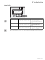
5. Troubleshooting
System diagnosis fault
A internal sub-module fault is detected
..
A internal power sub-module (1) fault is
detected.
SYSTEM DIAGNOSIS
FAULT
!
START
1
OPTIONS
ESC
Press the "Enter" button (2).
2
I
Choose one of the two sequences below:
O
Start with xUPS
You can even run the UPS with a reduced power rate
Press the scroll button (3).
Press the "Enter" button (4).
START
OPTIONS
N O START
S T A R T W I T H xUPS
ESC
3
4
I
O
Check power or battery sub-module connections (see section 7, page 39).
If the connections are correct, call the after-sales support department and follow the sub-module replacement
procedure (see section 7, page 39).
No start
Press the "Enter" button (4).
START
OPTIONS
N O START
S T A R T W I T H xUPS
ESC
4
Check power or battery sub-module connections (see section 7, page 39).
If the connections are correct, call the after-sales support department and follow the sub-module replacement
procedure (see section 7, page 39).
34008486EN/AC - Page 35
5. Troubleshooting
Environment faults
LOAD PROTECTED
x.xkVA / xxx% LOADED
ENVIRONMENT FAULT
SINGLE UPS
ESC
1
Press the "Enter" button (1) to display the details below :
Displayed details
= BATTERY Ah
34008486EN/AC - Page 36
Signification
The number of detected batteries of a
level is low compared to the other
levels.
Correction
Check the external battery connection (detection
cable and power cable) see section 2.3 page 27
Or
Put the same number of EXB for each level, see
see section 2.3 page 27
BYPASS AC FREQ/VOLT The Bypass AC source is out of
NOK
tolerance.
Check the Bypass AC source voltage or
frequency.
I/O BAD CONNECTION
AC source is not connected to the
correct terminals
Check AC wiring, see section 2.1 page 23
INV THERM OVERLOAD
The UPS shuts down automatically
because of a major overload.
Check the power drawn by the connected
devices and disconnect any non-priority devices.
INVERT LIMITATION
Short circuit conditions on output
devices
Check the installation at the UPS output (wiring,
fault equipment).
NO BATTERY
The battery is incorrectly connected, or Check battery connections, see section 2.3
no battery is detected.
page 27
Or
Insert the missing batteries sub-modules, see
section 1.9 page 15
NO BATTERY MODULE
No battery sub-module is detected
Check battery sub-module connections, see
next to an inserted power sub-module. section 7.2
NO MODULE
No module is detected on the first
(lowest) level.
NO POWER MODULE
No power sub-module is detected next Check power sub-module connections, see
to an inserted battery sub-module.
section 1.9 page 15
NORMAL AC FREQ/
VOLT NOK
The Normal AC source is out of
tolerance
Check the Normal AC source voltage or
frequency.
OUTPUT OVERLOAD
The UPS is on overload and will shut
down automatically
Check the power drawn by the connected
devices and disconnect any non-priority devices.
POWER MODULE NOT
COMPATIBLE
The power sub-module inserted is not Check if the power rate of the power sub-module
compatible.
is 5 kVA.
SOFT FRAME POWER
NOT COMPATIBLE
The software of the power sub-module Upgrade the UPS software via www.eaton.com
is not compatible with the Mx Frame
software
Check the module detection, see section 1.9
page 15
Or
Insert the missing sub-modules.
5. Troubleshooting
Internal faults
LOAD PROTECTED
x.xkVA / xxx% LOADED
x x x x x x x x FAULT
SINGLE UPS
ESC
1
2
Display
Signification
Correction
POWER MODULE FAULT
Internal power sub-module fault detected.
Use "Enter" button (1) to display details.
Call the after-sales support department.
Follow the power sub-module
replacement procedure (see section 7.1
page 39)
BATT MODULE FAULT
Battery fault detected during the battery
test.
Use "Enter" button (1) to display details.
Call the after-sales support department.
Follow the battery sub-module
replacement procedure (see section 7.2
page 39)
FRAME FAULT
Internal chassis fault detected.
Use"Enter" button (1) to display details.
Call the after-sales support department.
Follow the frame replacement procedure
(see sections 7.1, 7.2 page 39)
Note: In case of multiple fault, press the "Enter" button (1) and the scroll buttons (2) to get access to further details.
34008486EN/AC - Page 37
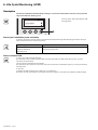
6. Life Cycle Monitoring (LCM)
Description
This function, embedded in the UPS, displays messages, on screen and communication channels, at every important
stage of the UPS’s life, allowing you to:
Press the "Enter" button (1) to display LCM
warning details.
LOAD PROTECTED
x.xkVA / xxx% LOADED
LCM WARNING
SINGLE UPS
ESC
1
I
O
Secure your installation power continuity
Anticipate maintenance actions thanks to automatically displayed warnings while displaying automatic warnings
when maintenance actions need to be planned :
LCM warning details
BATTERY CHECK RECOMMENDED
CONTACT EATON AT
www.eaton.com
Signification
Battery is approaching its reliability end of life. Risk to reduce
dramatically backup time
Reset or disable LCM
In case of any LCM messages displayed:
◗ For temporary reset: press the escape button more than 3 seconds, into Status and Alarm screen, to cancel
temporary the alarm status.
The alert will be repeated twice each 30 days.
◗ For permanent reset: press the enter button more than 3 seconds, into LCM warning screen, to cancel permanently
this LCM event.
At any time:
To Disable all LCM messages select "disable all" ,into LCM menu.
Be careful: you will not be aware of any LCM events that can happen on the UPS if you disable all LCM messages.
34008486EN/AC - Page 38
7. Maintenance
Hot swapping the power sub-module
This operation must be carried out by qualified electrical personnel only.
This operation can be performed without interrupting the equipments.
Disconnecting the power sub-module :
1 - Remove the 6 fixing screws to free the
main front panel bezel.
2 - Remove the 4 fixing screws on the left
side to free the power sub-module.
3 - Withdraw the power sub-module.
Reconnecting the power sub-module :
◗ Carry
out the above instructions in reverse order.
◗ Replace
the faulty power sub-module by another one with same power rating.
Hot swapping the battery sub-module
◗ Caution:
a battery can cause electrocution and high short circuit currents.
Do not dispose of batteries in a fire. The battery may explode
Do no open or mutilate batteries. Released electrolyte is harmful to the skin and eyes. It may be toxic.
◗Servicing
of batteries should be performed or supervised by personel knowledgeable of batteries and the required
precautions. Keep unauthorized personel away from batteries.
◗ Remove watches, rings, bracelets and all other metal objects from the hands and arms,
◗ Use tools with an insulated handle.
◗ When replacing batteries, replace with the same number of the BB/HR5.5-12 batteries.
This operation can be performed without interrupting the equipments.
Disconnecting the battery sub-module :
1 - Remove the 6 fixing screws to free the
main front panel bezel.
2 - Remove the 4 fixing screws on the right
side to free the battery sub-module.
3 - Pull the battery sub-module slightly,
then lift it to extract it.
Reconnecting the battery sub-module :
Carry out the above instructions in reverse order.
◗ To
ensure safety and high performance, use only batteries supplied by EATON.
34008486EN/AC - Page 39
7. Maintenance
Service position (bypass position)
This operation must be carried out by qualified electrical personnel only.
The equipments should be powered via the Normal AC source, and not protected by the UPS.
2
1 - Press and hold the (0) (OFF) button (1)
for 3 seconds/
The load is powered via the Bypass AC
source (bypass mode).
LED (2) is ON, LEds (3), (4) are green
ESC
I
3
O
1
4
5
6
NORMAL
2 - Unlock the Manual Bypass switch (5)
and set to the test position.
2
TEST
3
3 - Turn off the Normal AC source circuit
switch (6).
BYPASS
All LEDs on the front display are off.
NORMAL
4
TEST
4 - Set the Manual Bypass switch (5) to
bypass position.
BYPASS
NORMAL
5
TEST
5 - Pull red padlock in the center of the
manual bypass switch (5) to lock into
bypass position.
BYPASS
6 - Remove all the battery sub-modules,
see section 7.2, page 39.
The MX Frame is now ready for service.
34008486EN/AC - Page 40
7. Maintenance
Normal position (online mode)
This operation must be carried out by qualified electrical personnel only.
Return to normal position from service position (bypass position).
1 - Push the red padlock in the center of
the manual bypass switch (1) to unlock it
1
2
NORMAL
1
TEST
3
2 - Set the bypass switch (1) to test
position.
Wait 3 seconds.
BYPASS
3 - Turn on the Normal AC source input
switch (2).
NORMAL
2
TEST
4 - Set the bypass switch (1) to normal
position.
BYPASS
NORMAL
4
TEST
BYPASS
4
5 - Press and hold the (I) (ON) button (3) for
3 seconds.
MX Frame performs an internal test
sequence.
LED (4) is ON, LEDs (5), (6), (7) are green.
The load is protected
ESC
I
5
6
O
3
7
34008486EN/AC - Page 41
7. Maintenance
Training centre
To fully master operation of your EATON product and carry out level 1 servicing, see our complete range of technical
training courses, available in both French and English.
For further information, please visit our website: www.eaton.com
34008486EN/AC - Page 42
8. Appendices
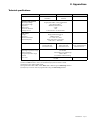
Technical specifications
MX Frame 15000 RT
Output power
Electrical supply network
input voltage
◗ Input voltage range
◗ Frequency
◗ Power factor
Harmonic distortion
◗ Leakage current
◗ Rated
Load output
◗ Voltage
◗ Frequency
◗ Harmonic
◗ Overload
distortion
capacity
Battery
Environment
temperature range
◗ Relative humidity
◗ Storage temperature range
◗ Altitude
◗ Operating
◗ Noise
level
MX Frame 20000 RT
(1)
MX EXB
(1)
/
15 kVA
13.5 kW (2)
20 kVA
/
18 kW (2)
Single phase 230 V / Three phase 400 V
120 / 156 V to 280 V (3)
50/60 Hz (autoselection)
> 0,99
> 5%
1:1 20 mA max. / 3:1 30 mA max.
Single phase 230 V ±3% (4)
50/60 Hz ±0,5% (5)
1:1 < 10% / 3:1 < 20%
105% continuous, 110% 2min,
125% 1min, > 150% 0.5s
15 x 12V - 5 Ah,
sealed lead acid,
maintenance free
15 x 12V - 5 Ah,
sealed lead acid,
maintenance free
Two 15 x 12 V - 5 Ah
strings, sealed lead acid,
maintenance free
0°C to 40°C
20% to 90% (non-condensing)
-25°C to 40°C
0 to 1000 m without derating
< 51 dBA
(1) If the output voltage is 200V - 250V, the output power is 15 kVA / 12 kW.
(2) With one EXB module or more, the standard output power is 20 kVA / 16 kW.
(3) Values for 70% / 100% of UPS output.
(4) Programmable: 200V / 208V / 220V / 230V / 240V / 250V using the UPS Config software.
(5) Frequency-converter mode is programmable using the UPS Config software.
34008486EN/AC - Page 43
8. Appendices
Glossary
34008486EN/AC - Page 44
Backup time
Time that the connected equipments can operate on battery power.
Bypass AC source
Source supplying the bypass line. The equipments can be transferred to the bypass line if
an overload occurs on the UPS output, for maintenance or in the event of a malfunction.
Equipments
Devices or systems connected to the UPS output.
Frequency converter
Operating mode used to convert the AC-power frequency between the UPS input and
output (50 Hz -> 60 Hz or 60 Hz -> 50 Hz).
Low-battery
warning
This is a battery-voltage level indicating that battery power is low and that the user must
take action in light of the imminent break in the supply of power to the load.
Manual bypass
Rotary switch controlled by the user, used to connect the equipments directly to the AC
source. Transfer of the equipments to the manual bypass enables UPS maintenance
without interrupting the supply of power to the connected equipments.
Normal AC source
Normal source of power for the UPS.
Normal (double
conversion) mode
The normal UPS operating mode in which the AC source supplies the UPS which in turn
supplies the connected equipments (after electronic double conversion).
Personalisation
It is possible to modify certain UPS parameters set in the factory. Certain UPS functions
can also be modified by the EATON power management products to better suit user needs.
Programmable
outlets
These outlets can be automatically shut down during operation on battery power
(shutdown time delays can be programmed with the EATON power management
products). The UPS has two sets of two programmable outlets.
Relay contacts
Contacts supplying information to the user in forme of signals.
UPS
Uninterruptible Power System.
Introduction
Nous vous remercions d’avoir choisi un produit EATON pour la sécurité de vos applications.
La gamme MX a été élaborée avec le plus grand soin.
Pour exploiter au mieux les performances de votre ASI (Alimentation Sans Interruption), nous vous conseillons de
prendre le temps de lire ce manuel
Attention : Cette ASI est un produit de classe A. Dans un environnement domestique, ce produit peut causer des
interférences radio, et dans ce cas, l’utilisateur pourra être amené à prendre des mesures complémentaires.
Les câbles de sortie ne doivent pas dépasser 10 m de longueur.
Si ce produit doit être installé dans un environnement de surtensions de catégorie III ou IV, une protection antisurtensions amont devra être prévue.
Avant l’installation de MX, lire le livret qui présente les consignes de sécurité à respecter. Suivre ensuite les
instructions du présent manuel.
Nous vous invitons à découvrir l’offre EATON ainsi que les options de la gamme MX en visitant notre site WEB :
www.eaton.com, ou en contactant votre représentant EATON.
Respect de l’environnement
La société EATON s’est engagée dans une politique de protection et de préservation de l’environnement.
Nos produits sont développés selon une démarche d’éco-conception.
Substances
Ce produit ne contient ni de CFC, ni de HCFC, ni d’amiante.
Emballage
Pour améliorer le traitement des déchets et faciliter le recyclage, séparer les éléments de l’emballage.
◗ Le carton est composé de plus de 50 % de carton recyclé.
◗ Les sacs et sachets sont en polyéthylène.
◗ Les matériaux constituant l’emballage sont recyclables et marqués du symbole d’identification
.
Matériaux
Abréviation
Numéro dans
le symbole
Polyéthylène Téraphthalate
PET
01
Polyéthylène Haute Densité
HDPE
02
Polyvinyle Chloride
PVC
03
Polyéthylène Basse Densité
LDPE
04
Polypropylène
PP
05
Polystyrène
PS
06
Suivre les réglementations locales en vigueur pour l’élimination de l’emballage.
Fin de vie
La société EATON s’est engagée à traiter les produits en fin de vie selon les réglementations locales.
EATON travaille avec des sociétés en charge de la collecte et de l’élimination de nos produits en fin de vie.
Produit
Le produit est composé de matériaux recyclables.
Son démantèlement et sa destruction doivent se faire en accord avec les réglementations locales en vigueur
concernant les déchets.
Le produit en fin de vie doit être déposé dans un centre de traitement des déchets électriques et électroniques.
◗
Batterie
Le produit contient des batteries au plomb qui doivent être traitées suivant les réglementations locales en vigueur
concernant les batteries.
Pour suivre ces réglementations et éliminer la batterie de manière propre, il est possible de l’extraire du produit.
◗
34008486FR/AC - Page 3
2. Installazione
Ingresso trifase
Questo tipo di collegamento deve essere effettuato da elettricisti qualificati
Alimentazioni comuni
1 - Rimuovere la piattina metallica
monofase (1)
1
2 - Accertarsi che il ponticello metallico (2)
sia installato
2
3 - Collegare i 5 cavi al blocco terminale
dell'alimentazione AC Normale
4 - Collegare i 3 fili al blocco terminale in
uscita
2
3
4
5 - Rimuovere il coperchio e posizionare il
selettore di ingresso (3) su trifase.
3
Alimentazioni separate
1 - Rimuovere la piattina metallica
monofase (1)
1
2 - Rimuovere il ponticello metallico (2)
2
3 - Collegare i 5 cavi al blocco terminale
dell'alimentazione AC Normale
4 - Collegare i 3 cavi al blocco terminale
dell'alimentazione AC Bypass
1
3
2
3
5 - Collegare i 3 fili al blocco terminale in
uscita
5 - Rimuovere il coperchio e posizionare il
selettore di commutazione monofase o
trifase (3) su trifase.
34008486IT/AC - Page 25