1
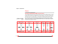
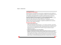
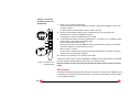
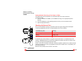
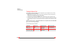
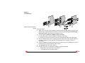
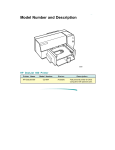
Product Manual Gigabit Ethernet Server Adapter (english) Gigabit Ethernet Server Adapter Product Manual English (v1.00 05-Sep-2000) Visit our web site: www.syskonnect.com First edition (September 2000). This edition refers to all current SysKonnect Gigabit Ethernet adapters. Contents are subject to change. Product and brand names are (registered) trademarks of their appropriate owners. Please, send your comments on this documentation to: SysKonnect / Information Development Siemensstraße 23 76275 Ettlingen Germany Fax: +49 7243 502 989 E-mail: [email protected] Copyright 2000 SysKonnect. All rights reserved Product Registration: The registration card for your SysKonnect product is contained in the "Register" directory on the CD ROM. (On the CD ROM start page, click button "Product Registration".) 2 Contents Contents 3 Chapter 1. Fundamentals 5 Features Redundant Link Management (RLMT) for Fault Tolerance 64-bit/66 MHz PCI Bus Interface Reduced Load on the CPU PCI Hot Plug Other Highlights Delivery Package Chapter 2. Connecting the Network Card to the Data Network Single Connection Dual Homing Chapter 3. Installing Protocol Drivers from the CD-ROM Installing Network Drivers (Protocol Drivers) Viewing Readme Files with an Internet Browser Viewing Readme Files Using a Text Viewer or Editor Checking the Network Port 6 6 7 7 8 8 9 10 10 12 14 14 14 15 15 3 Contents Chapter 4. Troubleshooting Answers to Frequently Asked Questions LED Displays Normal Status Meanings of the LEDs Testing the Network Card Loopback Test for SK-NET GE-T/SK-NET GE-T dual link If a Test fails... Checking Other Displays and Data 16 17 17 17 18 21 22 24 Appendix A. Technical Specifications 25 Appendix B. How to Identify Your Network Card Type 26 Appendix C. Electromagnetic Compatibility, EN 55022/FCC 27 Appendix D. Other Functions of the Diagnostics Program 28 Start the Main Program Reading Sensor Data Reading Configuration Data Reading VPD Data Sample Usage of VPD Data/Asset Tag Read/Write FPROM Data 4 16 28 29 29 30 31 32 Chapter 1. Fundamentals SK-NET Gigabit Ethernet Server Adapters combine servers and workstation computers with the highspeed Gigabit Ethernet network (1000 Mbit/s) using fiber-optic (FO) or copper cables. At present there are eight types available. They differ in terms of the number of ports and the transmission mode. SC duplex connectors, VF-45 connectors (FO) or RJ-45 connectors (copper cabling) are used to connect to the data network. The adapters can be connected to a switch, a buffered repeater, or directly to a second station (see also Fig. 1). Network card Port configuration SK-NET GE- Single-PortVersion Dual-PortVersion n Fiber-optic transmission (wavelength) Copper cabling 1300 nm UTP 850 nm n LX 9841 LX dual link 9842 SX 9843 n n SX Volition 9861 n n SX dual link 9844 n n SX dual link Volition 9862 n n T 9821 T dual link 9822 n n n n n n Computers in which the adapter is to be installed must have one free slot that complies at least with PCI specification v2.0. A 32-bit or a 64-bit PCI bus running at 33 or 66 MHz may be used. Optimum performance is generally obtained with a 64-bit/66 MHz PCI bus. 5 Chapter 1. Fundamentals Features For the SK-NET GE dual link types: Redundant Link Management (RLMT) for Fault Tolerance Figure 1. GE network configuration; connection options 6 The two Gigabit Ethernet ports offer dual homing similar to that found in FDDI technology. In order to provide greater fault tolerance the Gigabit Ethernet Server Adapter is connected to two switch ports. These ports may be on the same switch or on two switches in different physical locations. Only one port is active at any one time but both links are monitored. The second port is simply in standby mode. If the active link fails, the second port automatically takes over the connection. This means that the server connection is protected against the failure of a port on the switch, failure of a port on the network card and failure of a cable. Server: dual link dual link single link single link dual link single link Workstation: dual link single link single link single link dual link dual link Chapter 1. Fundamentals For all SK-NET GE types: 64-bit/66 MHz PCI Bus Interface Although designed as a 64-bit/66 MHz PCI bus interface, the Gigabit Ethernet Server Adapter can also be operated in 32-bit systems or at a clock frequency of 33 MHz. The cards operate as true Plug & Play adapters and automatically adjust to the different configuration options on the PCI bus. The high-speed 64-bit/66 MHz PCI bus is now state-of-the-art in high-end server systems. The theoretical bandwidth is four times greater than in conventional 32-bit/33 MHz systems. SysKonnect’s Gigabit Ethernet Server Adapters support this 64-bit/66 MHz PCI architecture, which means that the server network card cannot be a bottleneck on the system bus. Because of the wider data paths and the higher clock frequency, the Gigabit Ethernet Server Adapters reduces the bus and CPU utilization. For application and database servers in particular, this results in better application performance. Reduced Load on the CPU • • Support for Burst Data Transfer The PCI bus supports burst-mode data transfer, i.e. the continuous transmission of data blocks. This reduces the overhead for data transmission and is closely linked to the optimization of cache memory and the use of optimized data transfer commands between memory and the bus. The Gigabit Ethernet Server Adapter is therefore capable of using the maximum burst speed supported by the system. Dynamic Interrupt Moderation (PacedPacketBatch) Every time a data packet arrives via the network and is forwarded via the PCI bus, an interrupt is triggered in the host CPU. Each interrupt causes the system to halt its current processes and locate the origin of the interrupt. As a result, the system may branch to service routines, buffer the current register values and status and write these values back once the routine has terminated. If the network is running at gigabit speeds and small packets are being transferred, there may in extreme cases be more than 100,000 interrupts per second. To reduce the load on the CPU, the 7 Chapter 1. Fundamentals • Gigabit Ethernet Server Adapters can use interrupt moderation to group these interrupts so that several data packets can be handled per interrupt. Task Offload – Integrated Intelligent Functions Calculation of TCP, UDP, and IP checksums is CPU-intensive and is normally performed by the host CPU running the TCP/IP stack. These calculations are integrated in the hardware of the Gigabit Ethernet Server Adapters. The checksums are calculated without time loss in SysKonnect’s PCI Gigabit Ethernet ASIC for both the receive path and the transmit path. This improves the overall performance of the system and shifts these CPU-intensive tasks away from the host CPU. PCI Hot Plug As a member of the PCI Special Interest Group, SysKonnect participated in the standardization of the insertion and removal of PCI computer cards during normal server operation. Like all SysKonnect PCI cards, the Gigabit Ethernet Server Adapters comply with the Hot Plug PCI Standard. This technology increases the availability of the server(s) used. Other Highlights The following features make the Gigabit Ethernet Server Adapters particularly easy to operate, powerful and future-oriented: • Plug & Play compatible across the entire range • Network management capability • I2O-compatible • Class of service • VLAN • Parity monitoring on all data paths • Sensor-based monitoring of environment conditions (temperature/voltage) 8 Chapter 1. Fundamentals • • • Packet/fragment descriptors VPD support (Vital Product Data) APM support (Advanced Power Management) Delivery Package The delivery package includes the following: • the network card (FO types: including protective plugs), packed in an antistatic bag • the Installation CD-ROM • the manual SysKonnect Installation Guide • Release Notes, as appropriate • packaging material If any items are missing or damaged, please contact your dealer. 9 Chapter 2. Connecting the Network Card to the Data Network Notices: • You will find instructions for the mechanical installation of the adapter in your computer in the manual SysKonnect Installation Guide. • General instructions for driver installation are contained in Chapter 3 of this documentation. • Follow the handling and safety instructions given in the SysKonnect Installation Guide. The following table shows the transmission distances for which the different cables can be used: Type of network card Type of cable Port Type 62,5 µm Multimode 50 µm Multimode 10 µm Monomode UTP SK-NET GESX/SX dual link (Volition) 1000Base-SX 2...275 m 2...555 m - - LX/LX dual link 1000Base-LX 2...550 m 2...550 m 2...5000 m - T/T dual link 1000Base-T - - - 100 m The type of (optical) port on the network card and on the switch must be identical. The procedure for connecting the network card to the data network is as follows: Single Connection 1. If necessary, configure the port on the switch to which the network card is to be connected (see switch manual). 10 Chapter 2. Connecting the Network Card to the Data Network 2. Follow the safety instructions. If possible, disconnect the switch and the computer from the power supply. If you are hot plugging, you should also follow the safety instructions issued by the system vendor. 3. Remove the protective plug from the switch port which is to be used. 4. Connect the SC duplex, VF-45 or RJ-45 connector at one end of the cable to the port on the switch. 5. Remove the protective plug from the (lower) port on the network card (FO types only). 6. Connect the connector at the other end of the cable to the (lower) port on the network card. The port type (1000Base-SX/1000Base-LX/1000Base-T/Volition) on the network card and that on the switch should be the same (see above) or adapted via patch cord (VF-45/SC). Figure 2. Connecting fiberoptic cables/connectors 11 Chapter 2. Connecting the Network Card to the Data Network Link RX TX TX RX Status Figure 3. Location of the LEDs (dual link) 7. Switch on the computer and the switch. If a protocol driver has not been loaded, go to Chapter 3. After driver installation, return to the next step of this list. If a protocol driver has been loaded, continue with the next step. 8. Check for correct polarity using the green Link LED (see Fig. 4) on the network card. Constant green: connection established and active. Flashing green: connection established and on standby. 9. For fiber optical SC Duplex connection (SK-NET GE-LX, -LX dual link, -SX, -SX dual link, patch cord VF-45/SC): If the green Link LED fails to light: Power off the computer and the switch. Remove the SC duplex connector either from the computer (network card) or from the switch, reverse the positions of TX and RX and re-connect. Return to step 7 in this list. If there is still no indication that a connection has been established you will need to check the network card more closely (see Chapter 4). 10. Mark the correct polarity on the connector or the cable. A physical connection to the network is established. Installation of the network card is now complete. For future reference, please keep this manual with your computer manual. Note: The network card will not be fully operational until suitable protocol drivers have been loaded. Dual Homing For maximum fault tolerance the SK-NET GE-LX/-SX/-SX Volition/-T dual link server adapters can be connected to two switch ports (see Features, page 6). The ports may be located on the same switch or on two different switches. 12 Chapter 2. Connecting the Network Card to the Data Network Note: The lower port on the network card (marked A) is normally active; the upper port (B) is the backup port. The procedure for setting up a dual homing connection is as follows: Setting up the active connection 1. On the switch, select the port that will be used in normal operation to handle the active connection. 2. Connect this port to the lower port (A) on the dual link network card, following the instructions for Single Connection. Setting up the backup connection 1. On the switch, select the port that will be used to handle the connection in the event of a fault (backup port). 2. Connect this port to the upper port (B) on the dual link network card, following the instructions for Single Connection. 13 Chapter 3. Installing Protocol Drivers from the CD-ROM Installing Network Drivers (Protocol Drivers) The protocol drivers are located in the appropriate product directory on the CD-ROM. This directory is organized into a number of subdirectories for the various operating systems. For instructions on how to install the drivers please read the relevant Readme files. These files are available as ASCII text and in HTML format. Any last-minute changes are documented in the Release Notes and on the SysKonnect driver site on the Internet. To install a driver please follow the instructions in the relevant Readme files. Once you have installed the driver, remember to check that the network connection is functioning correctly. Viewing Readme Files with an Internet Browser If you have an internet browser (or any other HTML viewer) installed on your computer we recommend you use it to view the instructions for installing the drivers. 1. Insert the installation CD-ROM in your CD-ROM drive. 2. If, as is usually the case, the Windows Autorun function is activated (or a similar function in another operating system) the browser will be automatically launched. You will see the welcome screen for the installation CD-ROM. If this is not the case, you will have to run the start.htm file manually from your CD-ROM drive. 3. From the list of various directories, go to the SK-NET GE product family, and from there to the operating system for which you want to install the network card. Here you will find instructions on how to install the driver. 14 Chapter 3. Installing Protocol Drivers from the CD-ROM Viewing Readme Files Using a Text Viewer or Editor The Readme files have the extension .txt; the filename itself is the name of the driver. To find the text files: 1. Insert the installation CD-ROM in your CD-ROM drive and go to the appropriate product directory. 2. Go to the subdirectory of the operating system for which you want to install the driver. 3. Open the appropriate text file. Checking the Network Port Once you have loaded the driver(s), check with the aid of the green LED(s) that the SC duplex connector (if appropriate) has been correctly inserted (in terms of its “polarity”). Link RX TX TX RX Status Link LED (left, green) Meaning (Permanently) ON Connection active Flashing Standby mode (Permanently) OFF No connection For SK-NET GE-LX/-SX (Volition)/-T, the green Link-LED should be on; for SK-NET GE-LX/-SX (Volition)/-T dual link, the green Link-LED of the lower port (marked A) should be lit and the green Link-LED of the upper port (marked B) should flash. If this is not the case, remove the connectors, reverse the positions of RX and TX, re-insert them and check the connection once more (only applicable for fiber ports: SK-NET GE-LX, -SX (Volition), and their dual link versions). Mark the correct polarity on the connector or the cable. Figure 4. Location of the LEDs (dual link) 15 Chapter 4. Troubleshooting Answers to Frequently Asked Questions Problem Locating the fault Another expansion card fails to work after the network card has been installed • Check all the cables: are all the cables connected to the correct expansion cards? • Check that the expansion cards are correctly inserted and check any internal connections in the computer. Perhaps a connection came loose or was damaged when you installed the network card. • Check for resource conflicts in the computer: check PCI configuration and resource allocation. The computer does not detect the network card • Check that the card is properly seated in the computer. • Try installing the card in a different bus master compatible PCI slot. The network card fails during normal operation, the status LED goes out • Load or install the driver again. Loopback test (see page 18) successful, but link LED does not light (no connection) • Remove the SC duplex connector, reverse the positions of RX and TX, and insert again. • Check connections; try another switch port if necessary. • Switch configuration: 1000 Mbit/s set? • Network driver loaded? • Maximum transmission distance exceeded (see Table on page 10)? • Network driver loaded? • Network overload? • Switch configuration: 1000 Mbit/s set? • Maximum transmission distance exceeded (see Table on page 10)? • If you have another SK-NET GE, check the same setup with the other SK-NET GE. LEDs for transmit/receive data packets (TX/RX) not flashing (permanently off) 16 Chapter 4. Troubleshooting If the problem persists you can analyze the status of the network card with the aid of the LEDs and the diagnostics program. Link RX TX LED Displays Once the driver has been installed, the card is operational. The current status is shown on the LEDs. Normal Status TX RX Status Figure 5. Location of the LEDs (dual link) During normal operation you will see the following: • Status LED: ON • Link LED Port A (lower): ON • Link LED Port B (dual link cards only): flashing Meanings of the LEDs ON Flashing OFF Status-LED (bottom) Driver loaded, card ready - Driver not loaded, card not ready Link-LED Connection active Standby mode No connection ON or flashing OFF RX-LED Packets are being received Receive inactive now TX-LED Packets are being transmitted Transmit inactive now 17 Chapter 4. Troubleshooting Testing the Network Card You can test the network card with the aid of the diagnostics program supplied (running on DOS). The available test modes are as follows: • Simple test without loopback: this test covers all the components but not the port (socket incl. components for transmitting/receiving the data signals). • Comprehensive port testing with loopback: all the components are tested, including the port. • For dual link network cards there is also a port-to-port test, comprehensive testing of the network card including the two ports. For the purposes of the test, the ports are interconnected via a data cable. Notes: The tests do not run in a Windows NT DOS box. For Loopback test of the SK-NET GE-T types, refer to the following paragraph. You will need the following equipment: 18 SK-NET GE Simple test Loopback test Port-to-port test -LX -SX (Volition) None 1 loopback connector - (not applicable) -LX dual link None -SX dual link (Volition) 2 loopback connectors 1 fiber-optic cable Chapter 4. Troubleshooting Figure 6. Setup for loopback testing To test the adapter: 1. Switch off the computer. If the computer is still connected to the data network, unplug the data cable from the network card’s port (for dual link cards remove both plugs). Follow the safety instructions given in the SysKonnect Installation Guide. 2. For the simple test: Insert the protective plugs in the ports. For the loopback test: insert the loopback connector(s) in the port(s). For the port-to-port test: connect the two ports on the network card using a fiber-optic cable. 3. Boot up in DOS and wait until the operating system is loaded and the DOS prompt appears on the monitor. If DOS cannot be started or the DOS prompt does not appear, check the configuration. 4. Insert the installation CD-ROM (included with the network card) in the CD-ROM drive, switch to this drive and go to the appropriate product directory. 5. Type SK98DIAG (and then press <Enter>): 6. Once the main menu of the diagnostics program appears, select either • • Diagnostics for the simple test (no loopback) or Loopb. Wrap Plug for the loopback test or 19 Chapter 4. Troubleshooting • Loopb. Port to Port for the port-to-port test. The various components will now be tested; this will take between one and two minutes. If everything is OK your screen will look similar to this: Fig. 7.Typical screen display following a successful test 7. You can follow the progress of the test in the right-hand window. Each successive test is displayed as it is being performed (e.g. Board register check...........). If the test is successful, the word passed appears at the end of the line and the next test is started. If there is a problem, the word failed appears. 8. If errors are reported, please follow the instructions that appear on your monitor. Check the configuration and repeat the test if necessary (see next section). 9. Press any key to continue testing. Select Exit in the main menu to terminate testing. 20 Chapter 4. Troubleshooting Loopback Test for SK-NET GE-T/SK-NET GE-T dual link For the SK-NET GE-T adapter series the test via wrap plug is not yet available. However, loopback testing may be carried out by connecting the adapter to another adapter installed in a second computer running in repeat mode (further known as the repeater computer). The repeat mode test consists of 3 actions : a) Set-up the repeater computer b) Connect the adapters involved c) Start the diagnostics program on the computer where the adapter is to be tested In detail: a) Set the network adapter in the repeater computer to repeat mode. To do so follow these steps: 1. 2. 3. 4. 5. b) c) At the repeater computer, boot to DOS and wait until the operating system is loaded and the DOS prompt appears on the monitor. If DOS cannot be started or the DOS prompt does not appear, check the configuration. Insert the installation CD-ROM (included with the network card) in the CD-ROM drive, switch to this drive and go to the product directory. Type SK98DIAG (and then press <Enter>): Once the main menu of the diagnostics program appears, select Repeater Mode. Select the port which is to be set to repeat mode. Connect the port which is to be set to repeat mode to the adapter port which is to be tested. Use Gigabit Ethernet data cable with RJ-45 plugs. Start the diagnostics program (port-to-port test) on the computer where the adapter is installed which is to be tested. Follow the instructions given in the paragraph Testing the Network Card. 21 Chapter 4. Troubleshooting If a Test fails... Fig. 8. Typical error message from the diagnostics program For a test to be completed successfully, the following conditions must all be met: • The network card is operating correctly. • The network card is correctly cabled for the test or is equipped with the correct connectors. • The network card has been correctly installed in the computer. A failed message does not necessarily mean that the network card is faulty. 22 Chapter 4. Troubleshooting • • Follow the instructions that appear in the window below the list of tests. Check that the card is correctly inserted and that the ports are correctly connected (connectors firmly seated, correct “polarity” of the cable). If it is necessary to install the network card again, proceed as follows: 1. Switch off the computer. Follow the safety instructions and handling instructions (SysKonnect Installation Guide). 2. Remove the computer cover. Follow the instructions in the computer manual. You may need a screwdriver to loosen the screws from the cover. 3. Check that the network card is properly seated in the PCI bus socket on the motherboard. If not, do not remove the network card completely, but raise it sufficiently to withdraw it from the PCI bus socket. Realign the bus connector on the network card carefully with the PCI bus slot and press the network card until it is firmly seated in the slot. Return to step 3 in the previous list and repeat the test. If the fault persists, contact your vendor. If you wish to return faulty material directly to SysKonnect, please follow the instructions given in the SysKonnect Installation Guide. 4. Select Exit in the main menu to quit the diagnostics program. 5. If appropriate, remove the loopback connector from the port. (Re)connect the ports to the data network. 6. (FO Types:) If the adapter is not connected immediately to the data network, insert the protective plug for safety reasons (otherwise laser light may be emitted) and to protect against dust and dirt. 23 Chapter 4. Troubleshooting Checking Other Displays and Data In addition to performing the three network card tests, the diagnostics program can also read out network card-specific data that may be useful for pinpointing the causes of failure. You can • read sensor data • read configuration data • read and write VPD data • read and write FPROM data See also Appendix D. Other Functions of the Diagnostics Program. 24 Appendix A. Technical Specifications Network interface standard IEEE 802.1p, IEEE 802.1q, IEEE 802.3z, IEEE 802.3x, IEEE 802.3ab Bus interface PCI-Bus 64 Bit/66 MHz, 3.3 V /5 V, PCI Hot Plug compatible LAN controller Xaqti XMAC II RAM 1 Mbyte SRAM (synchronous) Vpd memory 512 Byte (PCI VPD Data) Flash memory 128 KB (Expansion Boot ROM) Power management Advanced Power Management compatible Safety standards CSA, CB, CE, UL EMC standards CE, FCC Class B, C-TICK, VCCI Warranty 5 years Power usage SK-NET GE-LX/ -SX*: SK-NET GE-LX/ -SX* dual link: SK-NET GE-T: SK-NET GE-T dual link: Dimensions (max.) SK-NET GE-LX/ -SX*/ -T: 189 mm x 127 mm SK-NET GE-LX/ -SX*/ -T dual link: 352 mm x 127 mm Temperature range Transport Storage Operation -20°C ...+60°C +1°C ...+60°C +10°C ...+50°C Humidity Transport Storage Operation 10%...80% 10%...90% 30%...80% ca. 1.6 A @5 V typ;. ca. 2.5 A @5 V typ ; ca. 2.5 A @ 5 V typ; ca. 4.4 A @ 5 V typ; ca. 2.6 A @ 5 V max ca. 3.4 A @ 5 V max ca. 2.8 A @ 5 V max ca. 4.9 A @ 5 V max *) incl. Volition types 25 Appendix B. How to Identify Your Network Card Type If you are in any doubt, you can easily check which type of network card you have without having to open the computer cover. Simply compare the card’s fixing plate (in particular the ports and labeling) with the diagrams below. The type of card is also displayed in the header of the diagnostics program (main menu, see Fig. 11). B B L Rx Tx L Rx Tx L Rx Tx L Rx Tx A A A A Status Status Status Status GE-SX GE-SX 1000 Base-T 1000 Base-T Fig. 9. Brackets SK-NET GE- LX LX dual link SX SX dual link SX Volition SX dual link Volition T T dual link Model SK- 9841 9842 9843 9844 9861 9862 9821 9822 Ports 1 SC Duplex 2 SC Duplex 1 SC Duplex 2 SC Duplex 1 VF-45 2 VF-45 1 RJ-45 2 RJ-45 26 Appendix C. Electromagnetic Compatibility, EN 55022/FCC The conformity was proved using the following equipment: System PCI/ISA Computer IBM 300XL model number. 6588-610; S/N 522B4Y6; FCC ID: n.a. Keyboard HP product number D4950B #ABD, S/N E03633MLGR2-C, FCC ID: CIGE03633 Mouse HP product number C3751B, S/N LZA 81463363-C, FCC ID: DZL 211029 Monitor HP Model D2836 product number D2836-60501, S/N KR80681021, FCC ID: A3LCGE750 Printer HP Deskjet 600 product number C2184A, S/N ES64U140VT, FCC ID: B94C2184X Modem Hayes Accura product number 5901US, Version 7.20 S/N A57759013811, FCC ID: BFJ5901US 27 Appendix D. Other Functions of the Diagnostics Program In addition to performing the three network card tests, the diagnostics program can also read out network card-specific data that may be useful for pinpointing the causes of faults. Start the Main Program 1. Boot up in DOS and wait for the prompt. 2. Insert the installation CD in the CD-ROM drive of the computer in which the network card is installed. 3. Type the drive letter of your CD-ROM drive (e.g. D:) and change to the appropriate product directory. 4. Type sk98diag and press Enter. The main menu will appear. It will look similar to this: Fig. 10. Diagnostics program, main menu 28 5. Select the appropriate menu (see above). 6. To quit the program, select Exit in the main menu. This option is automatically offered for selection if you did not previously select a menu item. Appendix D. Other Functions of the Diagnostics Program Reading Sensor Data 1. Start the main program (see above). 2. Select Show Sensors in the main menu. A separate window will open for the following sensor data: • temperature of the board • voltage on the PCI card • voltage on the PCI I/O lines • fan (only SK-NET GE-T types) • supply voltage of the ASIC chip • supply voltage of the PMA chip In the main menu, Show Sensors changes to Hide Sensors. 3. You can close the window by selecting Hide Sensors in the main menu. Other windows may be opened while this window is still open (see below). Reading Configuration Data 1. Start the main program (see above). 2. Select Show Configuration in the main menu. A separate window will open showing the device code, various vendor codes, interrupt no., CLS, latency, RAM size, PCI slot index and size, PCI bus clock, MAC address, port type, connector, hardware revision and type of network card. In the main menu, Show Configuration changes to Hide Configuration. 3. You can close the window by selecting Hide Configuration in the main menu. Other windows may be opened while this window is still open (see below). 29 Appendix D. Other Functions of the Diagnostics Program Fig. 11. Simultaneous display of sensor and configuration data Reading VPD Data Fig. 12. VPD Data menu 30 1. Start the main program (see above). 2. Select VPD Data in the main menu. A submenu will appear with the following options: • Exit (return to the main menu) • Display VPD Data • Clear Error Logs • Add/Modify VPD Data (you can enter user-defined data and keywords here) • Delete VPD Keywords 3. Select the option you want or return to the main menu by selecting Exit (default option). See also Sample Usage of VPD Data/Asset Tag below. Appendix D. Other Functions of the Diagnostics Program Sample Usage of VPD Data/Asset Tag For example, you want to store the inventory number of the network interface card (123-45) in the asset tag. This is how to do it: 1. To find the code for the asset tag, you need to look at all the VPD data. Start the main program and select VPD Data/Display VPD Data. Your screen should look similar to the screen in Fig. 13. Fig. 13. “Display VPD Data” 2. 3. 4. 5. 6. 7. 8. The keyword codes are shown in brackets. In this case, the code is YA. Press Esc to return to the VPD Data menu. Now select Add/Modify VPD Data. A dialog window will appear. Enter the code YA and then press Enter. A further dialog window will appear. Enter the inventory number: Invent. No. 123-45 and press Enter. Press Esc to return to the VPD Data menu. You can now check that the entry has been stored. Go to Display VPD Data again. Your screen should look similar to this: 31 Appendix D. Other Functions of the Diagnostics Program Fig. 14. Screen showing updated asset tag Read/Write FPROM Data 1. Start the main program (see above). 2. Select Flash PROM in the main menu. A submenu will appear with the following options: • Exit (return to the main menu) • Save Flash PROM to File • Load Flash PROM from File • Clear Flash PROM 3. Select the appropriate option or return to the main menu by selecting Exit (default option). If you select Save Flash PROM to File or Load Flash PROM from File, a dialog box will appear (see Fig. 15). Enter the name of the file in which the contents of Flash PROM are to be saved or from which the Flash PROM is to be loaded. 32 Appendix D. Other Functions of the Diagnostics Program Fig. 15. Read/Write Flash PROM menu 33