1
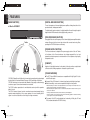
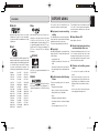
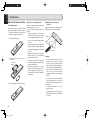
Model ES7001 User Guide
Home Theater System
ES7001U DFU_0_cover.indd III
07.7.31 1:41:49 PM
IMPORTANT SAFETY
INSTRUCTIONS
CAUTION
RISK OF ELECTRIC SHOCK
DO NOT OPEN
CAUTION: TO REDUCE THE RISK OF ELECTRIC SHOCK,
DO NOT REMOVE COVER (OR BACK)
NO USER-SERVICEABLE PARTS INSIDE
REFER SERVICING TO QUALIFIED SERVICE PERSONNEL
The lightning flash with arrowhead symbol within an equilateral triangle is
intended to alert the user to the presence of uninsulated “dangerous voltage”
within the product’s enclosure that may be of sufficient magnitude to constitute
a risk of electric shock to persons.
The exclamation point within an equilateral triangle is intended to alert the
user to the presence of important operating and maintenance (servicing)
instructions in the literature accompanying the product.
WARNING
READ BEFORE OPERATING EQUIPMENT
This product was designed and manufactured to
meet strict quality and safety standards.
There are, however, some installation and operation
precautions which you should be particularly aware
of.
1. Read these instructions.
2.
Keep these instructions.
3.
Heed all warnings.
4.
Follow all instructions.
5.
Do not use this apparatus near water.
6.
Clean only with dry cloth.
7.
Do not block any ventilation openings.
Install in accordance with the manufacture's
instructions.
8.
Do not install near any heat sources such
as radiators, heat registers, stoves, or other
apparatus (including amplifiers) that produce
heat.
TO REDUCE THE RISK OF FIRE OR ELECTRIC SHOCK,
DO NOT EXPOSE THIS APPLIANCE TO RAIN OR MOISTURE.
9.
CAUTION: TO PREVENT ELECTRIC SHOCK, MATCH WIDE BLADE OF PLUG
TO WIDE SLOT, FULLY INSERT.
ATTENTION: POUR EVITER LES CHOCS ELECTRIQUES, INTRODUIRE LA
LAME LA PLUS LARGE DE LA FICHE DANS LA BORNE CORRESPONDANTE DE LA PRISE ET POUSSER JUSQU’AU FOND.
NOTE:
This equipment has been tested and found to
comply with the limits for a Class B digital device,
pursuant to Part 15 of the FCC Rules. These limits
are designed to provide reasonable protection against
harmful interference in a residential installation. This
equipment generates, uses and can radiate radio
frequency energy and, if not installed and used in
accordance with the instructions, may cause harmful
interference to radio communications. However, there
is no guarantee that interference will not occur in a
particular installation. If this equipment does cause
harmful interference to radio or television reception,
which can be determined by turning the equipment
off and on, the user is encouraged to try to correct the
interference by one or more of the following measures:
This Class B digital apparatus complies with Canadian
ICES-003.
- Reorient or relocate the receiving antenna.
- Increase the separation between the equipment and
receiver.
- Connect the equipment into an outlet on a circuit
different from that to which the receiver is connected.
- Consult the dealer or an experienced radio/TV
technician for help.
NOTE:
Use only with the cart, stand, tripod, bracket,
or table specified by the manufacturer, or
sold with the apparatus. When a cart is used,
use caution when moving the cart/apparatus
combination to avoid injury from tip-over.
13.
Unplug this apparatus during lightning storms
or when unused for long periods of time.
14.
Refer all ser vicing to qualified ser vice
personnel. Ser vicing is required when
the apparatus has been damaged in any
way, such as power-supply cord or plug is
damaged, liquid has been spilled or objects
have fallen into the apparatus, the apparatus
has been exposed to rain or moisture, does
not operate normally, or has been dropped.
Additional Safety Information!
• This product should not be placed in a built-in
installation such as a bookcase or rack unless
proper ventilation is provided or the manufacturer’
s instructions have been adhered to.
• Apparatus shall not be exposed to dripping
or splashing and that no objects filled with
liquids, such as vases, shall be placed on the
apparatus.
• When the switch is in the OFF position, the
apparatus isn’t completely switched-off from the
MAINS.
• The equipment shall be installed near the
Socket-Outlet and shall be easily accessible.
DECLARATION OF CONFORMITY
10.
Protect the power cord from being walked on
or pinched particularly at plugs, convenience
receptacles, and the point where they exit
from the apparatus.
11.
Only use attachments/accessories specified
by the manufacturer.
Changes or modifications may cause this unit to fail to
comply with Part 15 of the FCC Rules and may void
the user's authority to operate the equipment.
Cet appareil numérique de la Classe B est conforme à
la norme NMB-003 du Canada.
Do not defeat the safety purpose of the
polarized or grounding-type plug. A polarized
plug has two blades with one wider than the
other. A grounding type plug has two blades
and a third grounding prong. The wide blade
or the third prong are provided for your safety.
If the provided plug does not fit into your
outlet, consult an electrician for replacement
of the obsolete outlet.
12.
This device complies with Part 15 of the FCC rules.
Operation is subject to the following conditions: (1) This
device may not cause harmful interference, and (2) this
device must accept any interference received, including
interference that may cause undesired operation.
U.S. Responsible Party: Marantz America, Inc.
100 Corporate Drive,
Mahwah, NJ, 07430, U.S.A.
TEL: 630-741-0300
Type of Product: Home Theater System
Model:
ES7001
ES_070423U2
ES7001U DFU_0_cover.indd IV
07.7.31 1:41:49 PM
Before using this unit, please read the User Guide carefully to ensure
proper operation of the unit, and retain it together with the supplied
warranty.
ENGLISH
Thank you for purchasing the Marantz Home Theater System.
CONTENTS
FEATURES .................................................................................................. 2
BEFORE USING THIS UNIT........................................................................ 3
NAMES AND FUNCTIONS OF PARTS ....................................................... 5
7 Accessories Check
FRONT PANEL .................................................................................................... 5
Before use, check the below accessories were included in the package.
• Remote controller
• AAA-size batteries x 2
REAR PANEL ...................................................................................................... 6
REMOTE CONTROLLER: RC002ES .................................................................. 7
CONNECTIONS ......................................................................................... 12
CONNECTING DIGITAL EQUIPMENT WITH THE OPTICAL CONNECTOR.... 12
CONNECTING ANALOG EQUIPMENT ............................................................ 13
CONNECTING DIGITAL EQUIPMENT EQUIPPED WITH THE HDMI
CONNECTOR .................................................................................................... 13
• User Guide (This manual)
CONNECTING A SUBWOOFER ....................................................................... 14
REMOTE CONTROL CONNECTIONS ............................................................. 14
INSTALLATION .......................................................................................... 15
BASIC OPERATIONS ................................................................................ 16
TURNING ON THE UNIT................................................................................... 16
PLAYING THE INPUT SOURCE ....................................................................... 16
SETTINGS ................................................................................................. 17
• Warranty Card
(USA x 1, Canada x 1)
SETTING INSTALLATION HEIGHT OF SPEAKERS ........................................ 17
SETTING THE NUMBER OF AUDIENCE ......................................................... 17
SETTING THE VIEWING/LISTENING DISTANCE ........................................... 18
SETTING THE SUBWOOFER OUTPUT ........................................................... 18
SETTING THE BINAURAL MODE .................................................................... 19
SETTING THE DOLBY PRO LOGIC II MODE .................................................. 19
SETTING MULTI-CHANNEL TV SOUND MODE .............................................. 20
SETTING THE NIGHT MODE ........................................................................... 20
SETTING THE DIMMER.................................................................................... 20
RESETTING ITEMS TO FACTORY PRESET SETTINGS ................................ 21
TROUBLESHOOTING ............................................................................... 21
SPECIFICATIONS ..................................................................................... 22
OTHERS .................................................................................................... 22
1
ES7001_U_01_Eng.indd 1
07.7.31 1:42:31 PM
ENGLISH
FEATURES
[MAIN FUNCTION]
[DIGITAL AMPLIFIER SECTION]
¶ What is OPSODIS?
The unit incorporates a 6-channel digital power amplifier, allowing direct drive of the
speakers’ tweeter, midrange and woofer.
The digital audio signals are input to the digital amplifier of the unit through the optical
digital and the HDMI connectors without digital-analog conversion.
[PWM PROCESSOR SECTION]
Using digital filters for cutoff frequency of the 6 channel digital power amplifier enables
extreme filter precision that cannot be achieved with conventional analog filters,
providing the OPSODIS effects more efficiently.
Treble
[POWER SUPPLY SECTION]
The R-core transformer is adopted for the power supply section of this unit. Thanks
to the features of the R-core transformer—less leakage magnetic flux, less heat
generation and quick response to overload variation—the unit produces a high quality
and powerful sound.
[CABINET]
Bass
Bass
Adoption of high-rigidity aluminum for the cabinet of the unit provides a sophisticated
stiff construction, allowing reproduction of beautiful crystalline sound.
[OTHER FEATURES]
OPSODIS (Optimal Source Distribution) is a new virtual surround technology developed
by the Institute of Sound and Vibration Research (ISVR) and Kajima Corporation.
OPSODIS technology has been united with Marantz’s high-quality sound technology
to realize a superior surround environment than ever before.
The ES7001 realizes reproduction of omni-directional sound only with the speakers
built in this unit.
The ES7001 releases listeners from the conventional surround environment that has
required complex installation of five or more speakers. As a result, installing the AV
system in a room has little effect on their lifestyle or living environment.
¶ The OPT IN and HDMI IN connectors are compatible with Dolby Digital 5.1ch, dts
and AAC audio inputs.
¶ Supports Dolby PL II feature for 2-channel signal input and for digital signal input.
¶ Binaural recording* sources can be reproduced through the front speaker.
* Binaural recording is a method of recording audio which uses two microphones mounted in the ears of
a dummy head in the shape of the human head and ears.
Binaural recording can reproduce location of sound behind, ahead, above and below. It makes you feel
a real sense of distance.
Normally, a dramatic binaural effect can be achieved only with headphones.
However, a similar or more stereophonic effect can be achieved by playback of a binaural recording
source using this unit than that with headphones.
¶ The newest 32 bit DSP circuits adopted (one for decoding of Dolby, dts, ACC and
PCM, and two dedicated for OPSODIS circuits)
2
ES7001_U_01_Eng.indd 2
07.7.31 1:42:32 PM
¶ DOLBY
¶ dts
This section must be read before any
connection is made to the mains supply.
7 Equipment mains working
Manufactured under license from Dolby
Laboratories. “Dolby”, “Pro Logic”, the doubleD symbol and “AAC” are trademarks of Dolby
Laboratories.
¶ AAC
AAC is a format of the MPEG2 standard. This
features excellent high-compression encoding
and high-quality sound, enabling reproduction
of 2-channel stereo sound and 5.1-channel
surround, and bilingual broadcast. The
following is the patent numbers of this format.
5848391
5 400 433
5 752 225
5,274,740
4,914,701
5,579,430
97/02875
5,227,788
5,592,584
08/211,547
08/894,844
5,299,240
5,264,846
5,581,654
08/937,950
08/576,495
5,291,557
5,222,189
5,394,473
5,633,981
5,235,671
08/678,666
97/02874
5,285,498
5,781,888
5,703,999
5,299,238
5,197,087
5,268,685
5,548,574
05-183,988
08/392,756
ENGLISH
BEFORE USING
FEATURES
5,451,954
5,357,594
5,583,962
5 297 236
07/640,550
98/03037
98/03036
5,481,614
08/039,478
08/557,046
5,299,239
5,490,170
5,375,189
5,717,821
08/506,729
Manufactured under license under U.S.
Patent No’s: 5,451,942; 5,956,674; 5,974,380;
5,978,762; 6,487,535 & other U.S. and
worldwide patents issued & pending. DTS is
a registered trademark and the DTS logos,
Symbol and DTS Virtual are trademarks of
DTS, Inc. © 1996-2007 DTS, Inc. All Rights
Reserved.
¶ OPSODIS
setting
Your Marantz product has been prepared to
comply with the household power and safety
requirements that exist in your area.
This unit can be powered by 120V AC only.
7 Copyright
Recording and playback of any material may
require consent. For further information refer
to the following:
– Copyright Act 1956
– Dramatic and Musical Performers Act
1958
– Performers Protection Acts 1963 and 1972
OPSODIS is a registered trademark of the
OPSODIS LTD.
¶ HDMI
HDMI, the
and High-Definition
Multimedia Interface are trademarks or
registered trademarks of HDMI Licensing
LLC.
– Any subsequent statutory enactments and
orders
7 Do Not Locate in the Following
Places
To ensure long-lasting use, do not locate the
unit where:
• Exposed to direct sunlight.
• Near to sources of heat such as heaters.
The ventilation holes are located at the rear
of the unit. To ensure proper heat radiation,
ensure the below clearance from walls and
other equipment.
7 Keep Objects Off
Keep objects off the unit.
7 Do not touch hot spots during
and immediately after use
During and immediately after use, the unit
is hot in areas other than the controls and
rear panel connection jacks. Do not touch hot
spots and especially the rear panel. Contact
with hot areas can cause burns.
7 Cautions on handling power
cord
• Do not touch the power cord with wet
hands.
• When disconnecting the power cord,
always make sure that you take hold of the
plug. Yanking out or bending the cord can
damage it and/or cause electric shocks or
a fire.
• Get into the habit of disconnecting the
power plug before leaving home.
• Highly humid or poorly ventilated.
• Dusty.
• Subjected to mechanical vibrations.
• On wobbly, inclined or otherwise unstable
surfaces
• On a high place such as on a TV set
3
ES7001_U_01_Eng.indd 3
07.7.31 1:42:32 PM
ENGLISH
BEFORE USING
7 For use of Remote controller
¶ Loading batteries
Before using the remote controller for the first
time, load the batteries in the remote controller.
The batteries provided are used to verify the
operations of the remote controller only.
q Remove the battery cover.
¶ Cautions on handling batteries
Misuse of the batteries can result in electrolyte
leakage, rupturing, corrosion, etc.
Bear in mind the following points when using
batteries.
• Remove the batteries from the remote
controller if the unit is not going to be used
for a prolonged period (a month or more).
¶ Operatable range of Remote
controller
Operate the unit with the remote controller
within the range of the illustration below.
Approx. 5m
• Do not use an old battery together with a
new one.
• Insert the batteries while ensuring that their
ª and · poles are properly aligned with
the corresponding markings on the remote
controller.
w Inser t the batteries with correct +/–
orientation.
Two AAA-size
batteries
• Batteries with the same shape may have
different voltages. Do not use different
types of batteries together.
• If electrolyte has leaked, thoroughly wipe
the inside of the battery compartment, and
then insert new batteries.
• When batteries which are no longer
required are to be discarded, follow the
directions (regulations) laid down by the
local authorities in the area concerned for
their disposal.
e Close the battery cover until it clicks shut.
Remote controller
Cautions:
• Do not allow direct sunlight, an inverter
fluorescent light or other strong source
of light to shine onto the player’s infrared
receptor window. Otherwise, the operation
of the remote controller may be disabled.
• Bear in mind that operating the remote
controller may cause other devices
operated by infrared rays to be operated by
mistake.
• The remote controller cannot be operated
if the space between the controller and
the player’s infrared receptor window is
obstructed.
• Do not place any objects on top of the
remote controller.
Doing so may cause one or more buttons to
be held down which will cause the batteries
to run down.
4
ES7001_U_01_Eng.indd 4
07.7.31 1:42:33 PM
NAMES AND FUNCTIONS OF PARTS
ENGLISH
o Dolby PL II indicator
The indicator lights in green when 2channel signal is input and the Dolby Pro
Logic II mode is set to Pro Logic II MOVIE
or Pro Logic II MUSIC.
When Dolby Pro Logic II mode is set to
OFF by pressing the Dolby PL II button
on the remote controller, this indicator
goes out.
FRONT PANEL
!0 Dolby D indicator
When a Dolby digital signal is input, this
indicator lights in blue.
!1 dts/AAC/PCM indicator
qw
!2
q ON/STANDBY button
Press this button to turn on the power.
When it is pressed again, the unit goes
into standby mode and the STANDBY
indicator i lights.
w Display window
Normally, the volume level indication (0060) is displayed.
e VOLUME + button
Press this button to increase the volume.
Keeping this button pressed increases the
volume successively.
r VOLUME – button
Press this button to decrease the volume.
Keeping this button pressed decreases
the volume successively.
!1 !0 o i
u y t
t SUB WOOFER indicator
The indicator lights in green when
subwoofer output is activated by pressing
the SUBWOOFER button on the remote
controller.
The indicator goes out when subwoofer
output is set to off by pressing the
SUBWOOFER button on the remote
controller.
The subwoofer output is set to on and the
indicator is lit as the factory-setting mode.
Note:
Before installing this unit, connect a
commercially available or optional Marantz
subwoofer with a built-in amplifier.
y NIGHT MODE indicator
The indicator lights in green when the
night mode function is activated.
The indicator goes out when the night mode
function is canceled by pressing the NIGHT
MODE button on the remote controller.
r
e
Note:
The night mode function can be activated
only when the Dolby D (Digital) indicator
is lit blue.
u MODE indicator
The indicator lights in blue when the
binaural mode is activated. The indicator
goes out when the binaural mode is
canceled by pressing the MODE button on
the remote controller.
Note:
The binaural mode can be set when an
audio source recorded in binaural mode
is played.
i STANDBY indicator
The indicator lights in red when the unit is
in standby mode.
The indicator lights in the following colors
according to the format of digital signal
input from the connected equipment:
dts signal:
red
AAC signal: yellow
PCM signal: green
The indicator goes out when the A1 or A2
button on the remote controller is pressed
to select an analog input signal.
!2 INPUT SELECTOR button
Press this button to select the input source
to be played.
Each press of the button changes the
indication in the display window as shown
below.
The factory-preset setting is “d1.”
A2 (AUX)
d1(DVD)
A1 (VCR)
d2 (TV)
H2(HDMI 2)
H1(HDMI 1)
d3 (GAME)
5
ES7001_U_01_Eng.indd 5
07.7.31 1:42:33 PM
ENGLISH
NAMES AND FUNCTIONS OF PARTS
w ANALOG IN 1 (VCR)/2 (AUX) jacks
REAR PANEL
These jacks are used to connect to the
analog output jacks on a VCR and external
player.
• Connect a VCR to the ANALOG IN 1
jacks. To select the input, press the A1
button on the remote controller.
• Connect an external player to the
ANALOG IN 2 jacks. To select the input,
press the A2 button on the remote
controller.
MODEL NO.ES7001
e SUB W. PREOUT jack
i
q
u
w
This jack is used to connect to the input
jack of an external subwoofer with a builtin amplifier.
r SUB W. CONTROL OUT jack
e
r
Left side of the unit
Right side of the unit
ty
q OPT IN 1 (DVD)/2 (TV)/3 (GAME)
connectors
These connectors are used to connect to
the optical digital output connectors on a
DVD player, TV, video game console, etc.
• Connect a DVD player to the OPT IN 1
connector.
• Connect a TV to the OPT IN 2 connector.
• Connect a video game console to the
OPT IN 3 connector.
Note:
When “d1”, “d2” or “d3” is selected with
the INPUT SELECTOR button on the
unit and no signal is input from the
connected equipment for five minutes,
the unit automatically goes into standby
mode.
This jack is used to connect to the
CONTROL IN jack of the optional Marantz
SW7001 subwoofer with built-in amplifier.
The connected subwoofer is turned on
or goes into standby mode in conjunction
with the operations of the unit.
Note:
To use the control function, turn on the
power of the subwoofer.
t REMOTE OUT jack
This jack is used to connect other Marantz
equipment such as a DVD player equipped
with remote control jack.
Note:
When the Marantz DVD player or the
IS201 iPod universal dock is located in a
place where the infrared beam cannot be
easily received, make a remote control
connection. If you operate the remote
controller pointed toward this unit, a
received command signal is transmitted
to the connected equipment.
y AC power cord
Connect the cord to the wall outlet.
u HDMI IN 1/2 connectors
These connectors are used to connect to
the HDMI output of a hard disk recorder,
TV tuner, video game console, etc.
The HDMI IN/OUT connectors on the unit
are compatible with Version 1.1.
i HDMI OUT connector
This connector is used to connect to the
HDMI input of a TV, video projector, etc.
The HDMI IN/OUT connectors on the unit
are compatible with Version 1.1.
Note:
The audio input to the HDMI jacks can
be played back by this unit.
In such case, audio signals are not
output to the TV or projector.
6
ES7001_U_01_Eng.indd 6
07.7.31 1:42:33 PM
ENGLISH
NAMES AND FUNCTIONS OF PARTS
REMOTE CONTROLLER:
RC002ES
7 Buttons used for this unit
z
x
⁄3
⁄2
⁄1
⁄0
c
v
b
n
m
.
,
z POWER button
Press this button to turn on the unit or to
set it to standby mode.
x Input select buttons
These buttons are used to select the input
source to be played.
Press the input source button you want
to play.
c Dolby PL II button
Press this button to switch the Dolby
Pro Logic II sound field environment.
Each press switches among Pro Logic II
MOVIE, Pro Logic II MUSIC and OFF.
Note:
This button functions when the analog
input signal or 2-ch PCM input signal is
selected.
v NIGHT MODE button
Press this button when you want to lower
the volume of the source for cases such as
movie viewing at night.
As the enhanced parts of the reproduced
sound are suppressed in this mode, you
can enjoy the sound without elevating the
entire volume.
b MODE button
Press this button to listen to the binaural
recording source.
n BILINGUAL button
Press this button to switch the bilingual
sound output from the TV when the unit
receives a high-definition TV broadcast
(AAC audio signal).
m MAIN VOLUME + button
Press this button to increase the volume
of the unit.
, MAIN VOLUME – button
Press this button to decrease the volume
of the unit.
. MUTE button
Press this button to mute the sound
temporarily. Press it again to restore the
sound.
⁄0 DIMMER button
Press this button to dim the display
window.
⁄1 SUBWOOFER button
This button is used to activate a
commercially available or the Marantz
SW7001 subwoofer with a built-in amplifier
connected to the unit.
⁄2 ELEVATION button
Press this button to switch the height of
the unit installation position. “L” (lower than
the TV position) or “H” (higher than the TV
position) can be selected.
⁄3 SEAT button
[For number of audience]
Press this button once to switch the number
of the audience between “1P” (one person)
and “2P” (two or more persons).
[For the viewing/listening distance]
Hold down this button for over 2 seconds to
switch the distance between the audience
and the unit from among “2 m or shorter,”
“Approx. 2 m” and “2 m or longer.”
Notes:
• When the audience is 2.5 m (98 1⁄2
inches) or farther away from the unit
and the viewing/listening distance is
set to “2 m or longer,” the stereophonic
effect of the unit may be reduced.
• When the audience is close 1.5 m
(59 1/8 inches) or less to the unit and
the viewing distance is set to “2 m or
shorter,” the stereophonic effect of the
unit may be reduced.
Note:
This function is activated at the factory.
When no subwoofer is connected to
the unit, press this button to turn off the
indicator.
7
ES7001_U_01_Eng.indd 7
07.7.31 1:42:33 PM
ENGLISH
NAMES AND FUNCTIONS OF PARTS
7 Buttons used for a TV
⁄4 TV POWER button
Notes:
⁄4
• Before using the remote controller for a TV,
set the preset code for the TV.
Press this button to turn on the TV or to set
it to standby mode.
⁄5 TV MUTE button
• For details on the operation of the TV, refer
to the instruction manual supplied with the
TV.
Press this button to mute the TV sound
temporarily. Press it again to restore the
sound.
⁄6 TV VOL + button
Press this button to increase the volume
of the TV.
¤1
¤0
⁄9
⁄5
⁄6
⁄7
⁄7 TV VOL – button
Press this button to decrease the volume
of the TV.
⁄8 Numeric (1-12) buttons
These buttons are used for direct TV
channel selection.
⁄8
⁄9 CH (channel) + button
Press this button to scan forward through
the TV channels.
¤0 CH (channel) - button
Press this button to scan reverse through
the TV channels.
¤1 INPUT SELECT button
7 Preset code setting
The remote control codes of TVs of
manufacturers other than Marantz are preset
in the supplied remote controller. To use
the supplied remote controller for the TV of
another manufacturer, enter the code in the
remote controller.
1. Check the four-digit code number of
your TV manufacturer in the preset code
number lists shown below.
2. While holding down the TV POWER button
⁄4 on the remote controller, press the
Numeric buttons ⁄8 to enter the four-digit
manufacturer’s code number.
Presetting the code number to the remote
controller is complete.
Notes:
• Some of the preset codes in the lists may
not be compatible with your TV.
• If your TV does not operate with the remote
controller after entering the preset code,
try to enter another code number of the
manufacturer.
• Some of the functions of the TV may not be
operable with the remote controller even
after entering the code.
Press this button to switch between the TV
broadcast and a video input.
8
ES7001_U_01_Eng.indd 8
07.7.31 1:42:34 PM
ENGLISH
NAMES AND FUNCTIONS OF PARTS
7 TV preset code number lists
Acer ................................................................ 1141
Admiral ....................................... 1002, 1009, 1089
Aiko................................................................. 1059
Aiwa ...................................................... 1117, 1118
Akai................................................................. 1001
Amtron ............................................................ 1023
Anam .............................................................. 1113
Anam National ............................ 1023, 1069, 1092
AOC .................................. 1003, 1024, 1049, 1127
Audiovox ......................................................... 1023
Bell & Howell ........................................ 1009, 1025
Benq ..................................................... 1104, 1142
Broksonic .......................... 1003, 1097, 1098, 1113
Celebrity ......................................................... 1001
Citizen......................................... 1003, 1013, 1023
1026, 1059, 1063
Colortyme ............................................. 1003, 1043
Contec ............................................................ 1113
Contec/Cony ............................... 1023, 1045, 1047
Craig ................................. 1020, 1022, 1023, 1113
Crown ................................................... 1023, 1067
Curtis Mathes ............................. 1003, 1013, 1025
1026, 1062, 1103, 1110
Daewoo ............................ 1003, 1013, 1024, 1035
1036, 1059, 1084, 1101
Daytron ....................................... 1003, 1013, 1016
Dimensia............................................... 1103, 1110
Dumont ....................................... 1003, 1010, 1153
Electroband .................................................... 1001
Electrohome ..................... 1001, 1003, 1069, 1133
Emerson .................................... 1003, 1013, 1015,
1020, 1021, 1022, 1023
1025, 1038, 1044, 1045
1048, 1055, 1061, 1094
1096, 1099, 1101, 1113
Envision .......................................................... 1003
Fisher................................ 1025, 1051, 1091, 1160
Fujitsu ............................... 1038, 1124, 1125, 1155
Funai........................................... 1023, 1038, 1113
Gateway.......................................................... 1150
GE .................................... 1003, 1018, 1022, 1046
1054, 1069, 1085, 1103
1110, 1113, 1133, 1136, 1153
Goldstar ...................................... 1003, 1013, 1024
1030, 1045, 1080
1100, 1112, 1154
Hallmark ......................................................... 1003
Hisense........................................................... 1116
Hitachi............................... 1003, 1012, 1031, 1032
1037, 1041, 1045, 1047
1065, 1068, 1082, 1088
1094, 1139, 1140, 1145, 1159
Infinity ............................................................. 1067
Janeil .............................................................. 1134
JBL ................................................................. 1067
JC Penney .................................. 1003, 1013, 1018
1019, 1024, 1026
1046, 1047, 1054
1063, 1083, 1085
1100, 1103, 1110
1112, 1133, 1154
Jensen ............................................................ 1003
JVC ............................................. 1028, 1029, 1045
1047, 1050, 1060, 1065
Kawasho ............................................... 1001, 1003
Kenwood ......................................................... 1003
Kloss Novabeam .............. 1023, 1056, 1057, 1134
KTV............................................. 1013, 1023, 1033
1034, 1073, 1099, 1113
LG ......................................................... 1024, 1030
M.Wards ..................................... 1002, 1009, 1038
Magnavox ................................... 1003, 1052, 1053
1056, 1057, 1063
1067, 1081, 1106
Marantz............................. 1003, 1031, 1067, 1122
Mitsubishi.................................... 1003, 1024, 1051
1115, 1122, 1133
Motorola................................................ 1014, 1069
NEC ........................ 1003, 1012, 1024, 1043, 1069
NET-TV ................................................. 1137, 1150
Orion ..................................................... 1020, 1096
Panasonic ............... 1017, 1067, 1069, 1095, 1111
Philips ............................... 1003, 1011, 1045, 1052
1054, 1056, 1057, 1058
1063, 1067, 1069, 1106
Pioneer ....................................... 1003, 1018, 1037
1070, 1071, 1094
1145, 1147, 1149
Plasmsync ...................................................... 1135
Portland ............................ 1003, 1013, 1024, 1059
Price Club ....................................................... 1026
Prism .............................................................. 1018
Proscan ............................ 1004, 1005, 1006, 1007
1008, 1085, 1103, 1110
Proton ................................................... 1003, 1045
Quasar .................... 1010, 1069, 1073, 1111, 1153
Radio Shack .............................. 1003, 1013, 1015,
1023, 1024, 1025, 1045
1100, 1103, 1110, 1113
RCA ............................................ 1003, 1004, 1005
1006, 1007, 1008
1014, 1024, 1049, 1069
1075, 1079, 1085, 1087
1088, 1093, 1094, 1101
1103, 1110, 1113,1153
Realistic ............................ 1013, 1015, 1023, 1025
1045, 1100, 1103, 1110
Runco ................................................... 1010, 1153
Sampo ............................................................ 1150
Samsung .......................... 1003, 1013, 1024, 1026
1040, 1045, 1062, 1078
1083, 1090, 1100, 1105, 1114
1120, 1121, 1146, 1148, 1157
Sansui............................................................. 1119
Sanyo ............................... 1003, 1025, 1051, 1072
1077, 1091, 1156, 1157, 1158
Sharp .......................................... 1003, 1013, 1014
1015, 1045, 1055, 1064
1066, 1076, 1089, 1123
Signature ........................................................ 1009
Sony ........................................... 1001, 1102, 1108
Soundesign............. 1003, 1023, 1038, 1063, 1113
Starlite ............................................................ 1023
Supre-Macy .................................................... 1134
Sylvania ...................................... 1003, 1039, 1042
1052, 1053, 1056, 1057
1063, 1067, 1089, 1151
Symphonic ................................. 1023, 1039, 1044
Tandy .............................................................. 1014
Tatung ............................................................. 1069
Technics.......................................................... 1018
Techwood ............................................. 1003, 1018
Teknika ............................. 1003, 1009, 1013, 1023
1024, 1026, 1038, 1045
1047, 1059, 1063, 1111, 1113
Telecaption ..................................................... 1074
Toshiba ....................................... 1003, 1019, 1025
1026, 1042, 1074, 1098
1107, 1111, 1135, 1136
Totevision ........................................................ 1013
Universal............................................... 1046, 1054
Video Concepts .............................................. 1113
Viewsonic ................................... 1006, 1022, 1109
1128, 1129, 1130, 1131
1138, 1143, 1145, 1150
Wards ......................................... 1003, 1009, 1015
1024, 1038, 1044, 1046
1052, 1054, 1056, 1057
1067, 1086, 1103, 1110
White Westinghouse ............................. 1101, 1001
Yamaha................................................. 1003, 1024
Zenith.......................................... 1003, 1009, 1010
1132, 1144, 1153
9
ES7001_U_01_Eng.indd 9
07.7.31 1:42:34 PM
ENGLISH
NAMES AND FUNCTIONS OF PARTS
7 Before using the remote
7 Buttons used for a Marantz DVD player
controller for Marantz products
1. Press the button specified for the
equipment you want to operate.
• DVD player: “d1” button on the remote
controller
DVD POWER button
Turns on the DVD or sets it to standby mode.
5 button
Moves the cursor up.
∞ button
Moves the cursor down.
• IS201: “A2” button on the remote
controller
2 button
Moves the cursor left.
2. Operate the unit using the buttons described
3 button
Moves the cursor right.
in the respective list.
Notes:
• For details on operation, please refer to
the instruction manual supplied with the
connected Marantz products.
• Some models may not operate with the
remote controller supplied with this unit.
button
Executes the selected item.
TOP MENU button
Displays the top menu of a DVD disc.
MENU button
Displays the setting menu of a DVD player.
REPEAT button
Repeats playback of a chapter or disc.
MODE button
Selects the Super Audio CD sound mode.
7 button
Stops playback.
8 button
Pauses playback.
3 button
Starts playback.
4 button
Returns to the beginning of the current music or chapter.
1 button
Fast backward search
¡ button
Fast forward search
¢ button
Skips to the next music or chapter.
10
ES7001_U_01_Eng.indd 10
07.7.31 1:42:34 PM
7 Buttons used for the Marantz IS201 iPod universal dock
AUX POWER button
Turns on the power of an iPod connected to the IS201 or sets it to
standby mode.
5 button
Functions the same as turning the click wheel of an iPod
counterclockwise.
Note: The iPod volume cannot be adjusted.
∞ button
Functions the same as turning the click wheel of an iPod clockwise.
Note: The iPod volume cannot be adjusted.
button
ENGLISH
NAMES AND FUNCTIONS OF PARTS
Functions the same as the click wheel select button of an iPod.
MENU button
Functions the same as the click wheel menu button of an iPod.
REPEAT button
Switches the iPod repeat mode. (Track repeat → All repeat → Off)
MODE button
Switches the mode of the IS201 (OSD/LCD)
SHUFFLE button
Switches the iPod shuffle mode. (Track → Album → Off)
7 button
Stops iPod playback.
8 button
Pauses iPod playback.
3 button
Starts iPod playback.
4 button
Returns to the beginning of the current content by one press.
Returns to the previous content by two successive presses.
1 button
Fast backward search
¡ button
Fast forward search
¢ button
Skips to the next content by one press.
11
ES7001_U_01_Eng.indd 11
07.7.31 1:42:34 PM
ENGLISH
CONNECTIONS
Notes:
• Do not connect the AC power cords of the
unit and connected equipment to the wall
outlet before making all connections.
• Insert the connecting cable plugs firmly into
the connectors. A loose connection may
result in noise.
• Be sure to connect the L (left) channel
to the white connector, and the R (right)
channel to the red connector.
• Connect the input and output connectors
correctly.
• Please refer to the respective instruction
manual for connected equipment.
CONNECTING DIGITAL
EQUIPMENT WITH THE
OPTICAL CONNECTOR
to OPT digital audio output
• This unit is equipped with three optical
digital inputs.
PLAY
AUDIO EX.
STOP
PAUSE
HDMI
STANDBY
• Use the commercially available optical
connecting cable for connection.
POWER
ON/OFF
AUDIO EX.
HDMI
OPEN/CLOSE
DVD player
7 Connections
to OPT digital audio output
• Connect a DVD player to the OPT IN 1
connector on the unit.
The Marantz DVD player is assigned to the
d1 button on the supplied remote controller,
and the basic operations of the Marantz
DVD player are enabled with the remote
controller.
1
TV
OPT IN
2
3
• Connect a TV to the OPT IN 2 connector on
the unit.
A TV is assigned to the d2 button on the
supplied remote controller, and the basic
operations of the TV are enabled with the
remote controller.
• Connect a video game console to the OPT
IN 3 connector on the unit.
to OPT digital audio output
Right side of the unit
A video game console is assigned to the d3
button on the supplied remote controller.
Video game console
12
ES7001_U_01_Eng.indd 12
07.7.31 1:42:35 PM
CONNECTING DIGITAL EQUIPMENT EQUIPPED WITH THE
HDMI CONNECTOR
CONNECTING ANALOG EQUIPMENT
• This unit is equipped with two analog inputs.
• Use a commercially available RCA audio cable for connection.
ENGLISH
CONNECTIONS
• This unit is equipped with two HDMI digital inputs and one HDMI digital output.
• Use a commercially available HDMI connecting cable for connection.
7 Connections
Note:
• Connect a VCR to the ANALOG IN 1 connector on the unit.
A VCR is assigned to the A1 (VIDEO) button on the supplied remote controller.
• Connect the IS201 iPod universal dock to the ANALOG IN 2 connector on the unit.
The IS201 is assigned to the A2 (AUX) button on the supplied remote controller, and the basic
operations of the IS201 are enabled with the remote controller.
The audio input to the HDMI jacks can be played back by this unit.
In such case, audio signals are not output to the TV or projector.
7 Connections
• Connect a hard disc recorder, etc. equipped with an HDMI connector to the HDMI IN 1
connector on the unit.
The connected equipment is assigned to the H1 button on the supplied remote controller.
• Connect a video game console equipped with an HDMI connector to the HDMI IN 2 connector
on the unit.
VCR
to HDMI input
to analog audio output
L
TV or video
projector
R
HDMI OUT
to HDMI output
1
L
R
ANALOG IN
2
L
Right side of the unit
to analog audio output
R
HDMI
Ver1.1
Hard disc recorder,
TV tuner, etc.
HDMI IN 1
HDMI IN 2
Left side of the unit
Video game console
to HDMI output
R L
IS201 iPod universal dock
13
ES7001_U_01_Eng.indd 13
07.7.31 1:42:35 PM
ENGLISH
CONNECTIONS
CONNECTING A SUBWOOFER
REMOTE CONTROL CONNECTIONS
• For connection with the optional SW7001 subwoofer, use the connecting cable supplied with
the SW7001.
• The REMOTE OUT jack is used for connection with the Marantz DVD player, etc. equipped
with remote control output.
• If the power of the SW7001 is turned on after connection, it will be turned on or goes into
standby mode in conjunction with the operations of the unit. This function is not available with
other manufacturers’ subwoofers.
• When the Marantz DVD player or the IS201 is located in a place where the infrared beam
cannot be easily received, make a remote control connection. When you operate the remote
controller pointing toward this unit, a received command signal is transmitted to the connected
equipment.
7 Connections
• Connect the SUB W. PREOUT jack on the unit to the input jack on the SW7001.
• Connect the SUB W. CONTROL OUT jack on the unit to the control input jack on the
SW7001.
7 Connections
• Connect the Marantz DVD player to the REMOTE OUT jack on the unit using the remote
control cable supplied with the player.
Note:
For this connection, set the remote control switch on the rear panel of the connected
equipment to EXT.
to input jack
to control
input jack
INT
EXT.
OUT IN
to remote
control input
Remote control
switch
PLAY
SUB W. PREOUT
AUDIO EX.
Right side of the unit
PAUSE
REMOTE OUT
ON/OFF
AUDIO EX.
SUB W. CONTROL
OUT
STOP
HDMI
STANDBY
POWER
HDMI
OPEN/CLOSE
Marantz CD/DVD player
Right side of the unit
SW7001 subwoofer
with a built-in amplifier
(optional)
14
ES7001_U_01_Eng.indd 14
07.7.31 1:42:35 PM
7 Installing the unit
[To mount the unit in the optional AV rack]
ENGLISH
INSTALLATION
• Install the unit so that the center of the seat is aligned with the center of the unit.
ES7001
ES7001
ES7001
App
rox.
2m
(78
3/4
AV rack
inch
es)
• When mounting the unit in a rack, align the front surface of the rack with the front of the
unit.
Front surface of
upper rack shelf
Front of the unit
Rear of the unit
[To install the unit in a higher place than the connected TV]
Side of the unit
Front surface of
lower rack shelf
Notes:
• Do not place the unit on the surface of an object generating heat such as a CRT-based TV.
m s)
. 2 he
ox nc
pr /4 i
Ap 8 3
(7
• The unit weighs 12 kg (26 lb 7 oz). Use commercially available wires, etc. to take measures
to prevent the unit from falling due to vibration caused by earthquake or mishandling by
children.
• If the TV picture is blurred, install the unit apart from the TV.
15
ES7001_U_01_Eng.indd 15
07.7.31 1:42:35 PM
ENGLISH
BASIC OPERATIONS
TURNING ON THE UNIT
1. Turn on the power of the audio equipment
connected to this unit. Set the input selector
on the audio equipment to this unit.
2. Connect the AC power cord to the wall
outlet.
3. Press the ON/STANDBY button q on the
unit or POWER button z on the remote
controller to turn on the power of the unit.
• Each time the button is pressed, the
power of the unit is switched between on
and standby mode.
7 Auto-power-off function
• If the power of the connected DVD player,
TV, video game console, etc. is turned off
and the power of the unit remains on, the
unit automatically goes into standby mode.
• If no signal is input to this unit for five
minutes with the input selector set to “DVD,”
“TV” or “GAME,” the unit automatically goes
into standby mode.
PLAYING THE INPUT
SOURCE
The procedure for operating the unit for
playback with a DVD player is described below
as a representative example.
Check that the DVD player and the unit are
correctly connected, referring to “Connections”
in this Guide.
Flashes while the muting function is activated.
!2
q
r
e
7 To play a DVD disc with the
DVD player
z
1. Turn on the power of the DVD player.
2. Press the ON/STANDBY button q on the
x
unit or POWER button z on the remote
controller to turn on the unit.
3. Press the INPUT SELECT button !2 on
the unit repeatedly to select “d1” or the d1
button of the input select buttons x on the
remote controller.
m
.
,
4. Load a disc into the DVD player and start
playback.
5. Adjust the volume with the VOLUME
+/– buttons e/r on the unit or the MAIN
VOLUME +/– buttons m/, on the remote
controller.
7 Muting function
Press the MUTE button . on the remote
controller to mute the sound temporarily.
While the muting function is activated, the
volume level indication flashes in the display
window.
To restore the sound, press the MUTE button
. or the MAIN VOLUME +/- buttons m/,
on the remote controller, or the VOLUME
+/– buttons e/r on the unit.
16
ES7001_U_01_Eng.indd 16
07.7.31 1:42:36 PM
ENGLISH
SETTINGS
The following setting items are available with
this unit.
• Setting Installation Height of Speakers
(page 17)
SETTING INSTALLATION
HEIGHT OF SPEAKERS
• Setting the number of audience (page 17)
• This item is used to set the installation
location (height) of the unit.
• Setting the viewing/listening distance
(page 18)
• Press the ELEVATION button on the remote
controller to change the setting.
• Setting the subwoofer output (page 18)
• Each time the button is pressed, the setting
switches as described below.
• Setting the binaural mode (page 19)
• Setting the Dolby Pro Logic II (page 19)
• Mode setting multi-channel TV sound
mode (page 20)
• Setting the night mode (page 20)
• Setting the dimmer (page 20)
• Resetting Items to factory preset settings
(page 21)
• This item is set at the factory as if the unit is
installed in a lower place than the connected
TV (mounted on the upper shelf of the
optional RM7001 AV).
SETTING THE NUMBER
OF AUDIENCE
¶ When audience is one person
ES7001
• This item is used to set whether you view/
listen to the source input to this unit alone
or with multiple persons in a room.
• Press the SEAT button on the remote
controller to switch to “2 or more persons.”
• This item is set to “2 or more persons” at
the factory.
Mounted in the RM7001 rack
Installed in a higher place than the TV
SEAT button
¶ When audience is two or more
persons
ES7001
ES7001
ELEVATION
button
¶ When the unit is mounted in the
RM7001 rack
¶ When the unit is installed in a
higher place than the connected TV
Note:
When there is a large audience, try both
settings and select the setting which gives
a better stereophonic effect.
17
ES7001_U_01_Eng.indd 17
07.7.31 1:42:36 PM
ENGLISH
SETTINGS
SETTING THE VIEWING/
LISTENING DISTANCE
¶ When the distance is shorter than
2 m (78 3⁄4 inches)
• This item is used to set the distance
between the unit and audience.
• Hold down the SEAT button on the remote
controller for over two seconds to change
the setting.
Each time you hold down the button for over
two seconds while the viewing/listening
distance indication is displayed in the
display window, the setting switches as
described below.
This item is set to “Approx. 2 m” at the
factory.
2 m or
shorter
Approx.
2m
2 m or
longer
¶ When the distance is approximately
2 m (78 3⁄4 inches)
¶ When the distance is longer than
2 m (78 3⁄4 inches)
Notes:
SEAT button
(Hold down over
two seconds.)
• When the audience is 2.5 m (98 1⁄2 inches)
or farther away from the unit with the
viewing/listening distance set to “2 m or
longer,” the stereophonic effect of the
speakers may be reduced.
• When the audience is close 1.5 m (59 1/8
inches) or less to the unit with the viewing/
listening distance set to “2 m or shorter,” the
stereophonic effect of the speakers may be
reduced.
SETTING THE
SUBWOOFER OUTPUT
• Press the SUBWOOFER button on the remote
controller when you use a commercially
available or optional SW7001 subwoofer with
a built-in amplifier so that the SUB WOOFER
indicator lights. The subwoofer output is
activated, enabling output of low-frequency
sound from the connected subwoofer.
The low-frequency sound from this unit is
adjusted so that it does not overlap with that
from the connected subwoofer.
• To turn off the subwoofer output, press
the SUBWOOFER button on the remote
controller once to display the “On” indication
in the display window, then press it again
while the indication is displayed.
The indication in the display window
changes to “OF” and the SUB WOOFER
indicator goes out. The subwoofer output
is set to off and low-frequency sound of the
unit is restored.
• This setting is set to “On” at the factory.
SUBWOOFER
button
Lights
¶ When the subwoofer output is set to on
¶ When the subwoofer output is set to off
Notes
• Be sure to set the subwoofer output to off
when you do not use an external subwoofer.
Optimum low-frequency sound is only
output from the speakers built in the unit
with the subwoofer output set to off.
• You cannot adjust the volume level of the
connected subwoofer with this unit. Adjust
it with the connected subwoofer.
18
ES7001_U_01_Eng.indd 18
07.7.31 1:42:36 PM
ENGLISH
SETTINGS
SETTING THE BINAURAL
MODE
¶ When “PL II MOVIE” is selected
SETTING THE DOLBY
PRO LOGIC II MODE
• To change the setting, press the Dolby PL II
button repeatedly.
• Press the MODE button on the remote
controller to listen to the audio source
recorded in binaural mode.
• This item is used to select the sound field
environment produced by Dolby Pro Logic
II.
• The MODE indicator lights in blue and the
stereophonic effect of the sound source is
reproduced especially realistically.
• When the unit is set to “PL II MOVIE” or “PL
II MUSIC,” the Dolby PL II indicator lights.
Note:
The binaural mode is automatically
canceled when a sound source other than
2-channel PCM sound or analog sound is
input.
• Each time you press the Dolby PL II button
on the remote controller, the sound field
setting changes as follows:
PL II MOVIE
PL II MUSIC
Notes:
• The selected setting of Dolby Pro Logic II
mode is saved in the unit.
Stereophonic effect is obtained from the
soundtrack of a stereo movie encoded by
Dolby Surround.
¶ When “PL II MUSIC” is selected
OFF
Stereophonic effect is obtained from a
conventional stereo source such as a CD
player, iPod, etc.
Dolby PL II
button
MODE
button
Lights
Lights
¶ When “OFF” is selected
The Dolby Pro Logic II mode is turned off.
If the signal source is input from the ANALOG
IN 1 (VCR) or 2 (AUX) jacks, or 2-channel
digital signal is input when the Dolby Pro
Logic II mode is set to “PL II MOVIE” or “PL II
MUSIC,” the setting is automatically switched
to “PL II MOVIE” and the Dolby PL II indicator
lights.
19
ES7001_U_01_Eng.indd 19
07.7.31 1:42:37 PM
ENGLISH
SETTINGS
SETTING MULTI-CHANNEL
TV SOUND MODE
• When the unit receives a high-definition
broadcast (AAC signal), the AAC indicator
lights in yellow.
In this case, you can select the output sound
from the TV by pressing the BILINGUAL
button on the remote controller.
¶ When “Main channel” is selected
SETTING THE NIGHT MODE
¶ When “Sub channel” is selected
This mode is convenient for enjoying a movie,
etc. at night. You can enjoy the playback sound
without elevating the entire volume as only the
enhanced parts of the sound are suppressed
in this mode. Press the NIGHT MODE button
on the remote controller to activate this mode.
The NIGHT MODE indicator lights in green
on the unit.
The night mode is only available when the
Dolby Digital indicator is lit in blue.
¶ When “Main+Sub” is selected
Note:
• Each press of the button changes the
sound as follows:
Main
channel
Sub
channel
Main + Sub
Since the night mode effect is set by the
Dolby digital software, the desired effect
may not be achieved with software that
does not support the Dolby digital signal.
This mode cannot be used when a dts,
AAC or PCM signal is input.
SETTING THE DIMMER
Press the DIMMER button on the remote
controller to dim the display window of the
unit. To cancel the dimmer mode, press the
button again.
DIMMER
button
Note:
BILINGUAL
button
Some broadcasts may not feature multichannel audio (AAC signal).
NIGHT MODE
button
Lights
Lights
20
ES7001_U_01_Eng.indd 20
07.7.31 1:42:37 PM
RESETTING ITEMS TO
FACTORY PRESET SETTINGS
To reset all the items that have been set to the
factory preset settings (initial settings), hold
down the ON/STANDBY button and VOLUME
+ button on the unit simultaneously for over 3
seconds while the power of the unit is on.
After two seconds, the unit goes into standby
mode, turns on again, then the settings are
reset to their factory preset ones.
7 Initial settings of unit
Power ...................................................... ON
Input selector .......................................... DVD
Display window ...........volume level indication
Volume level .............................................. 00
7 Initial settings of setting items
Speaker installation height .......................... L
(installed in a lower place than the connected TV)
Number of audience ....2P (2 or more persons)
Viewing/listening distance ............... – – (2 m)
Subwoofer .. On (subwoofer output activated)
Binaural mode ........................................... off
Dolby PL II ..........................P1 (PL II MOVIE)
Multi-channel broadcast ....b1 (main channel)
Night mode ................................................ off
Dimmer ..............................normal brightness
Muting ....................................................... off
ENGLISH
SETTINGS
TROUBLESHOOTING
7 Before considering it as a failure
In case of trouble with this component, first check the following before calling for service.
What seems to be a serious malfunction is often due to a simple operation mistake.
If the trouble is not fixed after making the following checks, contact the place of purchase, your nearest Marantz dealer, our customer service
center, or our repair service center.
Power does not turn on.
outlet securely?
Noises appear while the CD or
LD that contains dts signal is
played.
\ Plug in the power cord securely.
1. Is the playback equipment not connected
1. Is the power cord inserted into the wall
to the ANALOG IN jacks on the unit?
2. Is the STANDBY indicator lit?
\ Press the POWER button on the
remote controller.
No sound is heard from the
speakers.
1. Is input source selection with the INPUT
SELECTOR buttons on the front panel
correct?
\ Check that the playback equipment
is equipped with digital output, and
connect it to the digital input on this
unit.
2. Does the CD or LD support the dts signal
output?
\ Refer to the instruction manual
supplied with the playback equipment.
\ Check that the input source is selected
correctly.
96 kHz PCM signal cannot be
played.
2. Are you operating the playback equipment
1. This unit is compatible with 32 kHz, 44.1
correctly?
kHz and 48 kHz sampling frequencies.
\ Refer to the instruction manual
supplied with the playback equipment.
\ Downsample the DVD player audio to
48 kHz.
3. Are the connecting cables between the
unit and the playback equipment correctly
connected?
\ Connect the connecting cables
correctly.
4. Is the muting function deactivated?
\ Set the muting function to off.
7 About the Protective Circuit
This unit incorporates a protective circuit that
protects the amplifier circuits and speaker
system against damage.
As soon as the protective circuit works, the unit
goes into standby mode and the STANDBY
indicator flashes at the same time.
¶ For power-on
For 3 or 4 seconds after the power of the unit
is turned on the protective circuit works and
the sound is muted. Once the amplifier circuits
are stabilized, the protective circuit is released
and the sound is restored.
¶ For heat-up of the power amplifier
When the power amplifier of the unit heats up
under the following conditions, the protective
circuit works and the unit goes into the standby
mode.
• The unit is kept used with excessive signal
input, and the temperature of the main
amplifier section exceeds the set operating
temperature.
• Since the ventilation holes at the rear of the
unit are blocked or the unit is installed in a
narrow rack, the internal temperature of the
unit exceeds the set operating temperature.
In this case, wait until the temperature is
sufficiently lowered, then turn on the unit and
operate it at a lower volume.
21
ES7001_U_01_Eng.indd 21
07.7.31 1:42:38 PM
ENGLISH
SPECIFICATIONS
OTHERS
¶ Audio power amplifier
¶ Input
Rated power output (20 Hz-20 kHz / THD = 0.05%)
.........................................26 W/ch 6Ω
Maximum power output (1 kHz/JEITA)
.........................................30 W/ch 6Ω
Frequency characteristics
Analog input: ANALOG IN 1
........................20 Hz-20 kHz (± 3 dB)
Digital input: PCM 44.1 kHz
........................20 Hz-20 kHz (± 3 dB)
S/N ratio: PCM 44.1 kHz
................................................ 100 dB
OPT IN (optical digital) ......................3 inputs
HDMI IN (Version 1.1) ......................2 inputs
ANALOG IN ......................... 2 inputs (stereo)
¶ Decoding
Compatible playback signal formats
PCM audio (fs = 32 kHz, 44.1 kHz, 48 kHz)
DOLBY DIGITAL
dts
AAC
Binaural
¶ Power supply
Power requirements............. AC 120 V, 60 Hz
Power consumption ............................... 40 W
............ 125 W (6Ω, 30 W x 2 outputs)
Power consumption in standby mode ... 0.8 W
¶ Output
HDMI OUT (Version 1.1) .................. 1 output
SUB W. PREOUT ............................. 1 output
REMOTE OUT .................................. 1 output
¶ Speakers
Tweeter ............ 1.9 cm (3/4 inches) dome x 2
Midrange............8 cm (3 1⁄4 inches) cone x 2
Woofer .............12 cm (4 3⁄4 inches) cone x 2
¶ Dimensions (unit)
Width .................1,080 mm (42 9/16 inches)
Height ......................153 mm (6 1/16 inches)
Depth ....................144 mm (5 11/16 inches)
Mass (unit) ..........................12 kg (26 lb 7 oz)
¶ Supplied accessories
Remote controller ........................................ 1
AAA batteries .............................................. 2
User Guide (this manual)............................. 1
The section descr ibes the care and
maintenance tasks that must be performed
to optimize the operation of your Marantz
component.
7 Cleaning of equipment external
surfaces
The exterior finish of your unit will last
indefinitely with proper care and cleaning,
Never use scouring pads, steel wool, scourging
powders or harsh chemical agents (e.g., lye
solution), alcohol, thinner, benzine, insecticide
or other volatile substances as these wil mar
the finish of the equipment. Likewise, never
use cloths containing chemical substances.
If the equipment get dirty, wipe the external
surfaces with a soft, lint-free cloth.
If the equipment becomes heavily soiled:
7 Repairs
Only the most competent and qualified
service technicians should be allowed to
service the factory-trained warranty station
personnel have the knowledge and special
facilities needed for repair and calibration of
this precision equipment. After the warranty
period has expired, repairs will be performed
for a charge if the equipment can be returned
to normal operation.
In the event of difficulty, refer to your dealer or
write directly to the nearest location to you that
is listed on the Marantz Authorized Service
Station list. If writing, please include the model
and serial number of the equipment together
with a full description of what you think is
abnormal about the equipment’s behaviour.
• dilute some washing up liquid in water, in
a ratio of one part detergent to six parts
water.
• dip a soft, lint free in the solution and wring
the it is damp.
• wipe the equipment with the damp cloth.
Note:
• dry the equipment by wiping it with a dry
cloth.
144
The speaker nets cannot be removed.
2
153
1080
Specifications subject to change without prior notice.
22
ES7001_U_01_Eng.indd 22
07.7.31 1:42:38 PM
www.marantz.com
You can find your nearest authorized distributor or dealer on our website.
is a registered trademark.
Printed in Japan
ES7001U DFU_0_cover.indd II
07/2007 00M20AJ851250 mzh-g
07.7.31 1:41:49 PM