1
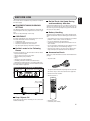
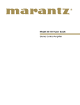
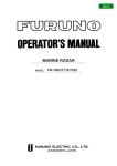
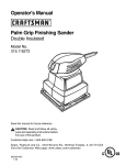
Model PM7001 User Guide
Integrated Amplifier
CAUTION
RISK OF ELECTRIC SHOCK
DO NOT OPEN
CAUTION: TO REDUCE THE RISK OF ELECTRIC SHOCK,
DO NOT REMOVE COVER (OR BACK)
NO USER-SERVICEABLE PARTS INSIDE
REFER SERVICING TO QUALIFIED SERVICE PERSONNEL
The lightning flash with arrowhead symbol within an
equilateral triangle is intended to alert the user to
the presence of uninsulated “dangerous voltage”
within the product’s enclosure that may be of
sufficient magnitude to constitute a risk of electric
shockto persons.
The exclamation point within an equilateral triangle
is intended to alert the user to the presence of
important operating and maintenance (servicing)
instructions in the literature accompanying the
product.
WARNING
TO REDUCE THE RISK OF FIRE OR ELECTRIC SHOCK,
DO NOT EXPOSE THIS PRODUCT TO RAIN OR MOISTURE.
CAUTION: TO PREVENT ELECTRIC SHOCK, MATCH WIDE
BLADE OF PLUG TO WIDE SLOT, FULLY INSERT.
ATTENTION: POUR ÉVITER LES CHOC ÉLECTRIQUES,
INTRODUIRE LA LAME LA PLUS LARGE DE LA FICHE DANS
LA BORNE CORRESPON-DANTE DE LA PRISE ET POUSSER
JUSQU’AU FOND.
IMPORTANT SAFETY
INSTRUCTIONS
READ BEFORE OPERATING EQUIPMENT
This product was designed and manufactured to meet strict quality and safety standards. There are,
however, some installation and operation precautions which you should be particularly aware of.
1. Read these instructions.
2. Keep these instructions.
3. Heed all warnings.
4. Follow all instructions.
5. Do not use this apparatus near water.
6. Clean only with dry cloth.
7. Do not block any ventilation openings. Install in accordance with the manufacture's instructions.
8. Do not install near any heat sources such as radiators, heat registers, stoves, or other apparatus
(including amplifiers) that produce heat.
9. Do not defeat the safety purpose of the polarized or grounding-type plug. A polarized plug has two blades
with one wider than the other. A grounding type plug has two blades and a third grounding prong. The
wide blade or the third prong are provided for your safety. If the provided plug does not fit into your outlet,
consult an electrician for replacement of the obsolete outlet.
10. Protect the power cord from being walked on or pinched particularly at plugs, convenience receptacles,
and the point where they exit from the apparatus.
11. Only use attachments/accessories specified by the manufacturer.
12. Use only with the cart, stand, tripod, bracket, or table specified by the manufacturer, or sold with the
apparatus. When a cart is used, use caution when moving the cart/apparatus combination to avoid injury
from tip-over.
13. Unplug this apparatus during lightning storms or when unused for long periods of time.
14. Refer all servicing to qualified service personnel. Servicing is required when the apparatus has been
damaged in any way, such as power-supply cord or plug is damaged, liquid has been spilled or objects
have fallen into the apparatus, the apparatus has been exposed to rain or moisture, does not operate
normally, or has been dropped.
Additional Safety Information!
• This product should not be placed in a built-in installation such as a bookcase or rack unless proper
ventilation is provided or the manufacturer’s instructions have been adhered to.
• Apparatus shall not be exposed to dripping or splashing and that no objects filled with liquids, such as
vases, shall be placed on the apparatus.
• When the switch is in the OFF position, the apparatus isn’t completely switched-off from the MAINS.
ENGLISH
CONTENTS
BEFORE USE ........................................................................................................................................ 1
FEATURES ............................................................................................................................................ 2
BEFORE MAKING CONNECTIONS ..................................................................................................... 3
WIRING SPEAKER CABLE ................................................................................................................................ 3
BI-WIRING CONNECTION ................................................................................................................................. 3
CONNECTIONS .................................................................................................................................... 4
NAMES AND FUNCTIONS OF PARTS ................................................................................................. 6
FRONT PANEL ................................................................................................................................................... 6
REAR PANEL ..................................................................................................................................................... 7
RC4001PM REMOTE CONTROLLER ................................................................................................................ 8
BASIC OPERATION ............................................................................................................................ 11
PLAYBACK ........................................................................................................................................................ 11
RECORDING .................................................................................................................................................... 11
HOW TO USE AND SET FEATURES .................................................................................................. 12
MAIN IN JACKS ................................................................................................................................................ 12
REMOTE CONTROL JACKS ............................................................................................................................ 13
TROUBLESHOOTING ......................................................................................................................... 14
OTHERS .............................................................................................................................................. 15
SPECIFICATIONS & DIMENSIONAL DRAWINGS .............................................................................. 15
ENGLISH
BEFORE USE
This section must be read before any connection is made to
the mains supply.
7 Do Not Touch Hot Spots During
and Immediately After Use
7 EQUIPMENT MAINS WORKING
SETTING
During and immediately after use, the PM7001 is hot in areas
other than the controls and rear panel connection jacks. Do
not touch hot spots and especially the top panel. Contact with
hot areas can cause burns.
Your Marantz product has been prepared to comply with the
household power and safety requirements that exist in your
area.
PM7001 can be powered by 120V AC only.
7 COPYRIGHT
Recording and playback of any material may require consent.
For further information refer to the following:
— Copyright Act 1956
— Dramatic and Musical Performers Act 1958
— Performers Protection Acts 1963 and 1972
— Any subsequent statutory enactments and orders
7 Do Not Locate in the Following
Places
To ensure long-lasting use, do not locate the PM7001 where:
• Exposed to direct sunlight.
• Near to sources of heat such as heaters.
• Highly humid or poorly ventilated.
• Dusty.
• Subjected to mechanical vibrations.
• On wobbly, inclined or otherwise unstable surfaces
• Radiated heat is blocked such as in cramped audio racks.
To ensure proper heat radiation, ensure the below clearance
from walls and other equipment.
Above 7-7/8 ins. Right 7-7/8 ins.
(0.2 m) or more (0.2 m) or more
Left 7-7/8 ins.
(0.2 m) or more
INTEGRATED AMPLIFIER PM7001
INPUT SELECTOR
VOLUME
PHONO
STANDBY
POWER ON/OFF
CD
REC
SELECTOR
OFF
PHONES
TUNER
AUX/DVD
TUNER
AUX/DVD
1
BASS
RECORDER
TREBLE
BALANCE
MIN
CD
A
MAX
SPEAKERS
SOURCE DIRECT
B
PHONO
ON
OFF
RECORDER1
RECORDER2
+
-
+
Improper use of dry cell batteries can result in electrolyte leaks,
rupture and corrosion. Read the following precautions before
use.
• If not planning to use the remote controller for an extended
period of 1 month or more, remove the batteries.
• Do not mix old batteries with new batteries.
• Load batteries in the proper direction indicated on the remote controller.
• Do not mix batteries of differing type. Even batteries of the
same shape and size can have differing voltages.
• If batteries leak, wipe the case clean of any adhering electrolyte and replace the old batteries with new batteries.
7 Accessories Check
Before use, check the below accessories were included in the
package.
• AC power cable
The power cable included in the package can be used with
the PM7001 only. It cannot be used with other equipment.
2
ON
OFF
COPY
RECORDER2
RECORDER1
-
7 Battery Handling
L
R
• RC4001PM remote controller
• AA-size batteries x 2
Rear 7-7/8 ins.
(0.2 m) or more
7 Keep Objects Off
Keep objects off the PM7001. Blocking the vent can result in
accident and damage.
• Registration Card
• User Guide (This manual)
1
ENGLISH
FEATURES
INTEGRATED AMPLIFIER PM7001
INPUT SELECTOR
VOLUME
PHONO
CD
TUNER
AUX/DVD
1
RECORDER
2
MUTE
STANDBY
REC SELECTOR
OFF
POWER ON/OFF
TUNER
PHONES
AUX/DVD
BASS
TREBLE
BALANCE
MIN
1
CD
MAX
SPEAKERS
2
SOURCE DIRECT
PHONO
ON
OFF
RECORDER
2 1
ON
OFF
COPY
RECORDER2
1
2
-
+
The PM7001 is an integrated amplifier developed on the design
concepts of Marantz’s PM-11S1 high-end model amplifier.
• CD Direct Buffer Amplifier
The PM7001 incorporates a specialized input buffer amplifier
nearby the CD input jack. This buffer amplifier faithfully transmits
the CD input jack signal by preventing interference from
between the left and right channels, and from the effects of
other circuits. A discrete configuration high-speed buffer
amplifier which is built on the HDAM ®SA technology is
incorporated into the buffer amplifier circuit.
• CD Direct Selector
The output of CD direct buffer amplifier has a specialized relay
switch, which directly transmits the input signal by the shortest
path to the pre-amplifier.
• Improved Momentary-Current Supply
Capability
It is known that sound quality differs between amplifiers that
use the same spec, and Marantz believes that this is caused
by differences in speaker drive capability. The PM7001 mainamplifier has the capability to momentarily pass 25 amperes
or more of current, providing high-powered drive to the
speakers.
2
-
+
L
R
• Short Power Line Layout
In order to improve the momentary-current supply capability,
a new layout which places priority on making the large current
line connections as short as possible was adopted.
In this layout the power supply circuit, main-amplifier output
stage, and heatsink are unified, and the large current line is
arranged to be as short as possible while still achieving
symmetry on the left and right sides.
• Current Feedback Amplifier
Both pre-amplifier and main-amplifier incorporate a high-speed
current feedback amplifier circuit, which faithfully amplify
signals from the CD player. Moreover, the high-speed current
feedback amplifier reproduces a natural sound field space.
WIRING SPEAKER CABLE
• Be careful not to short circuit in wiring speaker cables.
• Peel off the corting of speaker cable as shown below.
Approx.
7/16 ins. (10 mm)
Cut the corting of
cable.
Peel off the
edge of cable.
Twist
conductors.
Insert conductor
of cable.
BI-WIRING CONNECTION
A bi-wiring connection separately connects the low and mid/
high jacks of the speaker to the amplifier using separate
speaker cables. Because separate cables are used for low
and mid/high sounds, the kick back current in the low speaker
causes little interference with the mid/high speaker. The
PM7001 and speakers of Connection Example 1 (pg. 5) use a
bi-wiring connection, therefore also refer to that page for help.
• Wiring with speaker cable.
Turn counter-clockwise
to loosen.
Here following is explained BI-WIRING connection that improve sound quality. The speakers in this explanation have
low and mid/high input jacks that support a BI-WIRING connection. To determine whether or not your speakers support a
BI-WIRING connection, check in the instruction manual that
came with your speakers or contact the manufacturer.
Turn clockwise
to tighten.
CD
player,
etc.
PM7001
Bi-wiring Speaker system
connection
Mid/high
speaker
Band
pass filter
Low
speaker
Your speaker system must satisfy the below conditions. If it
does not, the PM7001’s protective circuit will active, whereby
preventing proper playback. In some cases, the amplifier and
speakers may be damaged.
• If using 1 set of speakers, total speaker impedance must be
4Ω or more.
• If using 2 sets of speakers, total speaker impedance must
be 8Ω or more.
3
ENGLISH
BEFORE MAKING CONNECTIONS
ENGLISH
CONNECTIONS
Connection Example : Basic Connection for Stereo Playback
Refer also to the instruction manuals of components to connect equipment correctly.
Record Player
To LINE OUT jacks
CD player
PRE OUT
PHONO
GND
L
MAIN IN
L
L
R
R
To LINE OUT jacks
R
CD
Tuner
TUNER
AUX
/ DVD
RECORDER 1
IN
OUT
RECORDER 2
IN
OUT
L
L
R
R
SEPARATE
To LINE OUT jacks
DVD Player
To LINE OUT jacks
CD-R, etc.
To LINE IN jacks
To LINE OUT jacks
MD or Tape deck, etc.
To LINE IN jacks
4
ENGLISH
CONNECTIONS
Main-amplifier
Speaker
Speaker
If you have another mainamplifier, you can use the
PM7001 as the pre-amplifier
by connecting as shown in
the diagram below.
POWER ON/OFF
To input jacks
To power outlet
PHONO
PRE OUT
SPEAKERS
MAIN IN
R
GND
L
L
L
R
R
SYSTEM 1
L
MODEL NO. PM7001
R
AC IN
SYSTEM 2
SERIAL NO.
CD
TUNER
AUX
/ DVD
RECORDER 1
IN
OUT
REMOTE
CONTROL
RECORDER 2
IN
OUT
IN
L
L
SYSTEM 1 OR SYSTEM 2 4
4-16
16 OHMS
SYSTEM 1 AND SYSTEM 2 8
8-16
16 OHMS
OUT
SEPARATE
R
R
ON
OFF
Set to “OFF”
Remove
shorting
bar.
MF / HF
MF / HF
LF
LF
L CH
speaker
Remove
shorting
bar.
Remove
shorting
bar.
R CH
speaker
Remove
shorting
bar.
• Use a bi-wiring connection (pg. 3) for speakers.
• Set the SPEAKERS button 1 and button 2 on the front panel in the ON position.
5
ENGLISH
NAMES AND FUNCTIONS OF PARTS
FRONT PANEL
qw
e
r
t
y
u
INTEGRATED AMPLIFIER PM7001
INPUT SELECTOR
VOLUME
PHONO
CD
TUNER
AUX/DVD
1
RECORDER
2
MUTE
STANDBY
REC SELECTOR
OFF
POWER ON/OFF
PHONES
TUNER
BASS
TREBLE
BALANCE
MIN
1
CD
MAX
SPEAKERS
2
SOURCE DIRECT
PHONO
AUX/DVD
ON
OFF
RECORDER
2 1
COPY
ON
OFF
RECORDER2
1
2
-
!4 !3
!2
q POWER ON/OFF button
Pressing this button once turns power to the amplifier ON,
and pressing it again turns power to the amplifier OFF.
When the button is in the ON position, power can be
switched ON/OFF using the supplied remote controller.
If the power is switched OFF using the remote controller,
the amplifier engages in standby mode. When in this mode,
you cannot switch the power ON by pressing the POWER
ON/OFF button q. The amplifier remains in standby mode
even if this button is pressed. To switch the power ON,
either turn the INPUT SELECTOR knob e or press the
MAIN POWER ON button z on the remote controller.
w STANDBY indicator
This indicator is lit red when the amplifier is in standby mode.
When in standby mode, you can switch the power ON by using
the MAIN POWER ON button z on the remote controller. If
the amplifier’s protective circuit activates, this indicator flashes
and the amplifier’s power automatically shuts off.
e INPUT SELECTOR knob
This knob selects the input source for playback. The
selected input source is displayed on the function indicator.
The amplifier memorize the selected input source when
the power is turned OFF, and then re-selects the same
input source when the power is turned ON again.
r MUTE indicator
When the MUTE button c on the remote controller is pressed,
the MUTE function is activated and the volume is lowered.
Pressing the MUTE button c again releases the MUTE
function. Moreover, the MUTE function can also be released
by pressing the VOLUME 3/4 button c on the remote
controller. If the amplifier’s protective circuit activates, this
indicator flashes for approx. 15 seconds and the MUTE
function activates. While this indicator is flashing, the VOLUME
knob u automatically turns and the volume decreases.
t Function indicator
This indicator displays the input source currently selected
by the INPUT SELECTOR knob e.
y Power indicator
This indicator is lit a blue color while power to the PM7001
is ON.
6
+
-
!1
+
L
R
!0
o
i
u VOLUME knob
Turning this knob clockwise increases the volume, while
turning it counterclockwise decreases the volume. The
volume can also be adjusted using the remote controller. If
the amplifier’s protective circuit activates, the VOLUME
knob u automatically turns for approx. 15 seconds and
the volume decreases.
i SOURCE DIRECT button
When this button is pressed in, the audio signal is
transmitted bypassing the balance and tone control circuits,
allowing you to enjoy a higher level of sound quality.
o SPEAKERS 1/2 buttons
These buttons turn the speaker output to the speakers
connected to the SPEAKERS SYSTEM 1 and 2 terminals
E on the rear panel ON and OFF. When listening with
headphones, turn the speaker output OFF.
!0 BALANCE knob
This knob is used to adjust the sound level from one of
either the L (left) or R (right) channels. If the BALANCE
knob !0 is turned all the way round to one side, sound is
not output from the opposite side.
Please note that this knob does not function when the
SOURCE DIRECT button i is in the ON position.
!1 Tone Control knobs (BASS/TREBLE)
These knobs are used to adjust the BASS and TREBLE
sound level. Turning the knobs clockwise increases the
sound level, and turning them counterclockwise decreases
the sound level. Please note that these knobs do not
function when the SOURCE DIRECT button i is in the
ON position.
!2 REC SELECTOR knob
This knob switches the input sources for recording.
Moreover, you can connect a tape deck, CD-R player, and
other such device to the RECORDER 1 and 2 terminals I
J to make copies. We recommend the knob be set to the
OFF position when not recording to obtain optimal sound
quality. (See page 11.)
!3 Infrared Receptor Window
!4 PHONES jack
This is the receptor of control signals sent from the
RC4001PM remote controller. Point the remote controller
towards this window to properly transmit signals.
This jack is for connecting headphones with a standard
stereo plug. To listen with headphones, turn the speaker
output OFF by setting the SPEAKERS 1 and 2 buttons o
in the OFF position.
REAR PANEL
B CD
A
PHONO
PRE OUT
E
SPEAKERS
MAIN IN
R
GND
L
L
L
R
R
F
SYSTEM 1
L
MODEL NO. PM7001
R
AC IN
SYSTEM 2
SERIAL NO.
CD
TUNER
AUX
/ DVD
RECORDER 1
IN
OUT
REMOTE
CONTROL
RECORDER 2
IN
OUT
IN
L
L
SYSTEM 1 OR SYSTEM 2 4-16
4 16 OHMS
SYSTEM 1 AND SYSTEM 2 8-16
8 16 OHMS
OUT
SEPARATE
R
R
ON
ML K J
I
OFF
H
A PHONO Input jacks
These jacks are for connecting to an analog record player.
MM cartridges can be used.
B PHONO GND terminal
Connect the grounding wire from an analog record player.
C PRE OUT jacks
These jacks are for connecting to the input jacks of another main-amplifier or active subwoofer.
D MAIN IN jacks
These jacks are for connecting to the output terminals of
another pre-amplifier when using the PM7001 as the mainamplifier. In this case, set the SEPARATE switch H to the
ON position.
E SPEAKERS SYSTEM 1, 2 output terminals
You can connect 2 speaker systems, SPEAKERS 1 and
SPEAKERS 2 E. Speaker output can be turned ON/OFF
from the SPEAKERS 1 and 2 buttons o on the front panel.
F AC IN socket
Connect the supplied AC power cable to this socket and a
power outlet.
G REMOTE CONTROL jacks
These jacks are for connecting to other Marantz
components such as a CD player or DVD player that has a
remote control connector (D.BUS jack).
You can use the remote controller supplied with the PM7001
to control the system.
For more details, see page 13.
G
H SEPARATE switch
This switch is used for selecting the pre-amplifier and mainamplifier connection modes.
OFF: Select this position when the amplifier is used as a
normal integrated amplifier. (Standard factory setting)
ON: The pre-amplifier and main-amplifier are separated.
The PM7001 can be used as a main-amplifier when
input is connected to the MAIN IN jacks D.
I RECORDER 1/RECORDER 2 output jacks
These jacks are for connecting to the recording input jacks
of a CD-R recorder, MD deck, tape deck, etc. Output signals can be selected using the REC SELECTOR knob !2
on the front panel.
J RECORDER 1/RECORDER 2 input jacks
These jacks are for connecting to the output jacks of a CDR player, MD deck, tape deck, etc.
K AUX/DVD input jacks
These jacks are for connecting to the output jacks of a
DVD player or other LINE component.
L TUNER input jacks
These jacks are for connecting to the output jacks of a
tuner or other LINE component.
M CD input jacks
These jacks are for connecting to the output jacks of a CD
player or similar component.
7
ENGLISH
NAMES AND FUNCTIONS OF PARTS
ENGLISH
NAMES AND FUNCTIONS OF PARTS
RC4001PM REMOTE CONTROLLER
Using this remote controller, you can control the PM7001 and
Marantz CD players, DVD players, tuners, tape decks etc. that
have a remote control receptor. The operations possible by
remote controller may differ with each component; therefore
see the instruction manual that came with the component. (See
page 13)
The RC4001PM remote controller buttons are laid out as shown
below.
z Power ON/OFF buttons
• MAIN POWER ON button
This button switches the power ON when the PM7001 is
in STANDBY mode.
• MAIN POWER OFF button
This button switches the PM7001 to STANDBY mode
when the power is ON.
• SOURCE POWER button
This button switches between power ON and STANDBY
modes for Marantz products that have a standby function.
By pressing this button after one of the buttons in the
button group x, you can switch the power between ON
and STANDBY modes for the Marantz product that
corresponds to that button.
By pressing this button after the AMP button x, you can
switch the PM7001 between power ON and STANDBY
modes.
x Input selector buttons
z
This group of buttons is used for selecting the input source.
x
Caution
In the PM7001, AUX and DVD, and RECORDER 2’s TAPE
and MD each share the same input jacks. The signal
codes for controlling these Marantz products using the
RC4001PM differ, therefore separate buttons have been
built into the remote controller.
c VOLUME adjustment buttons
v
c
• MUTE Button
This button activates the mute function. Pressing this
button again releases the MUTE function.
The MUTE function can also be released by pressing
either the VOLUME 3 or 4 buttons c.
• VOLUME 3 Button
This button increases the volume level.
• VOLUME 4 Button
This button decreases the volume level.
v Component operating buttons
These buttons are for performing basic operations of a
Marantz CD player, DVD player, etc. The function of each
button changes to match the component selected as the
input source using the input selector buttons x.
8
7 CD
7 DVD
When the CD button x is pressed, the buttons in group v
function as indicated in the table below. These buttons can
only be used when a Marantz CD player is connected to the
CD input jacks M.
When the DVD button x is pressed, the buttons in group v
function as indicated in the table below. These buttons can
only be used when a Marantz DVD player is connected to the
AUX/DVD input jacks K.
BUTTON NAME
F/P
-/-MODE
MEMO
SCROLL
CANCEL
TEXT (MODE )
TIME (MODE )
1-9
0
–
+
2
4
¢
1
¡
7
12
8
OPEN/CLOSE
FUNCTION
None
Disc Select
Auto Music Scan (AMS)
Program
Scroll/Recall Program
Cancel
Text
Time
1-9
0
Previous Track
Next Track
Play
Previous Track
Next Track
Fast Reverse
Fast Forward
Stop
None
Pause
Open/Close
BUTTON NAME
F/P
-/-MODE
MEMO
SCROLL
CANCEL
TEXT (MODE )
TIME (MODE )
1-9
0
–
+
2
4
¢
1
¡
7
12
8
OPEN/CLOSE
FUNCTION
Disc Skip
Disc Skip
None
None
None
None
Audio
OSD
1-9
0
Previous Chapter
Next Chapter
Play
Previous Chapter
Next Chapter
Scan –
Scan +
Stop
None
Pause
Open/Close
7 TUNER
7 TAPE
When the TUNER button x is pressed, the buttons in group
v function as indicated in the table below. These buttons can
only be used when a Marantz tuner is connected to the TUNER
input jacks L.
When the RECORDER 2 (TAPE) button x is pressed, the
buttons in group v function as indicated in the table below.
These buttons can only be used when a Marantz tape deck is
connected to the RECORDER 2 (TAPE) jacks I.
BUTTON NAME
F/P
-/-MODE
MEMO
SCROLL
CANCEL
TEXT (MODE )
TIME (MODE )
1-9
0
–
+
2
4
¢
1
¡
7
12
8
OPEN/CLOSE
FUNCTION
Frequency Direct
Preset 10
T-mode (Stereo/Mono)
Memo
Display
Cancel
Preset Scan
IF Band
Preset 1 - Preset 9, 1 - 9
0
Preset Down
Preset Up
None
None
None
Tuning Down
Tuning Up
None
None
None
None
BUTTON NAME
F/P
-/-MODE
MEMO
SCROLL
CANCEL
TEXT (MODE )
TIME (MODE )
1-9
0
–
+
2
4
¢
1
¡
7
12
8
OPEN/CLOSE
FUNCTION
Deck A
Deck B
None
None
None
Counter Reset
None
Time/Display
None
None
Back Skip
Forward Skip
Play
Back Skip
Forward Skip
Fast Rewind
Fast Forward
Stop
Direction
Pause
Eject
9
ENGLISH
NAMES AND FUNCTIONS OF PARTS
ENGLISH
NAMES AND FUNCTIONS OF PARTS
7 For use of Remote controller
7 Operatable range of Remote controller
Operate the remote controller (RC4001PM) within a
distance of approx. 5m from the infrared receptor window
on the front of the PM7001.
• Loading batteries
Before using the remote controller for the first time, load
the batteries in the remote controller. The batteries provided
are used to verify the operations of the remote controller
only.
Approx.
16.4 ft. (5m)
1. Remove the battery cover which is found on the back side
of the remote controller.
60°
2. Load the two new size “AA” batteries inside the battery
Remote controller (RC4001PM)
compartment while taking care to align their polarities correctly
with the polarity markings ( with
and
with ).
• Caution
•
•
•
3. Push the cover on the back side in the direction of the arrow
to close.
10
•
Do not allow direct sunlight, an inverter fluorescent light or
other strong source of light to shine onto the player’s
infrared receptor window. Otherwise, the operation of the
remote controller may be disabled.
Bear in mind that operating the remote controller may cause
other devices operated by infrared rays to be operated by
mistake.
The remote controller cannot be operated if the space
between the controller and the player’s infrared reseptor
window is obstructed.
Do not place any objects on top of the remote controller.
Doing so may cause one or more buttons to be held down
which will cause the batteries to run down.
PLAYBACK
ENGLISH
BASIC OPERATION
RECORDING
To explain how to play back input sources, representative
examples are given with an CD player and analog record player.
Before starting either procedure, check the component is
correctly connected to the PM7001.
This example explains how to record from an input source
such as an CD player to a recording device such as a CD-R.
7 Disc Playback on an CD Player
2. Press the POWER ON/OFF switch q to activate power to
1. Press the power ON/OFF switch of the CD player and CDR to activate power to both components.
1. Press the power ON/OFF button of the CD player to activate
power to it.
2. Press the POWER ON/OFF button q to activate power to
3.
4.
5.
6.
7.
it. Approximately 8 seconds after power has been activated,
the muting turns OFF and audio output is enabled.
Select the CD from the INPUT SELECTOR knob e.
To use the speakers connected to the SPEAKERS
SYSTEM terminals, press the SPEAKERS button 1 and 2
o.
Load a disc into the CD player and press the play button to
start playback.
Adjust the volume level from the VOLUME knob u.
Adjust bass/treble as desired from the BASS and TREBLE
knobs !1. Be sure to first set the SOURCE DIRECT button
i in the OFF position.
7 Disc Playback on an Analog
Record Player
1. Press the POWER ON/OFF switch q to activate power to
2.
3.
4.
5.
6.
7.
it. Approximately 8 seconds after power has been activated,
the muting turns OFF and audio output is enabled.
Select “PHONO” as the input source from the INPUT
SELECTOR knob e. To prevent unexpected accidents, it
is recommended to set the volume level to MIN. by turning
the VOLUME knob u until muting the volume level.
MM type cartridges can be connected. Use a step-up
transformer when using an MC cartridge.
To use the speakers connected to the SPEAKERS
SYSTEM terminals, press the SPEAKERS button 1 and 2
o.
Set a record on the analog record player and play it.
Adjust the volume level from the VOLUME knob u.
Adjust bass/treble as desired from the BASS and TREBLE
knobs !1. Be sure to first set the SOURCE DIRECT button
i in the OFF position.
q
e
3.
4.
5.
it. Approximately 8 seconds after power has been activated,
the muting turns OFF and audio output is enabled.
Select the CD with the REC SELECTOR knob !2. If you
want to listen to the recording source through the speakers,
set the INPUT SELECTOR knob e to the CD position.
Load a playback disc into the CD player and a recording
disc into the CD-R.
Start playback on the CD player. Then, start recording on
the CD-R.
About the REC SELECTOR
The REC SELECTOR knob !2 can be operated independently,
irrespective of the input source selected using the INPUT
SELECTOR knob e.
OFF:
Cannot record because no signal is output to the
RECORDER 1, 2 jacks.
PHONO, CD, TUNER, AUX/DVD:
Selects the program source for recording.
COPY RECORDER 1-2:
Select this to copy the RECORDER 1 signal onto
RECORDER 2.
COPY RECORDER 2-1:
Select this to copy the RECORDER 2 signal onto
RECORDER 1.
q
e
INTEGRATED AMPLIFIER PM7001
INPUT SELECTOR
VOLUME
PHONO
CD
TUNER
AUX/DVD
1
RECORDER
2
MUTE
STANDBY
REC SELECTOR
OFF
POWER ON/OFF
TUNER
PHONES
BASS
TREBLE
BALANCE
MIN
1
CD
AUX/DVD
MAX
SPEAKERS
2
SOURCE DIRECT
PHONO
ON
OFF
RECORDER
2 1
ON
OFF
COPY
RECORDER2
1
2
-
+
-
+
L
R
!2
u
INTEGRATED AMPLIFIER PM7001
INPUT SELECTOR
VOLUME
PHONO
CD
TUNER
AUX/DVD
1
RECORDER
2
MUTE
STANDBY
REC SELECTOR
OFF
POWER ON/OFF
TUNER
PHONES
AUX/DVD
BASS
TREBLE
BALANCE
MIN
1
CD
MAX
SPEAKERS
2
SOURCE DIRECT
PHONO
ON
OFF
RECORDER
2 1
ON
OFF
COPY
RECORDER2
1
2
-
+
-
!1
+
L
R
o
i
11
ENGLISH
HOW TO USE AND SET FEATURES
MAIN IN JACKS
You can separate the pre-amplifier section and main-amplifier section by using the SEPARATE switch settings on the PM7001.
If you have another pre-amplifier, you can use the PM7001 as the main-amplifier by connecting as shown in the diagram below.
Pre-amplifier
To PRE OUT Jacks
To power outlet
Set the SPEAKERS 1 and 2 button on the
front panel to the ON position.
PHONO
PRE OUT
SPEAKERS
MAIN IN
R
GND
L
L
L
R
R
SYSTEM 1
L
MODEL NO. PM7001
R
AC IN
SYSTEM 2
SERIAL NO.
CD
TUNER
AUX
/ DVD
RECORDER 1
IN
OUT
REMOTE
CONTROL
RECORDER 2
IN
OUT
IN
L
L
R
R
SYSTEM 1 OR SYSTEM 2 4
4-16
16 OHMS
SYSTEM 1 AND SYSTEM 2 8
8-16
16 OHMS
OUT
SEPARATE
ON
OFF
Set to “ON”
Remove
shorting
bar.
• Use a bi-wiring connection (pg. 3) for speakers.
12
MF / HF
MF / HF
LF
LF
L CH
speaker
Remove Remove
shorting shorting
bar.
bar.
R CH
speaker
Remove shorting
bar.
ENGLISH
HOW TO USE AND SET FEATURES
REMOTE CONTROL JACKS
The REMOTE CONTROL jacks are for connecting components that are capable of remote control (D.BUS jacks) such as a
Marantz CD Player or DVD Player. This enables these other components to be operated with the remote controller included with the
PM7001. The PM7001 comes with an RC4001PM system remote controller that can operate the basic features of Marantz CD
Players and DVD Players. Here, a brief explanation of how to control the PM7001 and CD5001 using this remote controller is
provided.
As shown in the illustration below, connect the REMOTE CONTROL “IN” jack of the CD5001 to the REMOTE CONTROL “OUT”
jack of the PM7001, and set the CD5001 switch to “EXTERNAL”.
Both the PM7001 and CD5001 can be operated by pointing the RC4001PM remote controller (pg. 8, 9, 10) at the receptor of the
PM7001.
Set to “EXTERNAL”
CD5001
PM7001
PRE OUT
PHONO
SPEAKERS
MAIN IN
R
GND
L
L
L
R
R
SYSTEM 1
L
MODEL NO. PM7001
R
AC IN
SYSTEM 2
SERIAL NO.
CD
TUNER
AUX
/ DVD
RECORDER 1
IN
OUT
REMOTE
CONTROL
RECORDER 2
IN
OUT
IN
L
L
SYSTEM 1 OR SYSTEM 2 4-16 OHMS
SYSTEM 1 AND SYSTEM 2 8-16 OHMS
OUT
SEPARATE
R
R
ON
OFF
For details connecting the speakers, see page 5.
13
ENGLISH
TROUBLESHOOTING
7 Before considering it as a failure
In case of trouble with this component, first check the following
before calling for service.
What seems to be a serious malfunction is often due to a simple
operation mistake.
If the trouble is not fixed after making the following checks,
contact the place of purchase, your nearest Marantz dealer,
our customer service center, or our repair service center.
* Power does not turn ON.
1. Is the power cable plugged securely into the power outlet?
2. Isn’t the STANDBY indicator above the POWER ON/OFF
button lit? Either turn the INPUT SELECTOR knob, or press
the MAIN POWER ON button on the remote controller.
3. If the STANDBY indicator is flashing, the protective circuit
has been activated. Switch the PM7001’s POWER ON/OFF
button to the OFF position, wait for more than a minute,
and then turn the power back ON.
* Nothing is heard from the speakers.
1. Aren’t the SPEAKER 1 and 2 buttons on the front panel in
the OFF position?
2. Isn’t the MUTE function activated?
3. Did you make a mistake selecting the input source using
the INPUT SELECTOR knob on the front panel?
4. Are you using the component correctly?
5. Are connection cables and speaker cables securely
connected.
6. Is the SEPARATE switch on the rear panel set correctly?
7. The volume may have been muted by the protective circuit
activated. Try adjusting the volume level again.
* Record player audio is not heard, or
contains a lot of noise.
1. Are the PHONO plugs connected correctly?
2. Connect the grounding wire from the record player to the
PHONO GND terminal.
3. Is the cartridge connected properly to the tone arm?
4. Sometimes plugging the record player’s power cable into
the power outlet with the polarity reversed can reduce noise.
7 About the Protective Circuit
The PM7001 is equipped with a protective circuit to protect
the amplifier circuits and speaker system against damage.
If the protective circuit is activated, the sound is instantly muted.
In this case, either the MUTE indicator in the center of the
panel flashes, or the STANDBY indicator above the POWER
ON/OFF button flashes.
• At Power On
For about 8 seconds after the power is turned on, the protective
circuit is activated muting the sound to give the amplifier circuits
time to stabilize. Once the amplifier circuits stabilize, the
protective circuit releases and audio is enabled.
14
• In the Event of Overcurrent
The protective circuit is activated if current exceeding a certain
level is detected, which can happen if excessive signal flow is
input to the amplifier or if the PM7001 is connected to a speaker
system of less than 4Ω impedance. The protective circuit is
also activated if a speaker cable shorts.
In these cases, the MUTE indicator in the center of the panel
flashes, and the volume is automatically reduced. Approximately
15 seconds later the protective circuit is released, therefore
the volume needs readjusting to continue normal use.
Moreover, if the overcurrent continues, the amplifier’s power
shuts OFF and the STANDBY indicator above the POWER
ON/OFF button flashes.
• If excessive ultra-bass signals are input
The protective circuit is also activated if ultra-bass signals that
exceed the base signal range settings are input.. In this case,
the MUTE indicator in the center of the panel flashes, and the
volume is automatically reduced. Approximately 15 seconds
later, the protective circuit is released, therefore the volume
needs readjusting to continue normal use. If excessive ultrabass signal input continues or if DC voltage is detected due to
trouble with the amplifier, the power shuts OFF and the
STANDBY indicator above the POWER ON/OFF button flashes.
• If the Main-amplifier Overheats
The protective circuit is activated if the temperature of the mainamplifier section rises above a certain level, which can happen
if the amplifier is continually used with excessive signal flow
being input into it. The protective circuit is also activated when
the set operating temperature is exceeded, which can happen
if the vents on top of the amplifier are covered, or if the amplifier
is installed on a cramped audio rack. In these cases, the MUTE
indicator in the center of the panel flashes, and the volume is
automatically reduced. Approximately 15 seconds later, the
protective circuit is released, therefore the volume needs
readjusting to continue normal use.
If the temperature does not sufficiently lower within a certain
amount of time after the protective circuit activation, the power
shuts OFF and the STANDBY indicator above the POWER
ON/OFF button flashes.
• In the Event of Amplifier Trouble
The protective circuit is activated and the power is automatically
shut OFF if an abnormality is detected in the power circuit.
The same happens if the main fuse inside the amplifier blows.
In these cases, the STANDBY indicator above the POWER
ON/OFF button flashes.
The section describes the care and maintenance tasks that
must be performed to optimize the operation of your Marantz
component.
7 Cleaning of equipment external surfaces
The exterior finish of your unit will last indefinitely with proper
care and cleaning, Never use scouring pads, steel wool,
scourging powders or harsh chemical agents (e.g., lye solution),
alcohol, thinner, benzine, insecticide or other volatile substances
as these wil mar the finish of the equipment. Likewise, never
use cloths containing chemical substances. If the equipment
get dirty, wipe the external surfaces with a soft, lint-free cloth.
If the equipment becomes heavily soiled:
• dilute some washing up liquid
in water, in a ratio of one part
detergent to six parts water.
• dip a soft, lint free in the solution
and wring the it is damp.
• wipe the equipment with the
damp cloth.
• dry the equipment by wiping it with a dry cloth.
7 Repairs
Only the most competent and qualified service technicians
should be allowed to service the factory-trained warranty station
personnel have the knowledge and special facilities needed
for repair and calibration of this precision equipment. After the
warranty period has expired, repairs will be performed for a
charge if the equipment can be returned to normal operation.
In the event of difficulty, refer to your dealer or write directly to
the nearest location to you that is listed on the Marantz
Authorized Service Station list. If writing, please include the
model and serial number of the equipment together with a full
description of what you think is abnormal about the equipment's
behaviour.
SPECIFICATIONS & DIMENSIONAL DRAWINGS
Maximum outer dimensions (Amplifier)
Width ............................................. 17-5/16 ins. (440 mm)
Height ................................................... 5 ins. (126.5 mm)
Depth ............................................... 14-3/8 ins. (364 mm)
Weight (Amplifier) ....................................... 23.1 lbs (10.5 kg)
3/4 ins.
(19.0 mm)
14-3/8 ins.
(364 mm)
15/16 ins.
(23.0 mm)
Specifications subject to change without prior notice.
17-5/16 ins.
(440.0 mm)
VOLUME
PHONO
STANDBY
POWER ON/OFF
CD
REC
SELECTOR
OFF
PHONES
5 ins.
(126.5 mm)
INTEGRATED AMPLIFIER PM7001
INPUT SELECTOR
TUNER
AUX/DVD
TUNER
AUX/DVD
1
BASS
RECORDER
2
TREBLE
BALANCE
MIN
CD
A
MAX
SPEAKERS
SOURCE DIRECT
B
PHONO
ON
OFF
RECORDER1
RECORDER2
ON
OFF
COPY
RECORDER2
RECORDER1
-
+
-
+
L
R
11/16 ins.
(16.5 mm)
Power output (20 Hz – 20 kHz simultaneous drive of both channels)
...................................................... 70W x 2 (8Ω load)
.................................................... 100W x 2 (4Ω load)
Total harmonic distortion (20Hz – 20kHz simultaneous drive
of both channels, 8Ω load) .......................................... 0.02%
Output band width (8Ω load, 0.05%) ................. 5Hz – 60kHz
Frequency response (CD, 1W, 8Ω load) .... 5Hz – 100kHz ±3dB
Dumping factor (8Ω load, 20Hz – 20kHz) ....................... 100
Input sensitivity/Input impedance
PHONO (MM) .............................................. 2.5mV/47kΩ
CD, LINE, TUNER, AUX/DVD, RECORDER
.............................................................. 200mV/20kΩ
MAIN IN ......................................................... 1.6V/20kΩ
Output voltage/Output impedance
PRE OUT ...................................................... 1.6 V/560Ω
Maximum allowable PHONO input level (1kHz)
MM ....................................................................... 130mV
RIAA deviation (20Hz ~ 20kHz) ............................ ±0.5dB
S/N (IHF-A, 1W, 8Ω load)
PHONO (MM) ...................................... 85dB (5mV input)
CD, LINE, TUNER, AUX/DVD, RECORDER
................................................... 88dB (500mV input)
MAIN IN ................................................................ 107dB
Tone control
Bass (50Hz) ........................................................... ±10dB
Treble (20kHz) ....................................................... ±10dB
Power requirement ......................................... AC 120V 60Hz
Power consumption
(UL6500) ................................................................ 250W
(4Ω, 100W x 2 output) ............................................ 470W
Accessories
Remote controller .......................................................... 1
AA batteries ................................................................... 2
Detachable AC power cable .......................................... 1
15
ENGLISH
OTHERS
www.marantz.com
You can find your nearest authorized distributor or dealer on our website.
U.S.A.
Marantz America, Inc.
1100 Maplewood Drive, Itasca, IL 60143, U.S.A.
EUROPE
Marantz Europe B.V.
P.O. Box 8744, 5605 LS Eindhoven, The Netherlands
is a registered trademark.
Printed in China
01/2006 00M14AJ851250 mzh-g