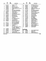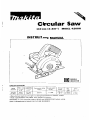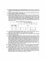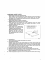
1
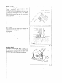
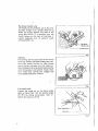
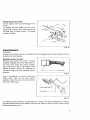
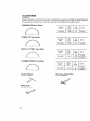
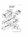
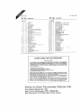
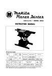
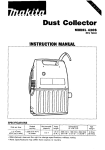
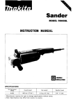
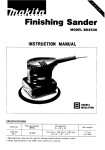
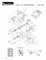
4-3/8"(I 1Omm) C IRCULAR SAW
WIRING D I A G R A M S
IMPORTANT!
To assure product
SAFETY and RELIABILITY, repairs,
maintenanceoradjustments should
be performed by
MAKITA
Service
Centers or other
qualified service
organizations. Always use MAKITA
replacement parts.
08-99
Model 4200H
Part
Fig.
No.
1
2
3
4
5
7
8
9
10
11
12
14
15
16
17
18
19
20
22
23
414372-1
651215-8
159898-3
643600-9
191945-4
953106-2
911261-6
911146-6
682504-0
664013-1
687052-4
911131-9
343289-0
961004-6
226419-7
213407-3
211056-0
253768-9
254002-0
516291-8
24
25
26
27
28
681613-2
211033-2
253192-6
213255-0
522806-1
29
30
31
32
33
34
911285-2
263002-9
150632-4
912121-5
262502-6
251247-1
2 Model4200H
atv.
Used
1
1
1
1
1
1
1
1
1
1
1
1
1
1
1
1
1
1
1
1
Part
Description
HANDLE COVER
SWITCH
MOTOR HOUSING
BRUSH HOLDER CAP
CARBON BRUSH SET CB-124
RIVET
PAN HEAD SCREW M5X40
PAN HEAD SCREW M4X25
CORD GUARD
CORD (2xI8x8;SJT)
STRAIN RELIEF
PAN HEAD SCREW M4X18
BAFFLE PLATE
RETAINING RING
HELICAL GEAR 19
O-RING 26
BALL BEARING 629LLB
FIAT WASHER 9
WOODRUFF KEY 3
ARMATUREASS’Y 115V
(Incl. Figs. 19,20,24,25)
INSULATlON WASHER
BALL BEARING 608LB
FLATWASHER 14
O-RING 18
FIELDASS’Y 115V
(Incl. Garter Spring 654158-3;
Connector 654502-4)
PAN HEAD SCREW M5X60
RUBBER PIN 4
BLADE CASE COMPLETE
C. S.H. SCREW M4X14
RUBBER BUSH
PAN HEAD SCREW M6X20
Fig.
35
36
37
39
40
41
42
43
44
45
46
47
48
49
50
51
52
53
54
55
56
57
58
59
60
61
62
No.
254001-2
265226-3
224081-2
224080-4
2858 15-8
321 197-5
21 1129-9
961155-5
164473-2
91 1103-4
231773-6
934301-3
941151-9
95 12 19-3
251919-8
251919-8
168158-2
265724-7
942151-2
934301-3
942151-2
315117-9
961052-5
226420-2
212046-6
159648-6
265883-7
ACCESSORIES
400
A-90093
401
164095-8
402
781011-1
403
782209-3
Qty.
Used
1
1
1
1
1
1
1
1
1
1
1
1
1
1
1
1
1
1
1
1
Description
1
1
1
1
1
1
WOODRUFF KEY 4
H. F. HEAD BOLT M6X17
OUTER FLANGE 36
INNER FLANGE 36
BEARING RETAINER 19-33
SPINDLE
BALL BEARING 602DDW
RETAINING RING S-38
SAFETY COVER
PAN HEAD SCREW M4X6
TENSION SPRING 4
WING NUT M6
FLAT WASHER 6
SPRING PIN 6-32
BOLT M6X20
BOLT M6X20
BASEASSEMBLY
WING BOLT M5X10
SPRING WASHER 6
WING NUT M6
SPRING WASHER 6
BEARING BOX
RETAINING RING S-12
HELICAL GEAR 41
NEEDLE BEARING 810
GEAR HOUSING
SCREW M5X6
1
1
1
1
4-3/8 CARBIDE BLADE
GUIDE RULE
WRENCH 22
SOCKET WRENCH 9
1
08-99
Circular Saw
118 mm (4-3/8") MODEL 4200H
INSTRUCTION MANUAL
.___-
DOUBLE
INSULATION
!
I
t
Blads
diameter
at
cutt'ng
llOmm
32"
4 5 ~
Power
Continuous rating
(IIIpUtl
No load speed
IRPMl
Overall
length
Net
welght
supply curd
860 W
l,ooo
230mm
3.0 kg
16 6 Ibsl
2 5 111
18 2 11 I
~~
14-3/8"1
11-114")
21mm
13/4"1
19")
~..
lMPORTANT
SAFETY INSTRUCTIONS
(For All Tools)
WARNING: WHEN USING ELECTRIC TOOLS, BASIC SAFETY
PRECAUTIONS SHOULD ALWAYS BE FOLLOWED TO REDUCE
THE RISK OF FIRE, ELECTRIC SHOCK, AND PERSONAL
INJURY, INCLUDING THE FOLLOWING:
READ ALL INSTRUCTIONS.
1. KEEP WORK AREA CLEAN. Cluttered areas and benches invite injuries
2. CONSIDER WORK AREA ENVIRONMENT. Don't use powei tools in damp
or wet locations. Keep work area well lit. Don't expose power tools to rain.
Don't use tool in presence of flammable liquids or gases.
3. KEEP CHILDREN AWAY. All visitors should be kept away from work area.
Don't let visitors contact tool or extension cord.
4. STORE IDLE TOOLS. When not in use, tools should be stored in dry, and high
or locked-up place - out of reach of children.
5. DON'T FORCE TOOL. I t will do the job better and safer at the rate for which
i t was intended.
'5:
6. USE RIGHT TOOL. Don't force small tool or attachment t o do the job of a
heavy-duty tool. Don't use tool for purpose not intended; for example, don't
use circular saw for cutting tree limbs or logs.
7. DRESS PROPERLY. Don't wear loose clothing or jewelry. They can be caught
in moving parts. Rubber gloves and non-skid footwear are recommended
when working outdoors. Wear protective hair covering to contain long hair.
8. USE SAFETY GLASSES. Also use face or dust mask if cutting operation is
dusty.
9. DON'T ABUSE CORD. Never carry tool by cord or yank it to disconnect from
receptacle. Keep cord from heat, oil, and sharp edges.
10. SECURE WORK. Use clamps or a vise to hold work. It's safer than using
your hand and it frees both hands t o operate tool.
11. DON'T OVERREACH. Keep proper footing and balance at all times.
12. MAINTAIN TOOLS WITH CARE. Keep tools sharp and clean for better and
safer performance. Follow instructions for lubricating and changing accessories. Inspect tool cords periodically and if damaged, have repaired by authorized service facility. Inspect extension cords periodically and replace if
damaged. Keep handles dry, clean, and free from oil and grease.
13. DISCONNECT TOOLS. When not in use, before servicing, and when changing accessories, such as blades, bits, cutters.
2
+
0 - 25
’
I
Total Length of Cord in Feet
26
50 [-
0
- - 6
6
10
12
16
10
12
-
kL
101 - 150
~-
Ampere Rating
More
Not More
Than
Than
A W G
18
18
16
14
16
16
16
12
16
14
14
12
14
12
Not Recommended
I
VOLTAGE WARNING: Before connecting the tool t o a power source (receptacle,
outlet, etc.) be sure the voltage supplied is the same as that specified o n the
nameplate of the tool. A power source with voltage greater t h a n that specified
for the t o o l c a n result in SERIOUS INJURY t o the user - as well as damage t o
the tool. If in doubt, DO NOT PLUG IN THE TOOL. Using a p o w e r source with
voltage less t h a n t h e nameplate rating is harmful t o the motor.
ADDITIONAL SAFETY RULES
1. Keep Guards In Place and In Working Order.
Never wedge or tie lower guard open. Check operation of lower guard before
each use. Don't use if lower guard does n o t close briskly over saw blade.
CAUTION: If saw is dropped, lower guard may be bent, restricting full return.
2. Keep Blades Clean and Sharp.
Sharp blades minimize stalling and kickback.
3. DANGER: Keep Hands Away From Cutting Area.
Keep hands away f r o m blades. Don't reach underneath work whilz blade
is rotating. Don't attempt t o remove cut material when blade is nioviny.
CAUTION: Blades coast after turn off.
4. Support Large Panels.
Large panels must b e supported as
shown in Fig. 1 t o minimize the risk
of blade pinching and kickback.
When cutting operation requires the
resting of the saw on the work
piece, the saw shall be rested on
the larger portion and the smaller
piece cut off.
A TYPICAL ILLUSTRATION OF
SUPPORT LARGE PANELS TO
AVOID KICKBACK SUPPORT
1HE PANEL NEAR THE CUI
I
Fig.
5. Use Rip Fence.
Always use'a fence or straight edge guide when ripping.
6. Guard Against Kickback.
Kickback occurs when the saw stalls rapidly and is driven back towards the
operator. Release switch immediately if blade binds or s a w stalls. Keep blades
sharp. Support large panels as shown in Fig. 1. Use fence or straight edge guide
when ripping. Don't force tool. Stay alert exercise control. Don't remove saw
from work during a cut while the blade is moving.
7. Lower Guard. Raise lower guard with the retracting handle.
8. Adjustments. Before cutting be sure depth and bevel adjustments are tight.
9. Use Only Correct Blades In Mounting. Don't use blades with incorrect size holes
Never use defective or incorrect blade washers or bolts.
#
I O . Avoid Cutting Nails. Inspect for and remove all nails from lumber before cutting.
5
11. When operating the saw, keep the
cord away from the cutting area and
position it so that it will not be
caught on the workpiece during the
cutting operation.
Operate with proper hand support,
proper w o r k support, and supply
cord routing away f r o m the w o r k
area.
A TYPICAL ILLUSTRATION OF
PROPER SUPPORT, AND SUPPLY
CORD ROUTING.
I
Fig. ;
WARNING:
It is important t o support the work properly and t o hold the saw firmly t o prevent loss of control which could cause personal injury. Fig. 2 illustrates typical
hand support of the saw.
12. Never attempt t o saw with the circular saw held upside d o w n in a
vise. This can lead t o serious accidents, because it is extremely dangerous.
13. Before setting the tool down after completing a cut, be sure that the lower (telescoping) guard has closed and the blade has come t o a complete stop.
SAVE THESE INSTRUCTIONS.
6
Top guide
t h e shorter slot (as seen from right) IS lor
bevel cuts of 4 5 degrees Align i t wllh your
suttiiig line
Topguide -
~
Fig. 5
utting depth
J adjust the cutting depth. loosen the
lumb screw on the depth guide. then.
slding down the base with one hand, raise
' lower the body for the desired depth
J
Fig. 6
7
R i p fence (Guide rule)
The handy rip lence allows you IO do extraaccurate straight cuts Simply slide Ihe rip
fence up snugly against the side 01 the
stock and secure 11 in posilion with the
Ihumb screw on Ihe front of the base I1
makes repeated cuts of uniform stock
width possible. too
Thumb screw
Fia. 7
Sawing
For sawing. set the base plale on the wood
to be CUI without the blade making any con
lac1 Then switch the saw on Now simply
move the saw forward over the wood surface keeping i t llat and advancing smoothly
until the sawing is completed To get clean
CUIS
keep your sawing line straight and
your speed of advance uniform
a.
Fig. 8
1
For bevel work
Loosen the wing nut on the bevel scale
plate on base front. Set for desired angle
(0'-45'1 by tilting accsrdingly. then retighten the wing nut firmly.
\
\
\A
Bevel scak plaie _J
Wmg nul
-\
\
Fig. 9
x
Replacing the saw blade
Do not replace with saw blade bigger than
4-310'' .
To replace the saw blade, grip the outer
flange with a wrench (22). then remove the
hex bolt with a socket wrench. The blade
comes off easily.
Fig. 10
MAINTENANCE
CAUTION:
Always be sure that the tool is switched off and unplugged before attempting to perform
inspection or maintenance
Replacing carbon brushes
Remove and' check the carbon brushes
regularly. Replace when they wear down to
the limit mark. Keep the carbon brushes
clean and free to slip in the holders Both
carbon brushes should be replaced at
the same time, Use only identical carbon
brushes
*'
L
A
Limit mark
Fig. 11
Use a screwdriver to remove the brush
holder caps. Take out the worn carbon
brushes, insert the new ones and secure
the brush holder caps.
Brush holder cap
Screwdriver
Fig. 12
To maintain product SAFETY and RELIABILITY, repairs. any other maintenance or adjustment should be performed by Makita Authorized or Factory Service Centers, always using
Makita replacement parts
9
ACCESSORIES
CAUTION.
These accessories or attachments are recommended for use with your Makita tool specified in this
manual. The use of any other accessories or attachments might present a risk of injury to persons.
The accessories or attachments should be used only in the proper and intended mannei.
COMBINATION Saw Blade
11014-3/8'1
I
20(3/4")
I
50
I 721104-2
CROSS-CUT Saw Blade
~~
Diameter
No
diameter
lmml
110 (4-3/8'1
20 13/4")
teeth
Part No
60
721 1050
L-rL--.J
METAL CUlTING Sew Blade
Diameter
11014-3/8')
diameter
I
(mml
Part No
-1
2013/4")
7211084
CARBIDE-TIPPED Saw Blade
Diameter
110 l4-3/8')
S o c k e t Wrench
Part No 782209-3
Wrench 22
Pait No 78101 1-1
"ole
dlanieter
lmml
20 13/4")
Rip F e n c e (Guide Rule)
Part No 164095-8
Part No.
4
7211076
12
A-90093
110 mm (4-3/8"1
CIRCULAR SAW
Model 4200H
Note: The switch and other part conflguratlons
may differ from country to country.
11
Me
It
,
31
1
I
I
32
33
4
3
4
2
34
5
6
7
2
1
35
38
39
1
2
B
2
3
9
1
IO
I
1
37
40
4,
Cord Guard
COR0 ASSEMBLY
42
13
41
?
I
5
16
I
2
I
46
I
47
I1
1
18
19
I
I
I
1
I
48
49
50
20
21
22
a5
51
52
53
54
23
24
25
26
27
I
18
I
29
2
30
__
55
56
51
58
Inrulswn Washer
Ball Bearing 608LLB
F Warher 14
0 Ring I8
FIELO ASSEMBLY
H Bolt M5r60 lWilli WailiirI
Rubber PIIS4
8
I
I
1
1
1
1
1
I
I
1
1
I
I
1
I
I
I
I
I
3
1
1
59
60
1
1
I
I
61
I
-
Wade Case
c. H Screw M4.14 IWilh Washer1
R"bb*, 0"
MAKITA LIMITED ONE YEAR WARRANTY
W.ur.inty
Policy
Makita do Brasil Ferramentas Eletricas Ltda.
R u a Makita Brasil, No. 200
Bairro Dos Alvarengas, CEP: 09852-070
SBo Bernard0 Do Campo-SBo Paulo, Brasil