1
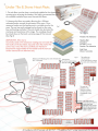
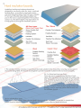
V0215
Heating.
For Use Under
· Tiles
St e
Wood
in ate
I.
STRUCTIONS
Welcome to Roma Heating,
the underfloor heating specialists.
Roma Underfloor Heating systems are suitable for use under virtually any type of floor covering. All Roma
Heating systems are suitable for use as a primary heat source, no radiators required or for just floor warming.
(This assumes sufficient coverage and insulation is installed.) For further information on all underfloor heating
systems and ancillary products please ask your supplier or visit our website: www.romaheating.co.uk
• Page 1 + 2, Index & Q&A
• Page 3 + 4, Under Tile & Stone Loose Wire Heating Cables.
• Page 5 + 6 , Under Tile & Stone Heat Mats 150w + 200w/sqm.
• Page 7 + 8, Under Wood & Laminate 150w/sqm Foil Heat Mats.
• Page 9 + 10, Under Wood , Laminate & Carpet 200w/sqm Heat Film Mats.
• Page 11 + 12, In Screed Heating Cable.
• Page 13 + 14, Hard Insulation boards.
• Page 15 + 16, Tile Backer Insulation boards.
• Page 17 + 18, Impact Plus Insulation & Duo Overlay
Thermostats
All our thermostats are suitable for use with all our underfloor heating systems. All three thermostat options are rated
at 16amps which will allows the units to control 3600watts without the need of any additional switching.
If over 16amps/3600wa tts of heating is being installed, either additional thermostats or a relay switch, (sometimes
known as a contactor) should be installed to carry the load.
Colour Touch Screen Thermostat.
Digital Thermostat.
1440MON
,,
...
All Installation MUST comply wit BS 7671 - 171 a
Manual Thermostat .
2
Frequently Asked Questions.
Can I use this as a primary heat source; do I still need radiators?
All our underfloor heating systems have been designed to be suitable for use as the primary heat source (no
radiators required). This is providing you install a minimum of 150w/ m2 system over 70%+ of the floor area. Also the
floor and room must have suitable insulation levels which will then mean no additional heating will be required .
Can I cut the cable or mat if I have too much?
When considering what size system you require it is important not to over order as the heating cannot be cut down
to fit. A good rule of thumb is to order approximately 80% of the total floor area. This will allow you to easily fit the
heating system leaving only a small unheated border around the room edge. The heating cable must never be cut or
reduced in length .
Subfloor Construction
Heat up Time
Plywood
35 minutes
Plywood+ lOmm HIB
15 minutes
75mm Insulated
Concrete in Screed
2 - 4 Hours
Un-insulated Concrete
2 - 8 Hours
Concrete+ lOmm HIB
20 minutes
Do I need insulation? How long will it take to warm up?
Although not a necessity over wood, sub floor insulation
will still greatly increase the response rate and overall
efficiency of all underfloor heating systems. When installing
heating over a concrete subfloor we highly recommend the
use of a suitable insulation as un-insulated concrete will
drain the heat from the heating system. The table opposite
shows some approximate timing 's.
Is underfloor heating expensive to run?
Underfloor heating is the most efficient way to heat an area
due to the even heat distribution from the floor up . This helps to keep the heat at a low, effective and usable level.
Studies have shown that when a person 's feet are warm they perceive the environment to be warmer than when
their feet are cold. Because of this the ambient temperature of the room can then be lowered without the person
feeling cold which reduces the running cost of the heating but still providing the occupant with a more consistent and
comfortable heat distribution.
Can I fit the heating and will it require maintenance?
Electric underfloor heating does not require any specialist labour or equipment to install or maintain the system,
(other than a qualified electrician to make the final connections to the mains power). With a little patience and
common sense most competent DIY enthusiasts would be able to install our underfloor heating systems with ease.
Unlike other forms of heating, electric underfloor heating requires no maintenance once installed. With no moving
parts, no excessive heats or leaks to consider once installed and protected by the floor covering our underfloor
heating can provide a lifetime of hassle free heating .
How do you control the heating?
All our underfloor heating systems should be controlled with a suitable thermostat. There are various thermostat options but all options control the heating through the same principle . Mains 220/240v power is fed through the thermostat to the heating system as and when needed . The user will set a desired temperature and the thermostat will
switch the power on and off accordingly to the heating system as and when needed to achieve and maintain the set
temperature .
3
Loose Wire Under Tile & Stone Heating Cable.
l: The sub floor must be clean, sound and suitable for the chosen floor cove
prior
to laying the heating. We highly recommend the use of a suitable insulatio layer
over concrete and uninsulated sub floors.
2: Measure the floor accurately allowing for a lOOmm+ unheated border a
the perimeter of the area. Once measured make sure the heating cable is
suitably sized for the area to be heated. Typically most domestic loose wire
systems (depending upon your requirements) will be fitted with
2
140w-200w/m . To work out your floor/system wattage, simply
2
divide the heating system total wattage by the total floor area m
to be heated. The end figure should ideally be between
2
140 - 200w/m . The length of the cable and total system wattage can be
found on the outer box's/cable spools
Flexible Tile Adhesive
Heating System
Insulation
(seepage13& 14)
/
Flexible Tile Adhesive
Sub Floor
Wood I Concrete
3: Before the cable is unrolled it must be tested for
continuity and resistance. Mark this reading down
the back warranty page of this manual.
(See Fig 2)
(IMPORTANT, If the cable is incorrectly sized or the
resistance readings do not match the test results on
the box label, stop and return for the correct size.
Once the cable is unrolled over the floor it
becomes the responsibility of the installer and the
cable can not be returned for an alternate size).
:""
Ty pi cal Loose W ire Flo o r Layout Fo r Kitchen Ty pe Area.
Fig 3
Floor Prob e
Heating Cabl e
4: Using the figures worked out in stage 2, the
spacing's between cable runs are worked out by:
Fixing Tape
A: Divide 1000 by the length (meters) of the
heating cable.
B: Multiply result A by the size of the area you are
heating in m .
The final figure is the spacing in mm the cables
should be spaced out at. Please note the figure
should be somewhere between 50 - 80mm. This
figure is a guide and small adjustments may be
required to the final spacings to achieve the best
coverage. The cable must NOT be cut or reduced
in length. The spacings between cables are either
increased to increase the heated area, or reduced
to reduce the heated area. Only the black cold/ connection ends can be reduced or lengthened if required.
All Installation MUST comply wit BS 7671 - 171 a
4
5: Before the cable is unrolled and fitted it is advisable to mark the floor accurately using the results from stage 4
showing precisely where the heating cable is to be laid. This will allow the installer to accurately design the floor
layout to best use the available cable making sure to keep even spacings between cable runs. (See Fig 3)
6: If possible start laying the cable working away from the thermostat location. Using small tabs of fixing tape,
accurately lay the cable. It is un-advisable to cover the entire cable with fixing tape as this can affect the
performance of subsequent adhesives to adhere sufficiently to the sub floor. The tape is only required to maintain a
consistent spacing between cable runs until the levelling/a dhesive is applied over. It is important that cables are not
laid too close together. A minimum of 50mm should be maintained between cable runs. If the heating cable is set to
close, touch or overlapped at any point the cable may overheat.
7: Once the heating is fitted the inulation resistance and electrical continuity test should be repeated and noted
down on the warranty page. Make sure these readings are the same as the readings noted down during stage 2.
The heating should also be tested and results recorded after the flooring has been fitted. There is no limit to how
much the cable can be tested but to complete the warranty the heating must be tested before it is laid, after being
laid and after the floor covering has been installed. All figures must be accurately recorded. (See Fig 2)
8: The floor probe supplied with the thermostat should now be
fitted . The probe must be installed between 2 heating wires but
no more than 30mm away from one cable. Make sure when
fitting the probe no other heating or cooling sources can
influence the floor probe such as hot water pipes. Once the
probe is fitted a resistance check should be carried out to
confirm the probe is fully functional and the readings noted
down on the warranty card. (See Fig 4)
Fig 5
Fig 4
Thermostat
Load
(Heating Cable/s)
Dual Core
Spur
Underfloor Heating
Systems
Single Core
3 Core Coble
ie: Tw in & Earth
Thermostat
Location
3CoreCoble
ie: Twin & Eorlh
9: If multiple cables need to be installed, all
cables, (only of the same type) can then be
connected together into a suitable junction box . A
single suitable spur can then be taken from this
ready to be wired in . Depending upon the total
load additional switching may be required to
switch large areas/ loads . (See Fig 5)
10: The heating system must be run via a residual
current device (RCD), fitted in accordance with all
current electrical regulations at time of installation.
All electrical connections should be carried out by
a qualified electrician. It is the installer/electrician 's
responsibility to make sure the system is fitted
correctly and any additional materials are suitable
for use with the heating system installed .
any particu or oca electrical regulations .
5
Under Tile & Stone Heat Mats.
l: The sub floor must be clean , sound and suitable for the chose
covering prior to laying the heating. We highly recommend the
of a suitable insulation layer over concrete sub floors.
2: Measure the floor accurately allowing for a lOOmm+
unheated border around the perimeter of the area. Once
measured make sure the heating mat is a suitable size for the
area. The mat size and wattage can be found on the outer
box and heating mat label. The mat should also be tested for
continuity and resistance at this stage. The readings should
be noted down on the back warranty page of this manual.
(See Fig 2)
Fig l
Flexible Tile Adhesive
(IMPORTANT, If the mat is
incorrectly sized or the resistance readings do not match the
test results on the box label, stop and return the mat for the
correct size. Once the mat is unrolled over the floor it
becomes the responsibility of the installer and the mat can
not be returned for an alternate size).
Heating Mat
Insulation
(see page 13 & 14)
Flexible Tile Adhesive
Sub Floor
Wood I Concrete
Fig 3
Fig 2
Make Sure All Readings Are within 5% between
Use Sc issors
Box/ Multimeter
to cu t e mes
ac
The cable mat
can be tu rned
in any d irection by cutting
the mesh and rotating the
roll
The mat can
con tinue to be
rolled out making
sure the mat is not
overlapped at any
point.
The cable can be
removed from mesh to
cover small and
awkward areas. Small
tabs of tape should be
used to hold the loose
cable in place.
Fixed
Obstacle
All Installation MUST comply wit BS 7671 - 171 a
6
3: Start the heating close to the thermostat location if possible. If this is impractical the cold tail can be easily
extended or shortened with a suitable electrical wire. Slowly unroll the mat pealing the adhesive backing tape on
the mat off as you proceed. The mat must be firmly pressed onto the floor making sure the heating element is not
twisted or stressed at any point.
4: To turn the mat in any direction or return it back on itself the installer can cut through the mesh backing , (DO NOT
CUT THE HEATING CABLE) to allow the mat to be redirected in any direction. (See Fig 3)
5: Alternatively if the area to be covered is an irregular shape or an obstacle has to be avoided the heating cable
can be detached from the mesh backing and laid loose . This will allow the cable to be laid in any direction and a
suitable fixing tape can then be used to hold the cable in position ready for the subsequent floor covering to be
installed over. When laying the heating cable loose a consistent spacing between cable runs must be maintained ,
(the same spacing as when attached to the mesh backing) to achieve an even heat output across the floor. It is
important that cables are not laid to close together. A minimum of 50mm should be maintained between cable runs.
If the heating cables get too close , touch or overlap at any point the cable may overheat. (See Fig 3)
6: Once the heating is fitted the electrical resistance and continuity test should be repeated and noted down on the
warranty page. Make sure these readings are the same as the readings noted down during stage 2 . The heating
should also be tested after the flooring has been fitted. There is no limit to how much the cable can be tested but to
complete the warranty the heating must be tested before it is laid , after being laid and after the floor covering has
been installed . All figures must be accurately recorded.
7: The floor probe supplied with the thermostat should now be fitted . The probe must be installed between 2 heating
wires but no more than 30mm away from one cable. Make sure when fitting the probe no other heating or cooling
sources can influence the floor probe such as hot water pipes. Once the probe is fitted a resistance check should be
carried out to confirm the probe is fully functional and the readings noted down on the warranty card. (See Fig 4)
8: If multiple mats need to be installed , all mats , (only of the same type) can then be connected together into a
suitable junction box . A single suitable spur can then be taken from this ready to be wired in . Depending upon the
total load additional switching may be required to switch large areas / loads. (See Fig 5)
Fig 4
Mains
Live
AC230V
Thermostat
Sensor
Load
(Heating Cable/ s)
9: The heating system must be run via a residual
current device (RCD), fitted in accordance with all
current electrical regulations at time of installation . All
electrical connections should be carried out by a
qualified electrician. It is the installer/ electrician 's
responsibility to make sure the system is fitted correctly
and any additional materials are suitable for use with
the heating system installed.
Dual Care
Fig 5
Spur
Max30mm
3CoreCable
Thermostat Location
7
Under Laminate Wood Vinyl & Carpet Aluminium Foil Heating
l: The Sub floor must be clean , sound and suitable for the chosen
floor covering prior to laying the heating. Impact plus 6mm
lotion or hard insulation boards must then be installed over the
sub floor prior to fitting the heating, (see insulation fitting
instructions).
2: Measure the floor accurately allowing for a lOOmm+
unheated border around the perimeter of the area. Once
measured make sure the heating mat is a suitable size for the
area. The mat size and wattage can be found on the outer
box and heating mat. The mat should also be tested for
continuity and resistance at this stage. The readings should be
noted dow n on the back w arranty page of this manual. (See
Fig 2)
Fig 1
(IMPORTANT, If the mat is incorrectly sized or the resistance
readings do not match the test results on the box label ,
stop and return the mat for the correct size. Once the mat is
unrolled it becomes the responsibility of the installer and the
mat can not be returned for an alternate size).
Carpet I Vinyl
Wood
Overlay Duo
(For Use Under Carpet &
Vi nyl Flooring)
Heat Foil
Insulation
Sub Floor
Wood I Concrete
Fig 3
Fig 2
The cable mat
can be turned
in any direction by
cutting the mat and
rotating the roll
I) = Uncovered Heating
Cable, (Cover with
foil tape)
Use the aluminium tape
provided to cover both sides
of the mats and any exposed
wires to maintain the heat
distribution and full earthing
of the whole mat.
Ill
All Installation MUST comply wit BS 7671 - 171 a
8
3: Start the heating as close to the thermostat location as possible . If this is impractical the cold tail can be easily
extended with a suitable electrical wire. Slowly unroll the mat using the foil tape to hold the mat in place . All
exposed cables at the side of mats must be covered with the foil tape provided. As you proceed , the mat must be
laid flat making sure the heating element is not twisted or stressed at any point.
4: To turn the mat in any direction or turn it back on itself the installer can cut through the mesh/ foil backing , (DO
NOT CUT THE HEATING CABLE) to allow the mat to be redirected in any direction . (See Fig 3)
5: Alternatively if the area to be covered is an irregular shape or an obstacle has to be avoided the mat can be cut
several times into strips, (the cable must never be detached from its foil casing.) This will allow the thin strips of cable
enveloped in the foil to be laid in any direction. The foil tape must then be used to cover any exposed wire and join
all strips and mat runs together. Exposed wire can cause hot spots also disrupt the earthing continuity between
heating sections. It is important that cables are not laid to close together. A minimum of 50mm should be maintained
between cable runs. If the heating cables get too close , touch or overlap at any point the cable may overheat. (See
Fig 3)
6: Once the heating is fitted the electrical resistance and continuity test should be repeated and noted down on the
warranty page. Make sure these readings are the same as the readings noted down during stage 2. The heating
should also be tested after the flooring has been fitted. There is no limit to how much the cable can be tested but to
complete the warranty the heating must be tested before it is laid , after being laid and after the floor covering has
been installed . All figures must be accurately recorded.
7: The floor probe supplied with the thermostat must now be fitted . The probe must be installed under the foil and
between 2 heating wires but no more than 30mm away from one cable. Make sure when fitting the probe, no other
heating or cooling sources can influence the floor probe such as hot water pipes . Once the probe is fitted a
resistance check should be carried out to confirm the probe is fully functional and the readings noted down on the
warranty card, (See Fig 4) When heating wood or laminate the floor covering manufactures recommended max floor
temperature should be programed into the thermostat. The thermostat must also be set to regulate floor temperature
, not air temperature.
8:lf multiple mats need to be installed , all mats, (only of the same type) can then be connected together into a
suitable junction box . A single suitable spur can then be taken from this ready to be wired in. Depending upon the
total load additional switching may be required to switch large areas/ loads. (See Fig 5)
9: The heating system must be run via a residual current device (RCD), fitted in accordance with all current electrical
regulations at the time of installation . All electrical connections should be
carried out by a qualified electrician. It is the installer/ electrician's responsibility to make sure the system is fitted
correctly and any additional materials are suitable for use with the heating system installed.
Thermostat
Fig4
Mains
Live
AC230V
FigS
Sensor
Load
(Heating Cable/s)
Spur
3 Core Cable
ie: Twin & Earth
Thermostat Location
Placed Central between two cables
9
Under Wood Laminate Vinyl & Carpet Heat Film.
l: The sub floor must be clean, sound and suitable for the chosen floor covering prior to laying
the heating. 6mm impact plus thermal insulation or had insulation boards must be installed over
the sub floor prior to fitting the heating, (see insulation fitting instructions).
Please note the max tog rating for underlay is 0.8 tog and for carpet is 2 tog, (2.8 tog Total).
No additional coverings, flat bottom furniture or highly insulated objects such
as rugs, bean bags should be fitted over heated floor areas.
2: Before laying the heating the floor should be measured accurately and a
plan done to show where the individual mats are to be laid. All heat film
mats are made to the customer's measurements. If a proposed mat
layout was produced and agreed this can now be followed which
will show which mats are to be laid in which areas. If a proposed
mat layout was not agreed the mat sizes would have
been produced according to the customers stated
mat sizes. (See Fig 2)
3: Once the mat layout has been determined
the mats must be tested for continuity and
resistance at this stage. The readings must be
checked off and noted down on the back of the
warranty page of this manual. All readings must
be within tolerance.
(IMPORTANT, Once the mat is unrolled and
taped to the floor it becomes the responsibility
of the installer and the mat can not be returned
for an alternate size).
Wood I Laminate
Impact Pluss In sulation
Sub Floor
Wood I Concrete
Fig 2
4: The floor probe supplied with the thermostat should
now be fitted. The probe must be installed directly
under an area that will have a heat mat laid over. The
probe must be scored into the floor/insulation and
taped in place, leaving it flush with the insulation. The
end of the probe should not be covered. Make sure
when fitting the probe no other heating or cooling
sources can influence the floor probe such as hot
water pipes. Once the probe is fitted a resistance
check should be carried out to
confirm the probe is fully functional and the readings
noted down on the warranty card. (See Fig 2 +4)
5: Lay the heating mats over the insulation COPPER BAR DOWN, making
sure the mats do not overlap at any point. Tape can be used on the ends
and edges to hold the mats in place. All cold tails and connection points to
the heating mats must be scored into the insulation and taped over which
will leave a flat level floor layer for the floor covering to be
installed over.
6: The mats must always be connected in parallel, NOT series. If multiple mats are used, it is recommended to run
all the cold connection wires back to one point. This will allow the installer at a later date to join all live wires
together and all neutral wires together in a suitable junction box. One spur can then be taken from the junction box
to the thermostat. (See Fig 3)
All Installation MUST comply wit BS 7671 - 171 a
10
Thermostat
Non Heating Wires
7: Once oll the heating mats
have been laid in place the
vapour barrier can be fitted over. The
vapour barrier does not have to cover
the entire area only the heat mats
themselves . Please note every l meter
of vapour barrier folds out to be 4m in
width. This like the heating mats can
be held in place with the tape provided. (See Fig 4) Thermostat
If the final flooring is not to be fitted for some time
the heat mats should be protected from damage with
a suitable protective layer .
Fig 3
Junction box
Non Heating Wires
Thermostat
Heat Mats
Tabs of tape
Impact Plus Insulation
Fig 4
Resistance Check .
To check heat film mat resistance
in Ohms (0) please follow the
equation below
250.;. SQM (of mat) x 0.95 = O+ /-10%
our Barrier The reading must be within 10%, if not
test the mat again or call technical for
assistance.
The cold tails on each mat
can be extended or shortened
on site please consult your
electrician as this will
depend on mat layout and
total heating load.
8: Once all the mats have been installed
they must be retested, See step 3. The
heating is now ready to have the final floor
covering installed over. The heating must also be
tested after the flooring has been fitted. There is no limit to
how much the heating can be tested but to complete the warranty the heating must be tested before it is laid, after
being laid and after the floor covering has been installed. All figures must be accurately recorded. Depending upon
the total load additional switching may be required to switch large areas/ loads .
9: Before the heating is turned on, the floor manufacturer's max recommended floor temperature must be
programmed into the thermostat. The thermostat installed must have a max default floor temperature setting and the
thermostat must be set to regulate floor temperature only via a suitable floor probe / probes, (never run the
thermostat on air temperature). If floor temperature is not regulated correctly, some floor coverings can be
overheated and damaged. Please refer to your thermostat instructions for max floor temperature settings.
11
In Screed Heating Cable, (for all floor
l: The Sub floor must be insulated with a suitable insulation,
clean, sound and made ready to receive the screed covering
prior to the heating cable being installed.
2: Measure the floor accurately allowing for a lOOmm+
unheated border around the perimeter of the area. Once
measured make sure the heating cable is suitably sized for the
area to be heated. Typically most domestic in screed floors
(depending upon your requirements) will be fitted with
2
160w-220w/m . To work out your floor/system wattage,
simply divide the heating systems total wattage by
the total floor area to be heated in m2 . The
2
end figure should be between 160 - 220w/m .
The length of the cable and total wattage can be
found on the outer box or heating cable.
Up to 75mm screed
In screed Cable
Insulation
Fig 2
Sub floor
Make Sure All Readings Are wi thin 5% off
Box/ M ultimeter
3: Before the cable is unrolled it must e tested for continuity an resistance . Mark this reading down on the back
warranty page of this manual (See Fig 2)
(IMPORTANT, If the cable 1s incorrectly sized or the resistance readings do not match the test results on the box label ,
stop and return for the correct size. Once the cable is unrolled it becomes the responsibility of the installer and the
cable can not be returned for an alternate size).
4: Using the figures worked out in stage 2, the
spacing's between cable runs are worked out by:
A: Divide 1000 by the length (meters) of the heating
Fig 3
Typical In Screed Floor Layout For Kitchen Type Area.
Floor Probe
cable.
B: Times result A by the size of the area you are
heating in m2 . The final figure is the spacing in mm
the cables should be spaced out at.
Please note the figure should be somewhere
between 70 - llOmm . This figure is a guide and
small adjustments may be required to the final
spacing's to achieve the best coverage. The cable
must NOT be cut or reduced in length. The spacing's
between cables are either increased to increase the
heated area, or reduced to reduce the heated area,
(the black cold/connection ends can be reduced or
lengthened if required). (See Fig 3)
All Installation MUST comply wit BS 7671 - 171 a
Heating Cable
Tape or Clips
12
5: Before the cable is unrolled and fitted it is advised to mark the floor accurately showing precisely where the
heating cable is to be laid. This will allow the installer to accurately design the floor layout to best use the available
cable making sure to keep even spacing's between cable runs. (See Fig 3)
6: If possible start laying the cable working away from the thermostat location using small tabs of fixing tape or
fixing clips to accurately lay the cable. It is inadvisable to cover the entire cable with fixing tape as this will affect the
screeds ability to fully envelope the cable. The tape is only required to maintain a consistent spacing between cable
runs to achieve an even floor covering until the screed is applied over. It is important that cables are not laid too
close together. A minimum of 50mm should be maintained between cable runs. If the heating cable is set too close,
touch or overlap at any point the cable may overheat.
7: Once the heating is fitted the electrical resistance and continuity test should be repeated and noted down on the
warranty page. Make sure these readings are the same as the readings noted down during stage 2. The heating
should also be tested after the screed has been laid. There is no limit to how much the cable can be tested but to
complete the warranty the heating must be tested before it is laid, after being laid and after the covering screed has
been installed. All figures must be accurately recorded.
8: The floor probe supplied with the
thermostat should now be fitted. The probe must be
installed between 2 heating wires but no more than
30mm away from one cable. Make sure when fitting the
Fig 4
probe no other heating or cooling sources can influence
the floor probe such as hot water pipes. Once the probe
is fitted a resistance check should be carried out to
.
Mains
confirm the probe is fully functional and the readings
noted down on the warranty card. (See Fig 5)
Live Feed
AC230V
Fig 5
Thermostat
Sensor
Load
(Heating Cable/s)
Underfloor Heating
Systems
Max30mm
3 Core Cable
ie: Twin & Earth
Thermostat Location
9: If multiple cables need to be installed, all cables, (only of
the same type) can then be connected together into a suitable junction box. A single suitable spur can then be taken
from this ready to be wired in. Depending upon the total
load additional switching may be required to switch large
areas/ loads. (See Fig 5)
10: The heating system is now ready to have either, flexible
20-75mm self leveling compound or screed installed over in
accordance with the adhesive manufactures instructions. The heating must be run via a residual current device (RCD)
and connected to the mains power in accordance with all current electrical regulations at time of installation. All
electrical connection should be carried out by a qualified electrician. It is the installer/electrician ' s responsibility to
make sure the system is fitted correctly and any additional materials are suitable for use with the heating system installed.
13
Hard insulation boards.
Underfloor hard thermal insulation boards are
designed for use directly under tile, stone, wood and
laminate floors. It can also be used under mosaic,
vinyl and carpet flooring but must first have a suitable
9+mm layer of flexible self levelling installed over
prior to the vinyl or carpet being fitted. The insulation
comes in 6 , 10 & 20mm depths. The steps below are
to help guide you through the installation process.
All floor types
(Wood, Vinyl, Carpet, Tiles )
9mm+ Flexible Self
Levelling
Heating System
Insulation
Insulation
Flexible Tile Adhesive
Sub Floor
Wood I Concrete
Sub Floor
Wood I Concrete
Carpet I Vinyl
____ _ _ _ Suitable Heating
System
Insulation
_ _ _ Sub Floor
Wood I Concrete
Overlay Duo
Suitable Heating
System
Insulation
Sub Floor
l: The sub floor whether concrete or wood should be made suitable for the chosen floor covering, (ie tiles) prior to
any boards being fit d The boards are designed to provide increased insulation levels not structural rigidity.
28: For all other floor types.
Make sure the floor ·
e, clean, dust and debris
as only then the boards can be laid. A suitable floor
primer should be applied to provide a good fix for the a
sive (see adhesive fitting instructions).
All Installation MUST comply wit BS 7671 - 171 a
14
3: Using a standard l part flexible floor tile adhesive, suitable for use with the sub floor construction, (ie wood or
concrete) spread a thin full bed of adhesive over the floor. It is advisable to work in board size areas at a time and
rather than using a typical floor tiling trowel , to use a smaller notched trowel such as a 6mm notch size which will
increase the coverage of adhesive per bag.
4: Once the adhesive is spread lay the insulation boards over the freshly spread adhesive using a large, rigid, flat
trowel/board to press the insulation boards down flat into/onto the adhesive. Care should be taken to make sure
the boards are fully pressed into the adhesive and no air pockets or gaps are left under the boards. All boards
should be butted tightly together making sure to achieve a full floor coverage. It is good practice to stagger joints
between boards and if necessary the flexible floor adhesive can be used to fill any small gaps between boards.
5: If boards need to be cut to size this is easily done with
6: Once the boards are laid and the adhesiv
set, care should be taken not to apply excessive point loads to the
insulation until the tiles or levelling has been installed . Small dents and damage caused to the surface of the boards
are quite normal and of no concern. If however the boards are to be left exposed for long periods of time or other
work is to be carried out over the boards they should be covered with sheets of ply or other hard sheet material to
minimise the chance of damage.
7: It is advisable to fit the final floor covering as soon as possible once the insulation has been installed. When fitting
the chosen final floor covering it is advisable to work on top of a hard board . This will help prevent damage to the
insulation when the work is being carried out.
SA: Wood and laminate flooring . (If not following step 2A)
Both under floor heating and wood type tongue and grove flooring can now be fitted directly over the insulation in
accordance with the manufactures fitting instructions.
SB: Tile & Stone Flooring
Tiles measuring 150xl50mm or bigger can be fitted directly over the insulation . A suitable flexible tile adhesive
should be used as directed by the adhesive manufacture . The tiling should be carried out in the normal way making
sure to fit the tiles with a full bed of adhesive, (never dot and dab tiles).
SC: Fitting vinyl, carpet or mosaics.
When fitting non interlocking rigid sheet material over the insulation boards an 9+mm layer of flexible levelling
compound should first be fitted over the insulation. This will provide protection from high point loads as it will spread
the weight over the insulation surface allowing the subsequent layers to be fitted . The levelling should be fitted in
accordance with the manufacturer's instructions.
15
Cementatious Tile Backer Boards. (Wall and Floor Boards)
Cementatious tile backer boards are designed to insulate and
water proof walls and floors. Ideal for wet room installations,
the boards can be used directly under tile,
stone, wood and laminate floors.
It can also be used under mosaic, vinyl
and carpet flooring but must first have a
9+mm layer of flexible self levelling
installed over prior to the vinyl or carpet
being fitted. The insulation comes in 6, 10
& 20mm depths. The steps below are listed to help
guide you through the installation process.
lA: If you are fitting tile backer board to
a floor loosely or with tile adhesive
please follow the instructions on
page 13 -14
(Hard insulation boards)
18: If you are screwing the boards in
place or tanking a room please follow
the instructions below.
2: The sub floor or walls whether
concrete, wood or plasterboard should
be made suitable for the chosen floor
covering, (ie tiles) prior to any boards
fitted. The boards are designed to provide in
insulation levels not structural rigidity.
Tile
Flexible Tile Adhesive
Heating Mat I Cable
Cementatious Insulation
Flexible Adhesive
Sub Floor
Wood I Concrete
3: Tile backer boards can be screwed to walls and
floors using suitable fixing discs and screws. The discs
must be located at 300mm centres or closer,
(minimum 15 fixings per 1200x600 board). If the
boards are to be screwed directly to stud walling the
supporting studwork must be fitted at 300mm centres,
(6mm boards are for floor only and not suitable for
walls due to their insufficient structural rigidity).
0
floor or,Vall
Max 300mm
centres etwee
f
0
16
Floor or Wall
Max300mm
4: Fit the boards to the wall/ floor making
sure to butt the boards tightly together to
achieve a full floor/ wall coverage. It
is good practice to stagger joints between
boards and if necessary a flexible floor
adhesive can be used to fill any small
gaps between boards. It is important the
boards are fixed securely to walls and
consideration given to the weight of
subsequent wall coverings. On floors the
boards are not designed to bridge gaps
and must be screwed back tight to the
floor surface to avoid any bounce as this
could adversely affect subsequent layers.
5: If boards need to be cut to size this is easily done with a sharp Stanley knife.
6: If the boards are to be used to tank a room then we recommend the use of our aqua seal tape to be applied to all
joints (as per the aqua seal jointing tape instructions).
6: Once the boards are fitted care should be taken not to apply excessive point loads to the insulation until the
subsequent surfaces have been installed. Small dents and damage caused to the surface of the boards are quite
normal and of no concern. If however the boards are to be left exposed for long periods of time or other work is to
be carried out over the boards they should be covered with sheets of ply or other hard sheet material to minimize the
chance of damage.
7: It is advisable to fit the final floor covering as soon as possible once the insulation has been installed. When fitting
the chosen final floor covering it is advisable to work on top of a hard board. This will help prevent damage to the
insulation when the work is being carried out.
SA: Wood and laminate flooring.
Both underfloor heating and wood type tongue and grove flooring can now be fitted directly over the insulation in
accordance with the manufactures fitting instructions. Care should be taken to avoid leaving any high spots caused
by the screws/fixing discs. If these screws/discs are a problem they can be screwed down further to pull them flush
with the board surface. Make sure not to over tighten these screws/discs.
SB: Tile & Stone Flooring
All tiles can now be fitted directly over the insulation. A suitable flexible tile adhesive should be used as directed by
the adhesive manufacture. The tiling should be carried out in the normal way making sure to fit the tiles with a full
bed of adhesive, (never dot and dab tiles). If Mosaic tiles are to be fitted a scrim tape should be fitted over all board
joints to provide extra support.
SC: Vinyl & carpet.
When fitting non rigid sheet material over the insulation boards, first a Smm layer of flexible levelling compound
should be fitted over the insulation. This will provide protection from high point loads as it will spread the weight
over the insulation surface allowing the subsequent layers to be fitted. The levelling should be fitted in accordance
with the manufactures instructions. (In high traffic or commercial areas, all board joints should have a scrim tape
applied prior to the levelling being fitted).
SD: Wall tiles should be fitted in the normal way making sure to use a full bed of adhesive. The adhesive should be a
flexible wall adhesive and applied/ mixed in accordance with the manufactures instructions.
17
Impact Plus Thermal Insulation.
Impact plus thermal insulation is designed for use directly und
wood, laminate and carpet type floors . The insulation is 6m
depth and comes as lm wide sheets x the length you require.
The next steps are listed to help guide you through the
installation process . Please note that tiles and stone flooring is
not suitable for this insulation . If tiles and stone are to be fitted
then hard insulation or tile backer boards should be used .
Carpet I Wood
Overlay Duo
(For Use Under Carpet &
Vinyl Flooring)
Vapour Barrier
Heat Film I Heat Foil
Impact Plus Insulation
Sub Floor
Wood I Concrete
l: The sub floor w hether concrete or wood
should be made suitable for the chosen floor
covering, prior to any insulation being fitted.
The sheets are designed to provide
increased insulation levels not structural
rigidity or floor levelling.
2: Make sure the floor is clean, (dust and
debris free). Start by using either a double
sided tape or spray contact adhesive to
sufficiently cover the floor area where
·nsulation is to be laid. A full floor covering is
ot necessary as you only require sufficient
hold the insulation in place while the floor
covering is being fitted. (In small areas the
insulation can simply be laid loose over the
floor).
Double sided tape or spray contact
adhesive can be used under insulation
or single sided tape used over
insulation if needed to hold the
insulation in place .
4: Working in manageable size areas, lay the insulation over the floor area. Each run should be butted together
and cut neatly in around the edge of the room making sure to achieve a full floor coverage.
5: If the insulation needs to be cut to size this is easily done with a sharp Stanley knife or scissors.
6: Once the insulation is fitted the floor should be kept clean and tidy . This is to make sure the insulation is not
damaged or debris trodden into the surface which could affect or damage any subsequent layers fitted over the
insulation .
7: Carpet Flooring.
Depending upon what type of gripper rod is being used, it can be advantageous to install a 50mm strip of 6mm
MDF or similar board around the perimeter of the room prior to fitting the insulation. The insulation can then be fitted
into the well created to leave a level floor. This allows the gripper rod to be fitted onto the 6mm perimeter
boarding, which will help the carpet fitter to easily hook the carpet over the gripper rods.
All Installation MUST comply wit BS 7671 - 171 a
18
Overlay Duo, For Use Under Carpet & Vinyl Flooring.
Duo overlay is designed for use under carpet and vinyl flooring. It is designed to provide a strong stable layer for
carpet and vinyl to be fitted over while protecting the heating and insulation fitted under. When used with impact
plus insulation , underlay is not needed if carpet is to be fitted. If underlay is fitted , it must be 0 .8 tog or lower. If vinyl
flooring is to be fitted over the heating then hard insulation boards should be fitted in place of the impact plus
thermal insulation .
Heat Film Or Heat Foil Underfloor Heating System.
Step l
Carpet= Impact plus insulation
Vinyl = Hard insulation board
Make sure the floor is clean level and suitable for the
chosen floor covering.
Step 2
Once the insulation and heating is fitted , (make sure to
follow the appropriate insulation and heating fitting
instructions) the first layer of boards can be fitted. Make
sure to stager all joints and cut the board tightly over
the floor area. If gripper rods are fitted then the boards
can be cut within the gripper rod perimeter. All joints
must be taped together using the fibre tape provided.
Double sided tape is then fixed around the perimeter
with additional lines fitted at 300mm spacing's. The
duo overlay must extend over the heating mats by a
minimum of 50mm on all sides.
Double Sided
Tape
FiberTape
Overlay Duo
FiberTape
Overlay Duo
Step 3
The second layer can then be fitted over and
fixed to the first making sure to stagger all joi s.
Additional double sided tape can be fitted t
the surface of the first layer if required to
make sure all boards are well stuck dow
and both layers are well bonded together.
Overlay Duo
Fiber Tape
Double Sided
Tape
Step 4
A second layer of fibre tape should now be fixed over
all joints on the second layer leaving the duo overlay
ready to receive the final floor covering .
Carpet / Vinyl
Overlay Duo
FiberTape
Duo overlay is not a waterproof layer and contact with water or other liquids must be avoided. If heating is fitted
under the duo overlay it is good practice to label the floor to warn others other about any electrical hazard and that
drillin , cuttin or uncturin the floor surface in an wa ma damage the underfloor heating.
Warranty Card
Terms and Conditions:
Roma Heating provides a lifetime warranty for all under tile heating cables and 15 year warranty for in screed
heating cables and under wood floor heating mats.
In the case of defective materials supplied by Roma Heating , Roma heating will either repair or replace the
defective heating cable or mat.
Faults caused by incorrect installation or fitting procedure , misuse or damage caused by others or any other
damage caused by others, will not be covered under this warranty. This warranty does not cover
installations completed by unqualified electricians.
Under no circumstances is Roma Heating liable for any consequential damages or losses (materials or
monetary) associated with the under floor heating system.
To complete and activate the warranty your electrician must fill in all details on the form below during each stage
when fitting the heating system. Once completed log onto www.romaheating.co.uk and click on warranty
registration. Transfer the information recorded on the form below, onto the Online warranty and click submit.
Order Name:
Installation Date :
Electricians Name : _____________
Contact Number: _______________
NICEIC registration number: _________
Email:
Test
Heating Unit 1 Size =
sqm
Heating Unit 2 Size =
sqm
Heating Unit 3 Size =
sqm
Heating Unit 4 Size =
sq m
Heating Unit 5 Size =
sqm
Heating Unit 6 Size=
sqm
Before covering
Insulation resistance
NIA To Heat Film
After installing flooring
Before laying
Heating element resistance
After Laying
After installing flooring
Before covering
Insulation resistance
NIA To Heat Film
After installing flooring
Before laying
Heating element resistance
After Laying
After installing flooring
Before laying
Floor sensor resistance
After laying
* Please use and attach separate sheets if
multiple systems are being installed formatted
as above
After install ing flooring
Complete Your Registration.
To activate th e free warranty log onto www.romaheating.co.uk/warranty.php with in 3 months of purchase and 30 days of installation date.
PLEASE RETAIN TH IS FORM WI TH YOUR UNDERFLOOR HEATING SYSTEM