1
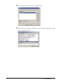
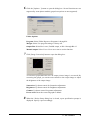
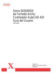
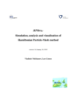
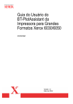
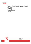
Xerox 6030/6050 Wide Format AutoCAD ADI/HDI Driver User Guide 701P41586 Version 1.3 May 2004 Xerox Corporation Global Knowledge & Language Services 800 Phillips Road Bldg. 845-17S Webster, NY 14580 Copyright © 2004 Xerox Corporation. All rights reserved. Printed in the United States of America. Copyright protection claimed includes all forms and matters of copyrighted material and information now allowed by statutory or judicial law or hereinafter granted, including without limitation, material generated from the software programs that are displayed on the screen such as styles, templates, icons, screen displays, looks, etc. Adobe® and the Adobe logo, InDesign®, Illustrator®, PageMaker®, Photoshop®, Acrobat®, Distiller®, and the Acrobat logo are either registered trademarks or trademarks of Adobe Systems Incorporated in the United States and/or other countries. The Creo wordmark, Creo logo, and the names of Creo products and services referred to this document are trademarks of Creo, Inc. Macintosh, Power Macintosh, and Mac are registered trademarks of Apple Computer, Inc. Microsoft® Windows NT® and Microsoft® Windows are trademarks of Microsoft Corporation. PANTONE® is a registered trademark of Pantone, Inc. Sun Microsystems and Solaris are a trademarks, registered trademarks, or service marks of Sun Microsystems, Inc. in the U.S. and other countries. SWOP® is a registered trademark of SWOP, Inc. Quark and QuarkXPress are trademarks of Quark, Inc. and all applicable affiliated companies, Reg. U.S. Pat. & Tm. Off. and in many other countries. Macromedia FreeHand® is a trademark of Macromedia, Inc. This product includes software developed by the Apache Software Foundation (http://www.apache.org). This product includes software developed by the JDOM Project (http://www.jdom.org). This product includes software developed by the Jaxen Project (http://www.jaxen.org). XEROX®, The Document Company®, the digital X®, Xerox 6030/6050 Wide Format AutoCAD ADI Driver are the trademarks of or licensed to XEROX CORPORATION. 2 Preface Thank you for using the 6030/6050 Wide Format AutoCAD ADI Driver (hereinafter known as Plotter Driver). This User Guide describes the procedures and precautions involved in installing and setting up Plotter Driver. Refer to the user manuals supplied with the Xerox 6030/6050 Wide Format Copier/Printer for details on relevant operations. The explanations provided in this User Guide assume that the user has a basic knowledge of operating the computer and network configuration in use. Refer to the manuals supplied with the computer, Windows related documentation and the manuals supplied with the network system for details on computer and network operations. Preface 3 Using This Guide Organization This guide consists of the following chapters. Chapter 1. Installing Plotter Driver Explains how to install Plotter Driver into your computer. 4 Using This Guide Conventions This User Guide uses the following symbols and conventions: < > key Indicates the keys on the keyboard. Press the <Enter> key. [ ] Indicates the menus and display items on the screens. Select either the [On] or [Off] buttons to display [Job Name], [Owner], and [Reason] in that order. " " Indicates areas of reference within this User Guide. Also indicates messages. Refer to "3.2 Print Services". A message stating "Additional Port Information Required. The Device could not be identified" appears. Indicates important information which you should read. Indicates additional information on operations or features. Indicates reference sources. Indicates examples. Using This Guide 5 6 Using This Guide Table of Contents Preface Using This Guide Table of Contents Chapter 1 Installing Plotter Driver 1.1 ADI Installation .......................................................................................................................... 2 Copy the Driver ...................................................................................................................... 2 Installing and Setting up the Driver ................................................................................... 2 1.2 HDI Installation .......................................................................................................................... 7 Copy the Driver ...................................................................................................................... 7 Installing and Setting up the Driver for Local Plotter ................................................... 7 .Installing and Setting up the Driver for Network Plotter............................................. 8 1.3 Driver Operation Reference ................................................................................................... 10 Change Driver Setup ........................................................................................................... 10 Check Driver Setup ............................................................................................................. 12 Index ....................................................................................................................................... 14 Table Of Contents Table Of Contents Chapter Chapter 0 1 Installing Plotter Driver Chapter 1 1.1 ADI Installation The following example is based on the assumption that AutoCAD is install in drive C: and the floppy drive is A:. AutoCAD is installed by the attached installer and has the standard directory configuration. Copy the Driver 1 Using Windows Explorer, go to the floppy disk and select the driver “plpxc_e.dll”. Then select [Copy] from the [Edit] menu. 2 Go to the AutoCAD R14/DRV subdirectory, and select [Paste] from the [Edit] menu. If AutoCAD is installed in a drive and directory that are different from the example, change the location accordingly. Installing and Setting up the Driver This section describes the procedures to install the driver into AutoCAD and make it available. 1 Start up AutoCAD R14 and select [Tools] and then [Preferences] to open the preferences dialog box. 2 Chapter 1 Installing Plotter Driver 2 Click the [Printer] tab to bring it to the foreground. 3 Click the [New...] button to display the “Add a Printer” dialog box. Then Select “Xerox DW series...”. The “Device Setup” dialog box opens. 1.1 ADI Installation 3 4 Optional functions unique to the printer model can be set by clicking [Options...] button. These settings can be changed later by selecting [Device and Default Selection] from the “Print/Plot Configuration” dialog box. 5 Setting items Select paper type: Select type of paper to be used from Bond, Film, or Vellum paper. Paper size: Select paper size. For this driver, paper size must be selected here, not at Paper Size and Orientation in the “Print/Plot Configuration” dialog box. Length: When “Custom size” is selected at “Paper Size”, its length can be set in integral value in 1mm increments. Set margin: Set a margin in the range of 0 to 10mm on each side of paper. This margin reduces the maximum plotting area. Fill: Set solid or halftone (dither) pattern for filling graphics or TrueType fonts Select resolution: Select resolution for raster (picture image) output. Image correction: Click here to open the sub-dialog for raster (picture image) gamma correction. Version: Version of this driver. Red print: Not supported by this model. Red-specified pen number: Not supported by this model. Number of Copies: Specify the number of copies (1 to 99). Select generated data: Select a plotter language (RTL/GL2/VCGL+MMR) to generate the data. ‘VCGL+MMR’ is not supported by some of the plotter models. Options: Click the ‘Options…’ button to open the sub-dialog to set optional functions unique to the selected plotter model. 4 Chapter 1 Installing Plotter Driver 6 Click the [Options...] button to open the dialog box. Several functions are not supported by some plotter models (grayed out options are not supported). Folder Options Program: Select Folder Bypass or Programs 1 through 20. Margin: Select Use program setting or Always off. Output Bin: Select Don’t care, Fanfold output, or Bin 1 through Bin 13. Manual output: Select Yes or No to use or not to use the function. 7 Click [Image Correction] button to open the dialog box. A correction graph indicates how an output picture image is corrected. By correcting the graph, you can increase contrast to the output image or adjust the brightness of the output image. Saturation: Up-down control for Saturation adjustment Brightness: Up-down control for Brightness adjustment Gamma: Up-down control for gamma adjustment Preset value: Reset the corrected graph to default 8 When the “Device Setup dialog box is closed, a port specification prompt is displayed. Specify a port accordingly. 1.1 ADI Installation 5 9 The current print settings are displayed. At the prompt “Do you want to change anything?”, enter N for No. Control returns to the “Preferences” dialog box. This completes the driver installation and setup. 6 Chapter 1 Installing Plotter Driver 1.2 HDI Installation The following example is to configure a local non-system plotter and network nonsystem plotter. Copy the Driver 1 Unzip the driver file. This will create subdirectories for 2000, 2000i, 2002 and 2004. Installing and Setting up the Driver for Local Plotter 1 Open the AutoDesk Plotter Manager. 2 In the AutoDesk Plotter Manager, double-click the Add-a-Plotter wizard. 3 In the Add-a-Plotter wizard, read the Introduction, and then choose Next to advance to the Add Plotter - Begin page. 4 On the Add Plotter - Begin page, choose My Computer. Choose Next. 5 Choose Have Disk to locate the HIF file on that driver disk, and install the driver supplied with your plotter. 6 On the Add Plotter - Plotter Model page, select a manufacturer and model. Choose Next. • (Optional) The Import PCP or PC2 screen enables you to use configuration information from a PCP or PC2 file created with an earlier version of AutoCAD. 7 On the Add Plotter - Ports page, select the port to use when plotting. Choose Next. The ports available for the specified device are displayed. 1.2 HDI Installation 7 8 On the Add Plotter - Plotter Name page, enter a name to identify the currently configured plotter. Choose Next. 9 When you reach the Add Plotter - Finish page, you can choose Finish to exit the Add-a-Plotter wizard. 10 A PC3 file for the newly configured plotter appears in the Plotters window, and the plotter is available for plotting in the list of devices. 11 At this time, you can change the default settings for the plotter by choosing Edit Plotter Configuration on the Add Plotter - Finish page. You can also perform a plot calibration test on your newly configured plotter by choosing Calibrate Plotter on the Add Plotter - Finish page. . Installing and Setting up the Driver for Network Plotter 1 Open the AutoDesk Plotter Manager. 2 Double-click the Add-a-Plotter wizard icon. 3 In the Add-a-Plotter wizard, read the Introduction, and then choose Next to advance to the Add Plotter - Begin page. 4 On the Add Plotter - Begin page, choose Network Plotter Server. Choose Next. 5 On the Add Plotter - Network Plotter page, enter the share name of the network plotter server that you want to use. • The server must already exist on the network. For more information, see your system administrator. • You must use the universal naming convention (UNC). The correct format of a UNC path is \\server name\share name. You can select an existing share name on your network by choosing Browse. 6 Choose Have Disk to locate the HIF file on that driver disk, and install the driver supplied with your plotter. 8 Chapter 1 Installing Plotter Driver 7 On the Add Plotter - Plotter Model page, select a manufacturer and model. Choose Next. • (Optional) The Import PCP or PC2 screen enables you to use configuration information from a PCP or PC2 file created with an earlier version of AutoCAD. 8 On the Add Plotter - Plotter Name page, enter a name to identify the currently configured plotter. Choose Next. 9 When you reach the Add Plotter - Finish page, you can choose Finish to exit the Add-a-Plotter wizard. 10 A PC3 file for the newly configured plotter appears in the Plotters window and the plotter is available for plotting in the list of devices. 11 At this time, you can change the default settings for the plotter by choosing Edit Plotter Configuration on the Add Plotter - Finish page. You can also perform a plot calibration test on your newly configured plotter by choosing Calibrate Plotter on the Add Plotter - Finish page. 1.2 HDI Installation 9 1.3 Driver Operation Reference The driver setup information set in the “Preferences” box at driver installation can also be changed when the PLOT command is executed. Change Driver Setup 1 Execute the PLOT command to open the “Print/Plot Configuration” dialog. 2 Click the “Device and Default Selection” button. 3 Select the 6030/6050 printer. 4 Click the “Change” button at “Device Requirements” in the opened dialog box. 5 The “Change Device Settings” dialog box opens. This is similar to the dialog box displayed at the driver installation. The driver setup information can be changed with this dialog box. This dialog box is almost the same as the “Device Setup” dialog box. Select paper type: Select type of paper to be used from “Bond”, “Film”, “Vellum” paper and “Use plotter setting”. 10 Chapter 1 Installing Plotter Driver Paper size: Select paper size. For this driver, paper size must be selected here, not at “Paper Size and Orientation” in the “Print/Plot Configuration” dialog box. Length: When “Custom size” is selected at “Paper Size”, set its length can be set in integral value in 1mm increments. Set margin: Set a margin in the range of 0 to 10mm on each side of paper. This margin reduces the maximum plotting area. Fill: Set a solid or halftone (dither) pattern for filling graphics or TrueType fonts. Select resolution: Select resolution for raster (picture image) output. Image correction: Click here to open the sub-dialog for raster (picture image) gamma correction. Versions...: Version of this driver Red print: Not supported by this model. Red-specified pen number: Not supported by this model. Label: Enter a message to add as a drawing label. Only alphanumeric characters (ASCII codes) can be used. The maximum number of characters is 64. Number of Copies: Specify the number of copies (1 to 99). Select generated data: Select a plotter language (RTL/GL2/VCGL+MMR) to generate the data. “VCGL+MMR” is not supported by some of the plotter models. Options...: Click the “Options...” button to open the dialog box to set optional functions unique to the selected plotter model. 6 Click the [Options...] button to open the dialog box. Several functions are not supported by some plotter models (grayed out options are not supported). Folder Options Program: Select Folder Bypass or Programs 1 through 20. 1.3 Driver Operation Reference 11 Margin: Select Use program setting or Always off. Output Bin: Select Don’t care, Fanfold output, or Bin 1 through Bin 13. Manual output: Select Yes or No to use or not to use the function. 7 Click [Image Correction] button to open the dialog box. A correction graph indicates how an output picture image is corrected. By correcting the graph, you can increase contrast to the output image or adjust the brightness of the output image. Saturation: Up-down control for Saturation adjustment Brightness: Up-down control for Brightness adjustment Gamma: Up-down control for gamma adjustment Preset value: Reset the corrected graph to default Check Driver Setup The current driver setup information can be displayed in the following procedures: 1 Execute the PLOT command to open the “Print/Plot Configuration” dialog. 2 Click the “Device and Default Selection...” button. 3 Select the 6030/6050 printer. 4 Click the “Show” button at “Device Requirements” in the opened dialog box. 5 The “Show Device Requirements” message box opens. This message box displays the current driver setup information. 12 Chapter 1 Installing Plotter Driver 1.3 Driver Operation Reference 13 Index I Installing Plot Driver (Windows XP) ................... 2, 14 Index 7