1
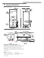
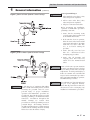
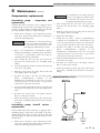
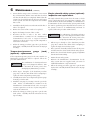
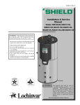
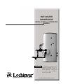
HOT WATER GENERATOR INSTALLATION and OPERATION MANUAL Unit shown with optional control package. WARNING The information contained in this manual is intended for use by qualified professional installers, or service technicians. Consult your local expert for proper installation or service procedures. Save this manual for future reference. Hot Water Generator Installation and Operation Manual Contents Contents . . . . . . . . . . . . . . . . . . . . . . . . . . . . . . . . . . . . . . . . . . . . . . . . . . . . . . . 2 Hazard definitions . . . . . . . . . . . . . . . . . . . . . . . . . . . . . . . . . . . . . . . . . . . . . . . . 2 1. General information . . . . . . . . . . . . . . . . . . . . . . . . . . . . . . . . . . . . . . . . . . . . 3 Availability . . . . . . . . . . . . . . . . . . . . . . . . . . . . . . . . . . . . . . . . . . . . . . . . . . 3 Optional control packages . . . . . . . . . . . . . . . . . . . . . . . . . . . . . . . . . . . . . . 4 2. Installation . . . . . . . . . . . . . . . . . . . . . . . . . . . . . . . . . . . . . . . . . . . . . . . . . . . 6 3. Operation . . . . . . . . . . . . . . . . . . . . . . . . . . . . . . . . . . . . . . . . . . . . . . . . . . . . 10 Startup procedure . . . . . . . . . . . . . . . . . . . . . . . . . . . . . . . . . . . . . . . . . . . . . 10 Shutdown procedure . . . . . . . . . . . . . . . . . . . . . . . . . . . . . . . . . . . . . . . . . . . 10 4. Inspection . . . . . . . . . . . . . . . . . . . . . . . . . . . . . . . . . . . . . . . . . . . . . . . . . . . . 11 5. Troubleshooting . . . . . . . . . . . . . . . . . . . . . . . . . . . . . . . . . . . . . . . . . . . . . . . 12 6. Maintenance . . . . . . . . . . . . . . . . . . . . . . . . . . . . . . . . . . . . . . . . . . . . . . . . . . 15 Storage tank maintenance . . . . . . . . . . . . . . . . . . . . . . . . . . . . . . . . . . . . . . 15 Component(s) replacement . . . . . . . . . . . . . . . . . . . . . . . . . . . . . . . . . . . . . . 17 7. Notes page . . . . . . . . . . . . . . . . . . . . . . . . . . . . . . . . . . . . . . . . . . . . . . . . . . . 22 Hazard definitions The following defined terms are used throughout this manual to bring attention to the presence of hazards of various risk levels or to important information concerning the life of the product. DANGER DANGER indicates an imminently hazardous situation which, if not avoided, will result in death or serious injury. WARNING WARNING indicates a potentially hazardous situation which, if not avoided, could result in death or serious injury. CAUTION indicates a potentially hazardous situation which, if not avoided, may result in minor or CAUTION moderate injury. CAUTION NOTICE 2 CAUTION used without the safety alert symbol indicates a potentially hazardous situation which, if not avoided, may result in property damage. NOTICE indicates special instructions on installation, operation, or maintenance that are important but not related to personal injury or property damage. Hot Water Generator Installation Instructions 1 General information WARNING • Before using product, read and understand instructions. • Save these instructions for future reference. • All work must be performed by qualified personnel trained in the proper application, installation, and maintenance of steam systems and/or boiler water systems in accordance with all applicable codes and ordinances. • To prevent serious burns, wear heat resistant gloves when opening and closing steam valves, or handling hot equipment. • To prevent serious burns, the internal pressure of the trap must be 0 psi (0 bar) before servicing. • To prevent serious personal injury from steam pipe blow down, connect a temporary pipe between the steam pipe opening and a drain, or stand at least 100 ft. (30 m) from the front of the pipe opening. • To prevent property damage, personal injury, or death, cap off the gate valves if they are not connected to a drain and when they are not in use for test or pressure relief. Failure to follow this warning could cause property damage, personal injury, or death. This manual is intended to cover installation, operation, and maintenance procedures for Lochinvar’s Hot Water Generator Systems. Since each unit is built to meet customer specifications, instructions may not be specific to every system. If questions are not answered by this manual, or if specific installation, operation, and/or maintenance procedures are not clearly understood, contact Lochinvar for clarification before proceeding. These Hot Water Generator Systems are designed for indoor use only, unless otherwise required by design specifications. Each unit requires at least two feet of clearance around and above the unit. It should be located on a level surface (no more than one-half degree of slope), capable of supporting the total weight of the unit when filled to capacity. The unit should be mounted to the floor following applicable architectural and local code requirements for the specific installation site. Note: Tanks do not come standard with floor tie downs. The high quality enamel paint, applied to the jacket of the unit, will provide years of protection against corrosion. If it is necessary to clean the outside of the unit, a mild cleaning agent should be used that will not damage the paint. For all piping connections, the use and/or type of joint compound or sealer on the joints should be determined by referring to local codes, accepted standards, and/or the requirements of the installing contractor. Lochinvar’s Hot Water Generator Systems are ideal when boiler capacity is sufficiently sized to cover potable hot water demand and provide source water for hydronic heating systems. Hot Water Generator Systems use steam or boiler water as an energy source and can provide high recovery rates, making them an economical water heating system for end users. Availability Hot Water Generator Systems are pre-engineering and preassembled complete with all piping to meet your specific application. And like every Lochinvar product, we thoroughly test them to ensure proper performance from the moment they are installed. Hot Water Generator Systems are available in horizontal or vertical configurations (see FIG.’s 1 and 2) in a wide array of gallon capacities. Standard packages are available in tank sizes from 200 - 1000 gallons with single wall copper tube bundle heating units. Custom configurations, smaller and larger tank and tube bundles, and optional control packages are also available. Consult the factory for specifications. Tank Construction -- Lochinvar tanks are available with glass or cement lining. ASME -- All Lochinvar tanks are constructed in accordance with ASME standards and certified for 125 psi working pressure (standard) or 150 psi working pressure (optional). Cathodic Protection -- All glass lined tanks are equipped with magnesium anodes to provide protection against corrosion. Manway - A manway is provided as an option on glass lined tanks and is standard on cement lined tanks. *Horizontal tanks with tube bundles 48" and longer require a manway. Tank Circulator Package -- All standard Hot Water Generator Systems are equipped with a circulator package to maximize the amount of hot water provided. Five-Year Limited Tank Warranty -- Provides warranty protection against tank failure (see warranty for details). One-Year Limited Warranty -- Tube Bundle, parts, accessories and controls (see warranty for details). 3 Hot Water Generator Installation and Operation Manual 1 General information Figure 1_Vertical Tanks Figure 2_Horizontal Tanks Optional control packages (see page 5) Steam to Water -- Control packages include an isolation valve, 2-way self-operated temperature regulator, inlet and outlet wye strainers, a float and thermostatic steam trap and all necessary piping. Water to Water -- Control packages include isolation valves, 2-way self-operated temperature regulator, inlet wye strainer and all necessary piping. Options: • Manual Reset High Limit • Solenoid Valve • Manway (see notes on manway) • 150 psi Tank Working Pressure • Temperature & Pressure Gauge • Vacuum Breaker 4 Hot Water Generator Installation and Operation Manual 1 General information (continued) Figure 3_Steam to Water Optional Control Package WARNING Areas of potential danger: 1. All steam/boiler water lines, joints, valves, and pressure regulators. 2. All hot water outlet lines, joints, valves, and pressure regulators. 3. All power connections and cables. Before attempting any installation, operation, or maintenance procedures pertaining to this unit: 1. Assure that the incoming steam (or boiler water) has been turned off at the manual shutoff valve. 2. If the unit has been in operation, allow the water in the heater and all components and surfaces (incoming steam line, hot water outlet line, etc.,) to cool before starting the procedure. 3. Assure that all power has been shut off / disconnected before attempting any procedures. Figure 4_Water to Water Optional Control Package 4. Assure that all incoming and outgoing water lines have been turned off at the manual shutoff valves. WARNING Steam or boiler water present situations that can be very dangerous due to the fact they are under pressure and at very high temperatures. To avoid possible injury or death, use common sense and follow all accepted and recommended procedures when performing installation, operation, and maintenance procedures. WARNING WARNING As with any piece of equipment that utilizes steam or boiler water under pressure, as well as electricity, the potential exists for severe personal injury if proper installation, operation, and maintenance procedures are not followed. Listed in this section are specific warnings pertaining to Lochinvar Hot Water Generators. In addition, throughout this manual, warnings are restated when procedures are described pertaining to areas of potential danger. All warnings should be carefully read and understood. All precautions contained in the warnings should be carefully followed to reduce the chance of injury. The combination of electricity and water can pose a very dangerous situation. Assure that all power has been shut off / disconnected before attempting any installation or maintenance procedures. 5 Hot Water Generator Installation and Operation Manual 2 Installation Transporting and unpacking the unit Each Lochinvar Hot Water Generator is crated as necessary at the factory. The crating is designed to provide protection for the unit during transportation, and to provide a safe means by which to lift and move the unit with a fork lift or hand truck. In order to prevent damage during shipment the controls package is disassembled at the factory after leak testing. Reassembly will require re-attaching the unions (or bolting flange) to the appropriate locations and insertion of the control valve bulb into the provided bulbwell and the system is ready for operation (see FIG.’s 5 and 6 below). All hardware for the reassembly is included with the system. Drawings of the specific controls package are included with each product illustrating the finished assembly. For water to water systems the bypass piping union may remain attached for shipment. See FIG.’s 5 and 6 below for a detailed explanation of the break points. Figure 5_Steam to Water Storage Heater Figure 6_Water to Water Storage Heater 6 Hot Water Generator Installation and Operation Manual 2 Installation (continued) Examining the unit After the unit has been set in place and uncrated, it should be carefully examined to assure that neither the main unit nor components have been damaged during shipping. If any evidence of damage is detected that could affect the safe operation of the unit, contact Lochinvar Corporation, or your authorized sales representative, to report the damage and to receive instructions on how to proceed. After the unit and all components have been inspected for damage, it is suggested that all pressure and temperature control components be checked to assure that they meet or exceed design specifications. If any discrepancy is found, contact Lochinvar Corporation, or your authorized representative, before proceeding with the installation. Mounting the unit The unit should be mounted to the floor, following applicable architectural / local code requirements, or accepted standards for the specific installation site. The unit should be installed in a location with sufficient clearance to remove the tube bundle for repair or replacement. Unit and components Lochinvar Hot Water Generators are designed to make installation a relatively simple procedure. Because the unit is “Packaged”, after placing and mounting the unit, installation involves the following: • Connecting the cold water source to the water inlet. • Connecting the hot water outlet to the hot water feed line. • Installing the control valve bulb into the tank bulbwell. • Connecting the condensate / water return line and piping it to the recycling system. • Piping the pressure relief valve to an acceptable drain. • Connecting the energy source (steam or boiler water) to the unit. • Wiring the applicable source of electricity (if the unit is packaged with a circulating pump or electrically activated pressure or temperature controls). Connecting the cold water source and the hot water outlet NOTICE Before making any connections of water inlet or outlet to the unit, assure that all piping is clean and free of foreign material or scale. This can usually be accomplished by “blowing out” the pipe. Any foreign material or scale entering the unit can adversely affect operation and performance. Cold water source The first step in the installation process is to connect the cold water source to the water inlet port. The exact location of this port for the specific unit, as well as inlet pipe diameter and thread size, can be determined from the CAD drawing supplied with the unit. A manual shutoff valve should be installed upstream on the cold water source as an isolation device. The shutoff valve should be in the closed position and remain so until the installation is complete. NOTICE For all piping connections, the use and / or type of joint compound or sealer on the joint should be determined by referring to local codes, accepted practices, or the requirements of the installing contractor. If the cold water source is equipped with an in-line check valve or backflow preventer, a suitable expansion tank must be installed in the hot water outlet side of the system. See the supplied CAD drawing(s) or contact Lochinvar Corporation for expansion tank specifications. Hot water outlet The next step in the installation process is to connect the hot water system piping to the hot water outlet port. The exact location of this port for the specific unit, as well as outlet pipe diameter and thread size, can be determined from the CAD drawing(s) supplied with the unit. A manual shutoff valve should be installed downstream on the hot water outlet line as an isolation device in case the unit must be disconnected from the system. The shutoff valve should be in the closed position and remain so until the installation is complete. Each unit is supplied with CAD drawings that indicate the location and specifications for each connection that must be made. In addition, the drawing will enable the installer(s) to determine the flow direction of both the water and energy source. 7 Hot Water Generator Installation and Operation Manual 2 Installation Connecting the energy source (Steam or boiler water) WARNING Steam or boiler water present situations that can be very dangerous because of the high temperatures and pressures. Use common sense and follow all accepted and recommended procedures when performing installation, operation, and maintenance procedures to avoid possible injury or death. Assure that a manual shutoff valve is installed upstream in the steam or boiler water line (energy source), and that it is functioning properly. If any doubt exists concerning the integrity of the shutoff valve, replace the valve before attempting installation. All energy source valves should be closed and remain closed throughout the installation process. Connect the energy source to the line(s) leading to the temperature control valve. The exact location of the temperature control valve for the specific unit, as well as energy source pipe diameter and thread size, can be determined from the CAD drawing(s) supplied with the unit. NOTICE For all energy source piping connections, the use and / or type of joint compound or sealer on the joint should be determined by referring to local codes, accepted practices, or the requirements of the installing contractor. Connecting the steam condensate line or the boiler water return lines Steam condensate return line As the heat is extracted from the steam and transferred to the water heating system, condensate will form. This condensate must have a means by which it can drain from the unit and return to the steam system. The condensate return line serves this purpose. The condensate return line should be connected to the unit at the condensate return port. The condensate port is normally located downstream from the main and auxiliary traps. The exact location of this port for the specific unit, as well as the condensate return pipe diameter and thread size, can be determined from the CAD drawing(s) supplied with the unit. The condensate line should be piped back into the site’s steam system for recycling. A manual shutoff valve should be installed downstream in the condensate return line to allow the unit to be isolated from the system. The condensate shutoff valve will prevent backflow of steam if the line is disconnected. 8 WARNING Do not attempt to lift condensate with a float and thermostatic trap. Pipe the condensate outlet from the main steam trap to a gravity drain or to a condensate pump. Lifting condensate without the assistance of a condensate pump can cause erratic temperature control, failure of the tube bundle, damage to the control valve, or damage to the condensate trap. Any failure caused due to lifting of condensate without a condensate pump is not covered by the warranty. Boiler water and high temperature water return line After the boiler water has passed through the tube bundle, and the heat has been extracted and transferred to the domestic water system, the water must return to the system. The water return line serves this purpose. The water return line should be connected to the unit at the return port. Unlike the steam condensate return line, the return lines for boiler water do not have in-line condensate traps. The exact location of this port for the specific unit, as well as the water return pipe diameter and thread size, can be determined from the CAD drawing supplied with the unit. A manual shutoff valve should be installed downstream in the water return line to allow the unit to be isolated from the system. The water return shutoff valve will present backflow of boiler water if the line is disconnected. Piping the relief valves to drain All Lochinvar Hot Water Generators are equipped with a pressure relief valve for the tank. The valve should be piped to a vent line leading to a suitable drain. Piping the pressure relief valves to suitable drains will prevent both water and heat damage to the unit, as well as reduce the risk of injury from released steam or water. The pipe must be of adequate size to properly handle the capacity of the relief valve and vent line. Check local codes to assure compliance. If a check valve has been installed on the inlet water line, thermal expansion may take place causing build up of excessive pressure when the water is being heated. This expansion will cause the relief valve to open, releasing hot water to the vent line. Hot Water Generator Installation and Operation Manual 2 Installation WARNING (continued) Do not install a valve between the water heater relief valve and the vent. Doing so could cause serious injury or death if the pressure relief valve released and the manual valve was closed. This would cause excessive buildup of pressure in the water heater which could result in an explosion. Completing installation Installation of the Lochinvar Hot Water Generator is now complete. All documentation supplied with the unit should be passed along to maintenance personnel for future reference. Connecting the circulation pump and electrically activated controls Lochinvar Hot Water Generators are equipped with a circulation pump. If the unit being installed is so equipped, the correct power source(s) must be connected. The circulation pump must run all the time. Wire this pump to a correctly sized disconnect switch per local codes. WARNING The combination of electricity and water can pose a very dangerous situation. Assure that all electric power has been turned off before attempting any installation or maintenance procedures. Reference the wiring CAD drawing included with the unit, or the installation instructions contained in the Installation Manual for the component, for specific wiring instructions. NOTICE All power connections should be performed by trained, certified electricians. 9 Hot Water Generator Installation and Operation Manual 3 Operation After all installation procedures have been completed, and all water, energy source joints, and power connections have been double checked, the unit is ready for operation. As a precaution, it is strongly suggested that the following Startup and Shutdown procedures be followed. WARNING Steam or boiler water present situations that can be very dangerous because of the high temperatures and pressures. Use common sense and follow all accepted and recommended procedures when performing installation, operation, and maintenance procedures to avoid possible injury or death. Startup procedure 1. 2. Assure that all manual shutoff valves on the water and energy source lines are closed. Slowly open the manual shutoff valve on the cold water inlet line, checking to assure that there are no leaks at the valve or any joints. Allow the tank to fill with water. As the tank is filling, hold the pressure relief valve open to allow air to bleed out of the tank. This will speed the filling process. 3. Adjust the operating temperature control to the desired operating temperature. 4. Set the high temperature limit thermostat at 10 to 15 degrees Fahrenheit (10°F to 15°F) above the desired operating temperature. 5. If the unit is so equipped, turn on the internal circulating pump. The circulating pump will operate constantly as long as power is supplied to the pump. Shutoff valves are located on the inlet and/or outlet side of the circulating pump line. These valves should be opened before the pump is turned on. After the power to the pump is turned on verify that the pump is working. If the pump is an oil lubricated unit, verify proper oiling. 6. Open the valve on the condensate drain line, or boiler water return line. 7. For steam to water controls, slowly open the manual shutoff valve on the steam inlet. Create a load/demand situation of approximately 10 to 25% of the system design conditions. As the valves are being opened, check for leaks at the valves and all pipe joints. 8. For water to water controls, slowly open the manual shutoff valves on the boiler water inlet and outlet lines. Create a load/demand situation of approximately 10 to 25% of the system design conditions. As the valves are being opened, check for leaks at the valves and all pipe joints. Open the bypass loop ball valve approximately half way. Allow the system to push air out of the tube bundle and the piping slowly. Note: It should be noted that when the control valve is closed the boiler water will flow through the bypass loop. When the valve is open, less water will “bypass”. Adjustment of the bypass loop ball valve will be necessary to balance your system. For initial installation the bypass valve should be closed. 10 9. Turn on power to the rest of the electrically controlled components of the unit (if equipped). 10. As the unit is initially heating the water, carefully re-inspect cold water inlet, hot water outlet, steam inlet (or boiler water inlet), and condensate return (or boiler water return line) joints for signs of leakage. 11. As the unit approaches the desired operating temperature, adjust the temperature control valve. 12. After the unit has reached operating temperature, reinspect all joints for signs of leakage. In addition, check all gauges and controls to verify that the water temperature and pressure, as well as energy source pressure, are within design specifications. 13. The unit is now ready for normal operation. Shutdown procedure 1. Turn off all power to the circulating pump and/or electric controls, if equipped. 2. Close all valves in the steam inlet line (or boiler water line). 3. Relieve the pressure from the energy source line (steam or boiler water), where possible. 4. Close all remaining valves in the system in this order: • the hot water outlet line; • the cold water inlet line; and • the condensate return line (or boiler water return line) 5. After the system has cooled, drain the unit by opening the tank drain valve and holding the pressure relief valve in the open position. This will prevent the formation of a vacuum and increase the drainage flow. 6. Proceed with the required maintenance or repairs. 7. After performing the required maintenance or repairs, return the unit to operation by following the Startup Procedure. Hot Water Generator Installation and Operation Manual 4 Inspection The following table summarizes the recommended time intervals for inspections of the water heater, components, inlet and outlet water, energy source lines (steam or boiler water), and power connections. RECOMMENDED INSPECTIONS Time Interval To Be Inspected Per Manufacturer Specs Circulating Pump Control Valves Temperature & Pressure Weekly Monthly Quarterly Gauges - Pressure & Temperature Lines - Inlet, Outlet, & Return Power Connections Pressure Relief Valve Shutoff Valves - Manual Annually Single Solenoid Safety System Strainers Temperatures - Water & Operating Thermometer SemiQuarterly Traps - Main & Auxiliary Magnesium Anode Rods 11 Hot Water Generator Installation and Operation Manual 5 Troubleshooting SYMPTOM PROBABLE CAUSE Water heater does not • The thermometer is not sensing the water temperature. maintain the required temperature at the rated capacity. CORRECTIVE ACTION correctly • Check the water temperature with a temperature gauge that is known to be correct. Replace the thermometer if it is found to be incorrectly sensing the water temperature. • Inlet energy source pressure is too • Check the primary energy source pressure/temperature. If the reading is low or boiler water temperature is too low. low, adjust the inlet pressure/temperature to meet the design requirements. If there is a restriction in the primary energy source line, the pressure reading will drop excessively when the generator calls for full energy on steam systems, even though the pressure seems to be normal during light demand. If the primary pressure is correct, the system should reach design pressure for energy source in the tube bundle as the temperature of the water in the tank heater approaches shutoff. • The condensate / water return piping has not been installed properly, allowing the condensate / water to drain freely (by gravity); the condensate / water drain line is restricted; or the condensate / water check valve is leaking or has failed. • Water bypass valve adjusted (boiler water). has not • Reconfigure the condensate / water return piping and check valve to allow for proper drainage. Check to assure that there is no restriction in the condensate / water drain line. Replace the check valve if it is leaking or has failed. Also, check to assure that there is no restriction in the condensate / water drain line. been • Adjust bypass valve approximately half closed. Readjust as necessary. • Control valve bulb not installed or not • Notify factory for replacement. properly installed in tank bulbwell. • Control valve actuator defective. • Verify actuator is not working. Notify factory for replacement. correctly • Check the water temperature with a temperature gauge that is known to be correct. Replace the thermometer if it is found to be incorrectly sensing the water temperature. • The condensate / water return piping • Reconfigure the condensate / water has not been installed properly, return piping and check valve to allow allowing the condensate / water to for proper drainage. Check to assure drain freely (by gravity); the that there is no restriction in the condensate / water drain line is condensate / water drain line. Replace restricted; or the condensate / water the check valve if it is leaking or has check valve is leaking or has failed. failed. Also, check to assure that there is no restriction in the condensate / water drain line. Outlet temperature is too • The thermometer is not sensing the water temperature. high. • Control valve bulb not installed or not • Verify bulb is installed in bulbwell. properly installed in tank bulbwell. • Control valve actuator defective. 12 • Verify actuator is not working. Notify factory for replacement. Hot Water Generator Installation and Operation Manual 5 Troubleshooting SYMPTOM (continued) PROBABLE CAUSE CORRECTIVE ACTION Outlet temperature • Inlet energy source pressure is too • For steam systems check the primary low or boiler water temperature is too low. energy source pressure/temperature. If the fluctuates widely. reading is low, adjust the inlet pressure/temperature to meet the design requirements. If there is a restriction in the primary energy source line, the pressure reading will drop excessively when the generator calls for full energy on steam systems, even though the pressure seems to be normal during light demand. If the primary pressure is correct, the system should reach design pressure for energy source in the tube bundle as the temperature of the water in the tank heater approaches shutoff. • The condensate / water return piping • Reconfigure the condensate / water return piping and check valve to allow has not been installed properly, for proper drainage. Check to assure allowing the condensate / water to that there is no restriction in the drain freely (by gravity); the condensate / water drain line. Replace condensate / water drain line is the check valve if it is leaking or has restricted; or the condensate / water failed. Also, check to assure that there check valve is leaking or has failed. is no restriction in the condensate / water drain line. • The primary / inlet temperature control • Verify control valve bulb was installed in the bulbwell. valve is not closing properly. • Bypass water). valve not adjusted (boiler • Adjust bypass valve approximately half closed. Readjust as necessary. • The primary / inlet temperature control • Verify control valve actuator is working properly , if not replace. valve is not opening properly. Excess or insufficient • The condensate / water return piping • Reconfigure the condensate / water has not been installed properly, return piping and check valve to allow condensate (boiler water) allowing the condensate / water to for proper drainage. Check to assure being returned from the drain freely (by gravity); the that there is no restriction in the unit. condensate / water drain line is restricted; or the condensate / water check valve is leaking or has failed. condensate / water drain line. Replace the check valve if it is leaking or has failed. Also, check to assure that there is no restriction in the condensate / water drain line. • Bypass loop valve not adjusted (boiler • Adjust bypass valve approximately half closed. Readjust as necesssary. water). Steam being discharged • The tube bundle is heavily scaled or • Call Lochinvar Corporation, or an into the condensate damaged. authorized sales agent for instructions on repair or replacement. drain. 13 Hot Water Generator Installation and Operation Manual 5 Troubleshooting SYMPTOM Pressure “pops”. relief PROBABLE CAUSE CORRECTIVE ACTION valve • The primary / inlet temperature control • Verify control valve bulb was installed in valve is not closing properly. tank bulbwell. control valve • The secondary / outlet energy source • Verify pressure control system is not operating properly. operating properly. actuator is • The over-temperature limit system is • Check the individual components of the out of adjustment, or some component system and repair or replace the failed of the system has failed. component(s) as necessary. Water shuts down at or • The over-temperature limit system is • Check the individual components of the system and repair or replace the failed too close to (above or out of adjustment, or some component of the system has failed. component(s) as necessary. below) the design outlet temperature. A loud banging in the • The condensate / water return piping • Reconfigure the condensate / water water heater, primary has not been installed properly, return piping and check valve to allow allowing the condensate / water to for proper drainage. Check to assure piping, or condensate / drain freely (by gravity); the that there is no restriction in the water return piping (not condensate / water drain line is condensate / water drain line. Replace to be confused with a restricted; or the condensate / water the check valve if it is leaking or has normal clicking noise check valve is leaking or has failed. failed. Also, check to assure that there made during operation). is no restriction in the condensate / water drain line. • Primary / inlet steam line is not • The steam supply should be clean dry properly trapped (steam as energy steam. Do not slug controls system source only). with boiler startup condensate. This can damage controls as well as tube bundle. 14 Hot Water Generator Installation and Operation Manual 6 Maintenance Storage tank maintenance A new tank installation should have a regular inspection program set up. The first inspection should be within the first three months of operation. Once the tendency to accumulate sediment has been established, the inspection program can be modified to suit the water conditions. Typical inspection programs flush the tank at six-month intervals and clean the tank in yearly intervals. Deliming solvents or acid type flush agents are not recommended for use in lined storage tanks. These chemical cleaners are usually designed for use in non-potable systems such as heating boilers. These chemicals may be aggressive and cause damage to the tank lining and deteriorate the magnesium anodes supplied in glass-lined storage tanks. WARNING Hot water will be released under pressure. Avoid contact with the hot discharge water to prevent the risk of severe scald injury. 9. Turn on electric power to the circulating pump and other electrical components if necessary. 10. Observe tank and piping to ensure all components are functioning properly. Cleaning the storage tank The mineral accumulation in an un-fired tank will be in a soft sediment form that can be removed by a regular cleaning of the lower portion of the tank. Many tanks will have a hand hole or a larger manway to allow access to the interior of the tank for complete removal of accumulated sediment. An access opening to remove the manway or hand hole is provided in the exterior jacket. The sheetmetal jacket components are removed with hand tools. The opening will be in the bottom portion of a vertical tank and on the end of a horizontal tank (see FIG’s 1 and 2 on page 4 of this manual). To clean the tank, follow these steps (reference FIG.’s 7 and 8): 1. Close valves from boiler water or steam supply and return or condensate pipes. Since the mineral accumulation is occurring in an un-fired tank it will be in a soft sediment form. This soft sediment can be removed by a regular flushing of the lower portion of the tank. 2. Turn off electrical power to the circulating pump and other electrical components if necessary. 3. Close the valve on the hot water outlet on the top of the storage tank and the cold water supply to the system. To flush the tank, follow these steps: 4. Ensure that the drain located on the bottom of the tank is routed to a floor drain with adequate capacity to allow the tank to be drained. 5. Open the drain valve and open a vent to allow the air to enter the tank (manually opening the relief valve will usually accomplish this). Use extreme caution, as the water exiting the tank drain may be very hot. Avoid contact with the hot discharge water to prevent the risk of severe scald injury. 6. Allow the tank to drain completely. 7. Remove the jacket cover over the manway or hand hole. Remove the bolt(s) securing the tank access opening. Use a flashlight to observe the sediment collected in the tank. 8. Use hand tools to remove all sediment from the interior of the tank. Use care not to damage the interior lining of the storage tank. 9. Use a water hose to flush the remaining sediment from the interior surfaces of the tank and ensure that all debris is removed. Scale or sediment allowed to reach the potable system can foul valves, pumps, strainers, and other water fixtures. Ensure that the tank interior is clean before refilling the vessel. Flushing the storage tank 1. Turn off electrical power to the circulating pump and any other tank accessories. 2. Close the valve on the hot water outlet on the top of the storage tank. 3. Ensure that the drain located on the bottom of the tank is routed to a floor drain with adequate capacity to allow the tank to be flushed. 4. Open the drain valve and allow the incoming cold water to flush the soft sediment out the bottom of the storage tank. Use extreme caution, as the water exiting the tank drain may be very hot. Avoid contact with the hot discharge water to prevent the risk of severe scald injury. 5. Observe the color of the water initially discharged from the tank drain. This water will generally be milky or slightly discolored by the sediment discharge. Allow the drain to run until the water runs clear. 6. Close the drain valve on the tank. 7. Open the hot water outlet valve on the top of the tank. 8. Open an adjacent hot water tap to purge any air that may have entered the storage tank during the draining process. Close the hot water tap if no air discharge is observed. 15 Hot Water Generator Installation and Operation Manual 6 Maintenance 10. Install a new gasket on the manway or hand hole to prevent any possible leaks. Tighten the gasket properly to prevent leaks. Caution: Over tightening can result in cutting the gasket and allowing a water leak to occur. 11. Replace the jacket cover over the manway or hand hole. 12. Close the drain and open the cold water supply and hot water outlet. If the relief valve was used for a vent ensure that it is now closed. Open the closest hot water valve to allow the air in the tank to vent as water enters the vessel. Close the valve opened for a vent when water flows from the valve. 13. Check the manway or hand hole and all related piping for any water leaks. 14. Turn on electric power to the circulating pump and other electric components if necessary. 15. Open valves for boiler water or steam supply. Also open the boiler water return, or condensate line. 16. Observe tank and piping to ensure all components are functioning properly. Figure 7_Horizontal Storage Tank w/Anodes 16 Magnesium anode rod inspection Glass lined storage tanks have a magnesium anode(s) to provide cathodical protection of the lining and minimize corrosion. Aggressive water conditions in some areas of the country may accelerate the deterioration of the anode(s). The anode(s) should be periodically removed and inspected to determine if replacement is necessary. The tank must be valved off from the system and fully drained to remove an anode for inspection. Anodes are supplied in threaded fittings on the top head of small vertical storage tanks. Top mounted anodes may be accessed by removing the jacket top. Large vertical storage tanks and horizontal storage tanks have multiple anodes installed in threaded tappings along the length of the tank. These anodes may be accessed by removing a jacket panel and/or corner post corresponding to the mounting point of the anodes. Adequate service clearance is required to allow removal of an anode. The anode(s) should be replaced when more than six inches of the core wire is exposed at either end of the rod. Medium sized tanks with round jackets provide an opening for individual anode rod access. Figure 8_Vertical Storage Tank w/Anodes Hot Water Generator Installation and Operation Manual 6 Maintenance (continued) Component(s) replacement Circulating pump replacement - inspection WARNING and Lochinvar Hot Water Generators can be equipped with a circulating pump to assist in the even heating of the water. If the unit is equipped with a circulating pump, the following procedure should be followed to replace the pump. 1. Follow Steps 1 through 5 of the shutdown procedure (page 10) to take the unit off-line before attempting to service the circulating pump. WARNING The combination of electricity and water can pose a very dangerous situation. Turn off / disconnect all electric power before attempting any maintenance procedure. 2. Refer to the manufacturer’s documentation supplied with the unit pertaining to testing the pump. If found to be defective or questionable, replace the pump by continuing with the steps that follow. 3. After assuring that the power has been turned off, disconnect the electric leads to the circulating pump (FIG. 9). The combination of electricity and water can pose a very dangerous situation. Turn off / disconnect all electric power before attempting any maintenance procedure. 2. After assuring that the power has been turned off, disconnect the electric leads to the circulating pump (FIG. 9). 3. Break the joints between the pump and the inlet and outlet piping. Remove the pump. 4. Remove the shutoff valves. 5. Install the new valves. Follow recommendations contained in the manufacturer’s documentation, local codes, or accepted contractor practices as to the use and / or type of joint compound or sealer at the connections. 6. Reconnect the pump to the inlet and outlet piping. Follow recommendations contained in the manufacturer’s documentation, local codes, or accepted contractor practices as to the use and / or type of joint compound or sealer at the connections. 7. Open the manual shutoff valves located on the inlet and outlet sides of the pump. 8. Reconnect the electric leads to the pump (reference FIG. 9 to assure proper wiring). 9. Follow the startup procedures (page 10) to put the unit back on-line. Carefully check all joints for any sign of leakage. 4. Close the manual shutoff valves located near the inlet and outlet ports of the pump. 5. Break the joints between the pump and the inlet and outlet piping. Remove the pump. 6. Reconnect the pump to the inlet and outlet piping. Follow recommendations contained in the Figure 9_Pump Wiring Diagram manufacturer’s documentation, local codes, or accepted contractor practices as to the use and / or type of joint compound or sealer at the connections. 7. Open the manual shutoff valves located on the inlet and outlet sides of the pump and check for any leakage at the joints. 8. Reconnect the electric leads to the pump (reference FIG. 9 to assure proper wiring). 9. Follow the startup procedures (page 10) to put the unit back on-line. Carefully check all connections for any sign of leakage. Circulating pump replacement shutoff valves - If the Lochinvar Hot Water Generator is equipped with a circulating pump to assist in the even heating of the water, manual shutoff valves will be located on both the inlet and outlet side piping. To replace the valves, follow the procedure detailed below. 1. Follow Steps 1 through 5 of the shutdown procedure (page 10) to take the unit off-line before attempting to service the circulating pump shutoff valves. 17 Hot Water Generator Installation and Operation Manual 6 Maintenance 3. Power connections - rewiring If any of the power connections must be rewired at the circulating pump or electrically activated controls, follow the steps listed below. WARNING Follow Steps 1 through 4 of the shutdown procedure (page 10) to take the unit off-line before attempting any electrical service. 2. After assuring the power has been turned off, disconnect and rewire the electrical connections in question. 3. Turn the power on and check that the component that has been rewired is functioning properly. 4. Slowly open the shutoff valves on the condensate (or boiler water return) line, cold water inlet line, and hot water outlet line. 5. Slowly open the shutoff valves on the energy source inlet line. Tube bundle replacement - inspection and The tube bundle is the heart of the Lochinvar Hot Water Generator. It should be removed and inspected every two (2) years. WARNING Steam or boiler water present situations that can be very dangerous because of the high temperature and pressures. To avoid possible injury or death, use common sense and follow all accepted and recommended procedures when performing installation, operation, and maintenance procedures. The combination of electricity and water can pose a very dangerous situation. Turn off / disconnect all electric power before attempting any maintenance procedure. 1. Follow Steps 1 through 5 of the shutdown procedure (page 10) to take the unit off-line before attempting to remove and inspect the tube bundle. 2. Assure that the energy source, condensate / water return line, cold water inlet, and hot water inlet have been shut off; that the tank has been completely drained; that the pressure has been bled from both the water and energy source systems; and that the water, all components, and surfaces have cooled. 18 WARNING The combination of electricity and water can pose a very dangerous situation. Turn off / disconnect all electric power before attempting any maintenance procedure. 1. WARNING Carefully break the connections between the tube bundle head and the energy source inlet and outlet lines. 4. It may be necessary to break the lines at a second location, and for the lines to be rotated to allow clearance for the tube bundle to be removed from the tank. If it is necessary, care should be taken to ensure that in-line components are not damaged. Break the bolts loose that secure the tube bundle head to the tank. After all bolts have been broken loose, remove them from the unit. WARNING The tube bundle head is heavy and can cause serious injury if it falls on your foot, leg, etc., use caution. WARNING The tube bundle weight depends on the size installed. A hoist or some type of lift system should be made available to assist in removal or installation of the tube bundle. 5. Remove the tube bundle from the tank, use care not to damage the soft copper tubes. 6. Inspect for damage or excessive scale, etc. 7. Remove old gaskets and clean gasket sealing surfaces. 8. Reinstall the tube bundle. Inlet, outlet, and condensate / water return line and manual shutoff valves replacement If any of the inlet, outlet, return lines, or shutoff valves are damaged and must be replaced, follow the steps outlined below. WARNING 1. The combination of electricity and water can pose a very dangerous situation. Turn off / disconnect all electric power before attempting any maintenance procedure. Follow Steps 1 through 5 of the shutdown procedure (page 10) to take the unit off-line before attempting to replace damaged lines or shutoff valves. WARNING While it might seem feasible to replace inlet, outlet, condensate / water return lines, and shutoff valves without shutting down the entire unit, it is not advised. Unless the unit is completely shutdown, and the water and the energy source are isolated from the system, failure of a manual shutoff valve during the replacement process could result in serious injury. Hot Water Generator Installation and Operation Manual 6 2. Maintenance (continued) Assure that the energy source, condensate / water return line, cold water inlet, and hot water outlet have been shut off; that the tank has been completely drained; that the pressure has been bled from both the water and energy source systems; and that all components and surfaces have cooled. Single solenoid safety system (optional) inspection and replacement The single solenoid safety system closes the steam (or boiler water) control valve in an over-temperature condition. The system should be checked semi-annually. (See manufacturer’s documentation for the solenoid safety system provided with the unit for specific inspection intervals and test routine.) If the system is found to be malfunctioning and must be replaced, follow the procedure outlined below. 3. Carefully break the joint between the unit and the line or valve to be replaced. 4. Remove the section of line or valve to be replaced. 5. Replace the damaged section of line or valve. 6. Reconnect the line or valve to the unit. Follow recommendations contained in the manufacturer’s documentation, local codes, or accepted contractor practices as to the use and / or type of joint compound or sealer at the connections. 1. 7. Follow the startup procedures (page 10) to put the unit back on-line. Carefully check all connections for any sign of leakage. Follow Steps 1 through 5 of the shutdown procedure (page 10) to take the unit off-line before attempting to replace the single solenoid safety system. 2. If the system is electrically activated, turn off the power and disconnect the electric leads from the safety system. 3. Remove the solenoid valve from the piping or high limit thermostat from mounting. 4. Mount the new safety system. 5 Reference the manufacturer’s documentation for the safety system that was supplied with your unit for additional installation / setup instructions. 6. Follow the startup procedures (page 10) to put the unit back on-line. Carefully check all connections for any sign of leakage. Temperature/pressure gauge (optional) - replacement (tank) If the temperature/pressure gauge for the water tank is not functioning correctly and must be replaced, follow the procedure outlined below. WARNING The combination of electricity and water can pose a very dangerous situation. Turn off / disconnect all electric power before attempting any maintenance procedure. 1. Follow Steps 1 through 5 of the shutdown procedure (page 10) to take the unit off-line before attempting to replace the water temperature/pressure gauge. 2. Carefully unscrew the water temperature/pressure gauge from the port in the tank. 3. Install the new gauge by screwing it into the port in the tank. Follow recommendations contained in the manufacturer’s documentation, local codes, or accepted contractor practices as to the use of joint compound or sealer at the connections. 4. Follow the startup procedure (page 10) to put the unit back on-line. Carefully check all connections for any sign of leakage. WARNING The combination of electricity and water can pose a very dangerous situation. Turn off / disconnect all electric power before attempting any maintenance procedure. 19 Hot Water Generator Installation and Operation Manual 6 Maintenance Temperature control valve (optional) - 7. Remove the temperature control valve from the system. inspection and replacement 8. Follow the supplied manufacturer instructions for The temperature control valve is installed adjacent to the tube bundle. The manufacturer’s documentation included with the unit gives specifics for operation and maintenance of the control valve. The CAD drawing included with the unit will give the exact location, as well as interlocks with other components. This information should be reviewed before removal / replacement of the temperature control valve. WARNING WARNING Steam or boiler water present situations that can be very dangerous because of the high temperatures and pressures. Use common sense and follow all accepted and recommended procedures when performing installation, operation, and maintenance procedures to avoid possible injury or death. Follow Steps 1 through 5 of the shutdown procedure (page 10) to take the unit off-line before attempting to remove and inspect the temperature control valve. 2. Assure that the energy source, condensate / water return line, cold water inlet, and hot water outlet have been shut off; that the tank has been completely drained; that the pressure has been bled from both the water and energy source systems; and that all components and surfaces have cooled. 3. If the temperature control valve is electrically activated, turn off the power and disconnect the leads to the valve. 4. Remove the control valve probe from the tank port. 5. Carefully break the joints between the temperature control valve and the unions on either side of the valve per FIG.’s 5 and 6 on page 6 of this manual. 6. Carefully break the connections between the energy source inlet line and the tube bundle. 20 9. It may be necessary to break the lines at a second location, and for the lines to be rotated to allow clearance for the temperature control valve to be removed from the system. If it is necessary, care should be taken to ensure that in-line components are not damaged. Carefully replace the temperature control valve into the system by reattaching it to the energy source inlet line and the tube bundle outlet line. Follow recommendations contained in the manufacturer’s documentation, local codes, or accepted contractor practices as to the use and / or type of joint compound or sealer at the connections. 10. Align the valve as it was situated before removal and tighten the connections. If lines were broken at an additional location to allow for removal of the valve, be sure to also tighten those connections. 11. Reconnect the temperature control valve to the system interlocks and install the sensing probe into the tank. The combination of electricity and water can pose a very dangerous situation. Turn off / disconnect all electric power before attempting any maintenance procedure. 1. NOTICE inspecting the valve. If found to be malfunctioning, replace the valve. WARNING If the unit is equipped with a circulating pump, the pump relay must be interlocked with the temperature control valve so that the energy source will shut off if the pump is not operational. Failure to do so could create a very dangerous situation if the pump were to fail. 12. Follow the startup procedure (page 10) to put the unit back on-line. Carefully check all connections for any sign of leakage. Strainers - inspection and replacement The strainers are installed upstream of the energy source shutoff valve for the main traps. These strainers must be blown down periodically (approximately every three (3) to six (6) months) to prevent the build up of any sediment. WARNING The combination of electricity and water can pose a very dangerous situation. Turn off / disconnect all electric power before attempting any maintenance procedure. 1. Follow Steps 1 through 5 of the shutdown procedure (page 10) to take the unit off-line before attempting to replace the energy source strainers. 2. The location of the strainers can differ between packages. Reference FIG.’s 3 and 4 on page 5 of this manual to identify the location of the strainers on the unit. 3. Carefully break the line connections on the inlet side of both strainers. 4. Carefully break the line connection on the outlet side of the strainers. 5. Remove and examine the strainers. Hot Water Generator Installation and Operation Manual 6 Maintenance (continued) 6. Remove any sediment that is present in the strainers. If they cannot be satisfactorily cleaned, replace with new strainers. 7. Place the strainers back on-line in the system. 8. Reconnect the inlet and outlet lines to each strainer. Follow recommendations contained in the manufacturer’s documentation, local codes, or accepted contractor practices as to the use and / or type of joint compound or sealer at the connections. 9. Follow the startup procedures (page 10) to put the unit back on-line. Carefully check all connections for any sign of leakage. Traps - replacement (steam systems only) The main and auxiliary traps are installed upstream of the condensate shutoff valve on units that use steam as the energy source. The traps are designed to maintain the flow of condensate with the rise and fall of the float as changes in condensate level occur within the body of the trap. If the traps are not functioning properly and must be replaced, follow the procedure outlined below. WARNING The combination of electricity and water can pose a very dangerous situation. Turn off / disconnect all electric power before attempting any maintenance procedure. 1. Follow Steps 1 through 5 of the shutdown procedure (page 10) to take the unit off-line before attempting to replace the main or auxiliary traps. 2. The exact location of the traps can differ depending on the unit. Reference the CAD drawing supplied with the unit to identify the location of the traps on the unit. 3. Carefully break the joint on the inlet side of the trap. 4. Carefully break the joint on the outlet side of the trap. 5. Remove and examine the trap. 6. If the trap is not functioning properly, replace it with a new trap. 7. Place the trap back on-line in the system. 8. Reconnect the inlet and outlet lines to the trap. Follow recommendations contained in the manufacturer’s documentation, local codes, or accepted contractor practices as to the use and / or type of joint compound or sealer at the connections. 9. Follow the startup procedure (page 10) to put the unit back on-line. Carefully check all connections for any sign of leakage. 21 Hot Water Generator Installation and Operation Manual 7 Notes 22 Hot Water Generator Installation and Operation Manual 7 Notes 23 HWG-i&o-01 CP-2M-12/05