1
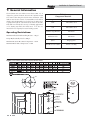
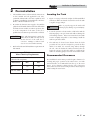
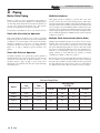
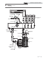
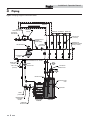
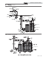
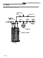
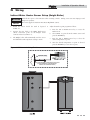
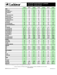
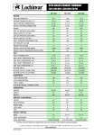
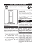
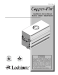
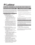
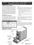
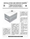
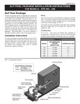
SSS-I-O Rev E Installation & Operation Manual Models: SSS031, SSS041, SSS051, SSS081, & SSS119 WARNING This manual must only be used by a qualified heating installer / service technician. Read all instructions before installing. Perform steps in the order given. Failure to comply could result in severe personal injury, death, or substantial property damage. Save this manual for future reference. Installation & Operation Manual Contents Hazard definitions . . . . . . . . . . . . . . . . . . . . . . . . . . . . . . . . . . . . . . . . . . . . . . . . 2 Please read before proceeding . . . . . . . . . . . . . . . . . . . . . . . . . . . . . . . . . . . . . . 3 1. General Information . . . . . . . . . . . . . . . . . . . . . . . . . . . . . . . . . . . . . . . . . . . . 4 2. Pre-Installation . . . . . . . . . . . . . . . . . . . . . . . . . . . . . . . . . . . . . . . . . . . . . . . . 5 3. Piping . . . . . . . . . . . . . . . . . . . . . . . . . . . . . . . . . . . . . . . . . . . . . . . . . . . . . . . . 6 Boiler Side Piping . . . . . . . . . . . . . . . . . . . . . . . . . . . . . . . . . . . . . . . . . . . . 6 Domestic Side Piping . . . . . . . . . . . . . . . . . . . . . . . . . . . . . . . . . . . . . . . . . 9 4. Wiring . . . . . . . . . . . . . . . . . . . . . . . . . . . . . . . . . . . . . . . . . . . . . . . . . . . . . . . . 13 5. Start-up and Check-out . . . . . . . . . . . . . . . . . . . . . . . . . . . . . . . . . . . . . . . . . . 15 6. Maintenance . . . . . . . . . . . . . . . . . . . . . . . . . . . . . . . . . . . . . . . . . . . . . . . . . . 15 Warranty . . . . . . . . . . . . . . . . . . . . . . . . . . . . . . . . . . . . . . . . . . . . . . . . . . . . . .16-17 Revision Notes . . . . . . . . . . . . . . . . . . . . . . . . . . . . . . . . . . . . . . . . . . . Back Cover Hazard definitions The following defined terms are used throughout this manual to bring attention to the presence of hazards of various risk levels or to important information concerning the life of the product. DANGER DANGER indicates an imminently hazardous situation which, if not avoided, will result in death or serious injury. WARNING WARNING indicates a potentially hazardous situation which, if not avoided, could result in death or serious injury. CAUTION indicates a potentially hazardous situation which, if not avoided, may result in minor or CAUTION moderate injury. CAUTION CAUTION used without the safety alert symbol indicates a potentially hazardous situation which, if not avoided, may result in property damage. NOTICE NOTICE indicates special instructions on installation, operation, or maintenance that are important but not related to personal injury or property damage. 2 Installation & Operation Manual Please read before proceeding WARNING NOTICE Installer – Read all instructions before installing. Perform steps in the order given. Have this indirect water heater serviced/inspected by a qualified service technician, at least annually. Failure to comply with the above could result in severe personal injury, death or substantial property damage. When calling or writing about the appliance – Please have the indirect water heater model and serial number from the indirect water heater rating plate. Consider piping and installation when determining appliance location. Any claims for damage or shortage in shipment must be filed immediately against the transportation company by the consignee. Factory warranty (shipped with appliance) does not apply to appliances improperly installed or improperly operated. WARNING If the information in this manual is not followed exactly, a fire or explosion may result causing property damage, personal injury or loss of life. This appliance MUST NOT be installed in any location where gasoline or flammable vapors are likely to be present. WHAT TO DO IF YOU SMELL GAS • Do not try to light any appliance. • Do not touch any electric switch; do not use any phone in your building. • Immediately call your gas supplier from a neighbor’s phone. Follow the gas supplier’s instructions. • If you cannot reach your gas supplier, call the fire department. • Installation and service must be performed by a qualified installer, service agency, or the gas supplier. WARNING Failure to adhere to the guidelines on this page can result in severe personal injury, death, or substantial property damage. When servicing the indirect water heater – • To avoid severe burns, allow the appliance to cool before performing maintenance. Indirect water heater operation – • Should overheating occur or gas supply fail to shut off, do not turn off or disconnect electrical supply to circulator. Instead, shut off the gas supply at a location external to the appliance. • Do not use this appliance if any part has been under water. The possible damage to a flooded appliance can be extensive and present numerous safety hazards. Any appliance that has been under water must be replaced. The following chart details the relationship of water temperature and time with regard to scald injury and may be used as a guide in determining the safest water temperature for your applications. APPROXIMATE TIME / TEMPERATURE RELATIONSHIPS IN SCALDS 120°F More than 5 minutes 125°F 1 1/2 to 2 minutes 130°F About 30 seconds 135°F About 10 seconds 140°F Less than 5 seconds 145°F Less than 3 seconds 150°F About 1 1/2 seconds 155°F About 1 second Hot Water Can Scald! • Water heated to temperatures for clothes washing, dish washing, and other sanitizing needs can scald and cause permanent injury. • Children, elderly, and infirm or physically handicapped persons are more likely to be permanently injured by hot water. Never leave them unattended in a bathtub or shower. Never allow small children to use a hot water tap or draw their own bath. • If anyone using hot water in the building fits the above description, or if state laws or local codes require certain water temperatures at hot water taps, you must take special precautions: • Use lowest possible temperature setting. • Install some type of tempering device, such as an automatic mixing valve, at hot water tap or water heater. Automatic mixing valve must be selected and installed according to valve manufacturer’s recommendations and instructions. • Water passing out of drain valves may be extremely hot. To avoid injury: • Make sure all connections are tight. • Direct water flow away from any person. Protection Must Be Taken Against Excessive Temperature and Pressure! --Installation of a Temperature & Pressure (T&P) relief valve is required. 3 Installation & Operation Manual 1 General Information The Lochinvar SSS series indirect water heater (FIG. 1-1) is designed to generate domestic hot water in conjunction with a hot water boiler using forced boiler water circulation. This indirect water heater consists of a 444 Stainless Steel tank in which a smooth 304 stainless steel coil is located. Boiler water is pumped through the coil and heats the water in the tank. This tank is not intended for use in pool heating applications or for heating any fluid other than water. It is also not intended for use in gravity hot water heating systems. Operating Restrictions: Maximum Allowable Tank Working Pressure - 150 psi Table 1A Component Materials Component Material Tank 444 Stainless Steel Coil 304 Stainless Steel Insulation (Top/Bottom) EPS Foam Insulation Sides EPS Foam Jacket Polypropylene Hand Hole Cover Gasket Silicone “O” Ring Design Hydrostatically Tested to 300 psi Maximum Domestic Hot Water Temperature - 190°F Maximum Boiler Water Temperature - 210°F Figure 1-1 Lochinvar SSS Series Indirect Water Heater 4 Installation & Operation Manual 2 1. Pre-installation The installation must conform with the instructions in this manual and all applicable local, state, provincial, and national codes, laws, regulations, and ordinances. Installations in Canada must conform to B149.1 or B149.2 Installation Codes. 2. 1. Figure 1-1 on page 4 shows the weights of all the tanks filled with water. Make sure that the location chosen for the tank is capable of supporting it. Be certain the domestic water supply to the tank has physical and chemical characteristics that fall within the limits shown in Table 2A. Where questions exist as to the composition of the water on the job, a qualified water treatment expert should be consulted. 2. Water with characteristics outside the limits shown in Table 2A may severely shorten the life of the tank due to corrosion. Damage to tanks in such cases is not covered under warranty. Locate the system in a location where a leak in the tank, the adjacent piping, or an open T & P valve will not damage the surrounding structure. If the area around the desired tank location is highly susceptible to water damage, install the tank in a pan with a drain. 3. The tank may be located some distance from the boiler provided the zone system is designed to provide the flow called for in Table 3A - Pressure Drop Values, through the coil. Also, the further the tank is from the boiler, the longer the response of the boiler will be to a call from the tank zone. Insulate piping between the boiler and the tank. CAUTION 3. Locating the Tank Read and understand all installation requirements in this manual. Table 2A Water Chemistry Requirements Water used in the tank must have characteristics falling within the following limits: Characteristic Min. Max. Ph 6.0 8.0 Chloride (PPM) 0.0 80.0 WARNING Failure to properly support the tank could result in property damage or personal injury. Recommended Clearances The installation location must provide adequate clearances for servicing and proper operation of the water heater. A 12 inch vertical clearance is recommended from the top of the water heater. A zero clearance is allowed for the sides of the water heater. However, boiler and servicing clearances must be figured when locating the water heater. 5 Installation & Operation Manual 3 Piping Boiler Side Piping DHW Prioritization Figures 3-1 thru 3-3 show typical boiler side piping for several common situations. Regardless of which system is used it is imperative that the flow rates called for in Table 3A on page 6 are developed through the coil. This requires properly sized piping and a properly sized pump. This piping system is designed to provide direct hot water priority over the other zones in the heating system. When there is a Domestic Hot Water (DHW) call for heat, the Knight control will shut off the boiler circulator and activate the domestic hot water circulator. Once the DHW demand is satisfied, the boiler circulator will be readjusted as demand requires. The circulator must be large enough to move the boiler water through the coils. The recommended piping for a DHW priority system is depicted in FIG. 3-3 on page 8. The system shown in FIG’s 3-1 thru 3-3 are described below: Zone with Circulator to Aquastat This system is like the circulator zone system on a straight heat job except that one of the zones goes to the tank instead of radiation. As on any circulator zone system check valves should be installed in each zone to prevent unwanted circulation through zones which are not calling for heat. Figure 3-1 on page 7 illustrates typical circulator zone piping. Zone with Valve to Aquastat As with the circulator zone system, this system is just like a standard heating zone system except that one of the zones is connected to the tank coil as shown in FIG. 3-2. The circulator must be large enough to move boiler water through the coil regardless of the flow rate required through the heating zones. Multiple Tank Connections (Boiler Side) Multiple tank installations must be done in the “reverse-return” manner. The reason for this is to create the same pressure drop (and therefore, the same flow) through the coil of each tank. The boiler manifold piping must be sized so that each coil has the flow rate called for in Table 3A below. For example, if two tanks are to be manifolded together, the circulator and zone piping common to both tanks must be capable of moving 16 GPM (2 x 8 GPM), see FIG. 3-4 on page 9. Because the pressure drop through tank coils varies from size to size, it is hard to predict the flow rate that will be developed through each coil when two tanks of different sizes are placed in the same manifold. For this reason it is best not to mix tanks of two different sizes in the same zone if their recovery is critical. Table 3A Pressure Drop Values Coil Length (FT) Tube Diameter (IN) SSS031 22.0 SSS041 Model Pressure Drop (FT/HD) 8 GPM 12 GPM 16 GPM 20 GPM 1 1/4 1.4 3.0 5.1 7.8 27.6 1 1/4 1.7 4.0 6.4 9.8 SSS051 32.8 1 1/4 2.0 4.4 7.6 11.7 SSS081 49.2 1 1/4 N/A 6.3 10.9 16.7 SSS119 65.6 1 1/4 N/A N/A 15.3 23.5 6 Installation & Operation Manual 3 Piping (continued) Figure 3-1 Piping Diagram Zoned with Circulators ZONE #1 PRESSURE REDUCING VALVE PRESSURE GAUGE ZONE #2 ZONE #3 ZONE #4 BACKFLOW PREVENTER ZONE CIRCULATORS (TYPICAL) MAKE UP WATER SYSTEM SUPPLY SENSOR (WHEN USED) AIR SEPARATOR EXPANSION TANK NOT TO EXCEED 4 PIPE DIA. OR A MAXIMUM OF 12” APART DRAIN POINT (TYPICAL) HOT WATER OUT BOILER CIRCULATOR BALL VALVE (TYPICAL) FLOW CHECK VALVE ANTI-SCALD MIXING VALVE COLD WATER IN RELIEF VALVE RECIRCULATION LOOP AQUASTAT UNION (TYPICAL) TEMPERATURE / PRESSURE GAUGE PRESSURE RELIEF VALVE SOLUTION BOILER SQUIRE 7 Installation & Operation Manual 3 Piping Figure 3-2 Piping Diagram Zoned with Valves ZONE #1 PRESSURE REDUCING VALVE PRESSURE GAUGE ZONE #2 ZONE #3 BACKFLOW PREVENTER ZONE #4 ZONE VALVES (TYPICAL) SYSTEM SUPPLY SENSOR (WHEN USED) MAKE UP WATER AIR SEPARATOR DIFFERENTIAL PRESSURE BYPASS VALVE (IF USED) SYSTEM CIRCULATOR EXPANSION TANK NOT TO EXCEED 4 PIPE DIA. OR A MAXIMUM OF 12” APART DRAIN POINT (TYPICAL) HOT WATER OUT BOILER CIRCULATOR BALL VALVE (TYPICAL) ANTI-SCALD MIXING VALVE COLD WATER IN RELIEF VALVE RECIRCULATION LOOP AQUASTAT UNION (TYPICAL) TEMPERATURE / PRESSURE GAUGE PRESSURE RELIEF VALVE 8 SOLUTION BOILER SQUIRE Installation & Operation Manual 3 Piping (continued) Figure 3-3 Knight Boiler Primary / Secondary Piping PRESSURE REDUCING VALVE BACKFLOW PREVENTER PRESSURE GAUGE MAKE UP WATER AIR SEPARATOR SYSTEM SUPPLY SENSOR TO SYSTEM BALL VALVE (TYPICAL) NOT TO EXCEED 4 PIPE DIA. OR A MAXIMUM OF 12” APART SYSTEM CIRCULATOR BOILER CIRCULATOR FROM SYSTEM ANTI-SCALD MIXING VALVE COLD WATER IN EXPANSION TANK DRAIN POINT (TYPICAL) DOMESTIC HOT WATER CIRCULATOR RECIRCULATION LOOP TANK SENSOR / LIMIT UNION (TYPICAL) TEMPERATURE / PRESSURE GAUGE DRAIN PRESSURE RELIEF VALVE DRAIN POINT (TYPICAL) BOILER INDIRECT TANK Figure 3-4 Multiple Tank Connections TANK SENSOR / LIMIT 9 Installation & Operation Manual 3 Piping Domestic Side Piping Basic Domestic Piping Figure 3-5 on page 12 shows typical domestic water piping for a tank. All components except the control are provided by the installer. The function of the components shown are as follows: a. Shut-off valves (recommended) - Use to isolate the tank for servicing. b. Backflow Preventer (required by some codes) - Use to prevent water from backing out of the tank in the event that inlet water pressure drops. c. Expansion Tank (required when a backflow preventer is used) - This expansion tank absorbs the increased volume caused by heating water. If a backflow preventer is installed, this expansion tank is required because the increased water volume will otherwise have no place to go and the T & P valve will open. Use an expansion tank designed for use on domestic water systems. Refer to the expansion tank manufacturer’s literature for the proper size expansion tank to use. NOTICE If an expansion tank is used, do not put any valves between the expansion tank and tank inlet. Tank Piping with a “Temperature Limiting Valve” Usually, the maximum temperature of the outlet water will stay near the setting of the tank control. In some cases, however, hot water usage patterns can cause the outlet water temperature to rise significantly above the control setting. The temperature of water going to the fixtures may be more carefully controlled through the use of a thermostatic mixing valve. This device blends a controlled amount of cold water with the hot water leaving the tank so that water at a more constant temperature exits the mixing valve. Anti-scald mixing valve piping is illustrated in FIG.’s 3-1 thru 3-3. WARNING An anti-scald mixing valve does not eliminate the risk of scalding. * Set the tank thermostat as low as practical. * Feel water showering. * If anti-scald or anti-chill protection is required, use devices specifically designed for such service. Install these devices in accordance with their manufacturer’s instructions. before bathing or Multiple Tank Domestic Water Piping d. Unions (optional) - Use to disconnect the tank in the unlikely event that this is necessary. e. Drain (required) - Used to drain the tank for inspection or servicing. Figure 3-4 illustrates the recommended method of piping the domestic water side of several tanks together. All tanks are piped in true parallel. Total domestic pipe lengths must be the same from point of tank exit to the common “T” to ensure an equal draw from each tank. Each tank must have its own T&P valve. It is recommended that each tank be equipped with its own isolation valves, unions, and drains so that one tank may be removed from the system. If local codes require a backflow preventer, check with the appropriate authority to find out whether one backflow preventer may be used for tanks or each tank must be equipped with its own backflow preventer. If each tank must have its own backflow preventer, each tank must also have its own expansion tank. If a common backflow preventer is permitted, an expansion tank must be sized to accommodate the expansion volume of all tanks. 10 Installation & Operation Manual 3 Piping (continued) Domestic Water Piping for Distant Fixtures NOTICE In some cases the furthest fixture may be quite distant from the tank. In such an installation the configuration shown in FIG. 3-5 would result in an unacceptable delay before hot water reaches these distant fixtures. Even if all the fixtures are relatively close to the tank, the building owner may want hot water at all fixtures as soon as they are opened. NOTICE A solution to this problem is that a pipe runs from the furthest fixture on each branch back to the return of the tank. A small bronze circulator is mounted in this line and is wired so as to run continuously. A check valve in this line permits flow towards the tank inlet only. When no fixtures are drawing water, the bronze circulator moves hot water from the tank to the end of the branch just below the last fixture, then back to the inlet of the tank via the return pipe. When a fixture is opened, hot water is already out in the branch very close to the fixture and hot water appears at it almost immediately. The check valve prevents cold water in the tank’s inlet pipe from passing around the tank and heading directly to the fixture. Because hot water is always circulating in the hot water branch the entire branch should be insulated to prevent excessive heat loss. Temperature & Pressure (T&P) Relief Valve CAUTION To reduce the risk of excessive pressures and temperatures in the water heater, install temperature and pressure protective equipment required by local codes, but no less than a combination temperature and pressure relief valve certified by a nationally recognized testing laboratory that maintains periodic inspections of production of listed equipment or materials, as meeting the requirements for Relief Valves and Automatic Gas Shutoff Devices for Hot Water Supply Systems, ANSI Z21.22. This valve must be marked with a maximum working pressure of the water heater. • • Every Lochinvar Indirect Water Heater must be protected with a T&P relief valve. Determine T&P relief valve size by the following specifications, unless they conflict with local codes: - SSS031/041 - 3/4" NPT with an AGA Rating of 100,000 Btu/hr. - SSS051/081/119 - 3/4" NPT with an AGA Rating of 200,000 Btu/hr. For proper operation of the T&P and to prevent the T&P from activating due to boiler water temperature, use a T&P relief valve with extended element. The recommended element length is 8 inches. The Lochinvar SSS series water heaters will absorb less than 200,000 Btu/hr when domestic water outlet temperature is 210°F and boiler water supply temperature is 240°F. Listed outputs are based on ASME Section VIII Interpretation VIII-1-86-136. Check with local codes for applicability. Standard Installation • Install the T&P relief valve in the connection marked “Relief Valve”. T&P Relief Valve Discharge Piping T&P relief valve discharge piping must be: - made of material serviceable for a temperature of 250°F or greater. - directed so that hot water flows away from all persons. - directed to a suitable place for disposal. - installed so as to allow complete draining of the T&P relief valve and discharge line. - terminated within 12" of the floor. T&P relief valve discharge piping must not be: - excessively long. Using more than two (2) elbows or 15 feet of piping can reduce discharge capacity. - directly connected to a drain. Terminate discharge piping within 6" from drain. Refer to local codes. - subject to freezing. WARNING Do not install any valve between T&P relief valve and tank connection or on T&P relief valve discharge piping. Improper placement and piping of T&P relief valve can cause severe personal injury, death or substantial property damage. CAUTION T&P relief valve is not intended for constant duty, such a relief of pressure due to repeated normal system expansion. Correct this condition by installing a properly sized expansion tank in domestic water system. Refer to expansion tank manufacturer’s installation instructions for proper sizing. 11 Installation & Operation Manual 3 Piping Figure 3-5 Recommended Domestic Water Piping 12 Installation & Operation Manual 4 Wiring Indirect Water Heater Sensor Setup (Knight Boiler) CAUTION NOTICE 1. 2. 3. Label all wires prior to disconnection when servicing controls. Wiring errors can cause improper and dangerous operation. The sensor supplied contains an Auto Reset High Limit (195°F). Install the sensor inside the tank as depicted in FIG. 4-1. 4. Adjust the tank set point program as follows: a. Connect the wire leads to the DHW Tank Sensor (AUX) connection point on the Knight boiler connection board (see FIG. 4-1). Press the UP or DOWN arrow key to access the Menu Screen. b. Select DHW set point from the Menu Screen and press the ENTER key. The Knight boiler will automatically read the sensor and default the tank temperature setting to 125°F. c. Press the UP or DOWN arrow key to select the desired temperature set point. d. Once the desired temperature set point is selected, press the ENTER key to store the set point. Figure 4-1 IDW Controlled Using Tank Sensor AUX. SENSOR OR DHW TANK SENSOR DHW TANK SENSOR / AUTO RESET HIGH LIMIT (PLACE SENSOR IN TANK BULBWELL & SNAP CLIP OVER BULBWELL) 13 Installation & Operation Manual 4 Wiring IDW Controlled Using Aquastat and Zone Circulator / Valve 1. Install Aquastat to tank. Aquastat control (TST1085) can be ordered from your local Lochinvar distributor. 2. Connect Aquastat to the zone controller for the Indirect Water Heater Zone. 3. Adjust Aquastat to the desired temperature. Figure 4-2 Wiring for Zone Control 14 Installation & Operation Manual 5 Start-up and Check-out 1. Make sure the system is free of leaks and that air is purged from the system. CAUTION Fix any leaks found before proceeding further. Leakage from the boiler piping can result in severe damage to the boiler. 2. Many soldering fluxes contain Zinc Chloride which can cause severe corrosion damage to stainless steel. After completing all domestic water connections, flush the indirect water heater thoroughly before leaving the installation. This is particularly important if the indirect water heater will be unused for an extended period of time after installation. Flush the indirect water heater by drawing at least three times its volume from the tank. 4. Make sure that each zone valve or circulator operates when, and only when, its thermostat calls for heat. Let each zone operate long enough to purge any remaining air from the system. 5. Set the indirect water heater to the desired temperature. Because hot water presents a scald hazard, it is best to set the thermostat at 120°F or lower and raise it only if necessary to provide adequate hot water. 6. Re-enable the burner and allow the boiler to operate. Make sure that the boiler shuts down when the indirect water heater is satisfied. 3. Make sure that all electrical connections are made correctly and that no exposed high voltage wiring is present. 6 Maintenance The Lochinvar SSS series indirect water heater is an extremely simple device and as such requires very little maintenance. There are, however, several items which should be checked out on an annual or as needed basis to ensure a reliable supply of hot water: * On an annual basis, remove the black cover over the hand hole and make sure the hand hole cover is leak-tight. * Make sure that the rest of the boiler and domestic water piping is free of leaks. * If there is an oil lubricated circulator in the system, make sure it is lubricated as called for by the circulator manufacturer. * The indirect water heater depends upon the boiler for a source of heat and is therefore only as reliable as the boiler. Make sure that the boiler is maintained in accordance with the boiler manufacturer’s instructions. * If a water treatment system is required to keep the water chemistry within the parameters shown in Table 2A (see Section 2 - Pre-Installation), make sure that this system is properly maintained. 15 LIMITED LIFETIME INDIRECT WATER HEATER WARRANTY WHAT DOES THIS LIMITED WARRANTY COVER? WHAT IS THE PERIOD OF COVERAGE? This limited lifetime warranty covers the stainless steel tank, stainless steel heat exchanger coil and component parts for leakage or other malfunction caused by defects in materials and/or workmanship. It extends to the first buyer and to any subsequent owner(s) as long as the water heater remains installed at its original place of installation. This limited warranty is effective 60 days from the date of manufacture as determined by the serial number. Model number and serial number are found on the rating plate affixed to the boiler. Stainless steel tanks and stainless steel heat exchanger coils are warranted against leakage and thermal shock for the lifetime of the installation. All parts are warranted for one (1) year. WHAT DOES THIS LIMITED WARRANTY NOT COVER? 1. This limited warranty does not cover leakage or other malfunction caused by: a. Excessive use and specifically, non-residential use. b. Defective Installation, and specifically, any installation which is made: I) in violation of applicable state or local plumbing, housing or building codes, or II) without a certified American Gas Association, ASME, or comparable combination temperature and pressure relief valve, or III) contrary to the written instructions furnished with this unit. c. Adverse local conditions, and specifically, sediment or lime precipitate in the tank or corrosive elements in the atmosphere. d. Misuse, and specifically, operation and maintenance contrary to the written instructions furnished with the unit, , disconnection, alteration or addition of non-approved components or apparatus,operation with fuels or at settings other than those set forth on the rating plate, or accidental or other exterior damage. 2. This warranty also does not cover: a. Production of noise, taste, odors, discoloration or rusty water. b. Damage to surrounding area or property caused by leakage or malfunction. c. Costs associated with the replacement and/or repair of the unit, including: I) any freight, shipping or delivery charges II) any removal, installation or re-installation charges III) any material, and/or permits required for installation, re-installation or repair IV) charges to return the defective water heater and/or component part to the manufacturer. WHAT IS THE PERIOD OF COVERAGE? 16 *Any water heater used for other than a single family housing unit will be covered for five years on tank and one year on parts regardless of any other warranty period specified. All replacement tanks and parts carry the balance of the original warranty, i.e. if an original five (5) year warranted water heater develops a leak due to defects in materials/workmanship after three (3) years, the replacement unit is warranted for the balance remaining on the original five (5) year warranty, or two (2) year in this example. WHAT IS THE DURATION OF THE IMPLIED WARRANTY? Any implied warranty, including the warranty of merchantability imposed on the sale of the water heater under the laws of the state of sale are limited in duration to one year from date of original installation. HOW DOES STATE LAW RELATE TO THE WARRANTY? Some states do not allow: 1. Limitations on how long an implied warranty lasts. 2. Limitations on incidental or consequential damages. The above limitations or exclusions may not apply to you. This warranty gives you specific legal rights, and you may also have other rights which vary from state to state. LIMITED LIFETIME INDIRECT WATER HEATER WARRANTY (CONTINUED) WHAT WILL WE DO TO CORRECT PROBLEM? If a defect occurs within the warranty period, we will: 1. Provide a comparable replacement water heater of our manufacture, (or at our option repair) any unit which develops a leak in the stainless steel tank or heat exchanger coil within the warranty period. To obtain a replacement, you must have the rating plate from the defective unit.. 2. Provide a replacement part (or at our option repair) any part which fails to function within the part warranty period. To obtain the replacement, you must turn in the defective part. We do reserve the right to verify any claims of defect by inspection. WHAT SHOULD YOU DO TO KEEP THE WARRANTY IN EFFECT? To facilitate warranty service, you should: 1. Follow all instructions enclosed with the product. 2. Retain all bills of sale or receipts for proof of installation, etc. 3. Contact your installer or dealer as soon as any problem or defect is noticed. 4. When necessary, allow our chosen representative, to inspect the unit. 5. For your reference, fill in the Model and Serial Number found on the unit’s Rating Plate: NOTE: If government regulations require the replacement water heater to have features not found on the original water heater, you will be required to pay the difference in price represented by the required features. Model Number WHAT WILL WE NOT DO? Serial Number We will not: Date of Installation 1. Repair or replace any water heater, or part, subject to conditions outlined in “What Does This Limited Warranty Not Cover?” 2. Reimburse any costs associated with repair and/or replacement. 3. Replace and/or repair any water heater without complete model/serial number. 4. Replace any water heater without prior receipt of actual rating plate from the appliance. SAFETY WARNING Water heaters are heat producing appliances and to avoid damage or injury in the event of possible overheating of the outer jacket: 1. No materials should be stored against the jacket. 2. Care should be taken to avoid unnecessary contact (especially by children) with the jacket. UNDER NO CIRCUMSTANCES SHOULD FLAMMABLE MATERIALS, SUCH AS GASOLINE OR PAINT THINNERS, BE USED OR STORED IN THE VICINITY OF THE HEATER OR IN ANY LOCATION FROM WHICH FUMES COULD REACH THE HEATER. For your comfort, enjoyment and safety, please read the enclosed operation instructions carefully. Lochinvar Corporation • 300 Maddox Simpson Pkwy • Lebanon, TN 37090 • 615-889-8900 / Fax: 615-547-1000 www.Lochinvar.com SS-WAR-01 ©–12/06—Printed in U.S.A. 17 Notes 18 Notes 19 Revision Notes: Revision B (SSS-I&O-Rev B) reflects edits and additions made to the piping diagrams. Revision C (SSS-I&O-Rev C) reflects edits made to the piping diagrams, the DHW Tank Sensor (AUX) and the addition of the warranty. Revision D (ECO #C02870) reflects the addition of the scald chart on page 3. Revision E (ECO #C02918) reflects tank sensor changes on FIG.’s 3-3, 3-4, and 4-1 on pages 9 and 13 along with the addition of a note on page 13. SSS-I-O Rev E 3/09 - Printed in U.S.A.