1
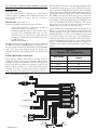
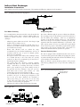
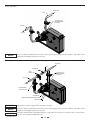
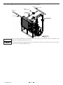
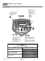
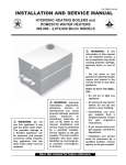
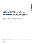
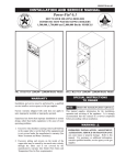
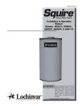
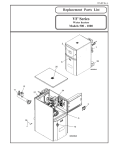
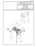
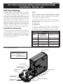
INS70057 Rev C
XLP POOL PACKAGE INSTALLATION INSTRUCTIONS
FOR MODELS: XPN 399 – 800
XLP Pool Package
The XLP pool package system is a high efficiency commercial
condensing boiler, pre-piped package system from the factory
to an indirect heat exchanger. This pool heater is a low
temperature operating system designed to take advantage of
the stainless steel heat exchanger and condensing operating
temperatures to ensure the highest efficiency possible. The
XLP is designed around a predetermined flow set by the
manufacturer between the boiler and the indirect heat
exchanger. The XLP operates off the pool system pump itself
which will continually supply water to the indirect heat
exchanger. This means there is no need to purchase a
dedicated circulator to deliver water to this package system.
Installation Instructions
To achieve the optimum operating efficiency of your XLP it
is recommended that you keep the pool water flow of each
appliance within plus or minus five gallons per minute of the
recommended flow as stated in Table A. Low flow through
the indirect heat exchanger will result in elevated
temperatures supplied to the pool.
Piping
Pool / spa connections to the indirect heat exchanger are SCH 80
CPVC. Pool water is designed to flow from right to left standing
in front of the boiler (factory installed sensor is on the inlet side
of the indirect heat exchanger, see FIG. 8).
The supply and return water piping to the indirect heat exchanger
shall be no smaller than 2.5" for models 399 - 600 and 3" for
models 700 - 800.
Throttling Valve
A ΔT of 8° - 10°F across the indirect heat exchanger is
recommended. Throttling valves are used to set the flow through
the indirect heat exchanger (standard gate valves are acceptable).
TABLE A
MODEL
RECOMMENDED
SYSTEM
WATER FLOW
CONNECTION SIZE
399
93 GPM
2.5"
500
117 GPM
2.5"
600
142 GPM
2.5"
700
166 GPM
3"
800
202 GPM
3"
FIG. 1_Component Location
Air Inlet Connection
RECOMMENDED CLEARANCES:
BOILER - SEE KNIGHT XL BOILER
I & O MANUAL
INDIRECT HEX -- ALLOW 18” FOR
SERVICE ON ALL SIDES
Gas Inlet
Flue Connection
Pressure Reducing
Valve / Auto Fill Valve
System Sensor
Location
Cupro-Nickel Pool
Heat Exchanger
Skid Mounted on
Steel Frame
Condensate Drain
Relief Valve
T&P Gauge
Flow Switch
Boiler Pump
399,000 to 800,000 BTUs
Expansion Tank
The system can be installed in either a Full Flow or Diverted
Flow orientation:
Full Flow (reference FIG. 6)
If the total system flow of the swimming pool or spa system is
within five gallons per minute of the recommended system water
flow as shown in Table A on page 1, this type of system is
recommended.
Diverted Flow (reference FIG.’s 7 & 8)
Criteria for installing a diverted flow system is as follows:
•
If the total system flow is greater than the amount
required by the indirect heat exchanger.
•
Installations with temperatures in excess of 95°F. This is
necessary so the pool high limit will not trip. No water
should enter the pool / spa in excess of 110°F. If the heat
exchanger pool outlet is in excess of 110°F the water must
be tempered down.
•
Multiple unit installation.
Example: Total system flow is 500 gallons per minute (GPM). If
two XLP Pool Packages (800,000 Btu/hr) were installed, each of
the pool packages would require 202 GPM for a total of 404 GPM
of the pool water being diverted through the indirect heat
exchangers while the other 96 GPM would be diverted back to the
pool.
The limit will be mounted in a 3/8" NPT tapped fitting installed
in the filtration system piping or it may be installed directly into a
tapped opening in the PVC filter system piping. Turn off the filter
system pump when installing the auxiliary limit in the filtration
system piping. Tapped openings can be added to the PVC pipe by
first drilling 9/16" pilot holes in the PVC pipe at least three feet
downstream of the point where the heated water from the indirect
heat exchanger is added to the filter piping. The drilled pilot holes
can now be carefully threaded with a 3/8" NPT tap. After the pipe
threads have been cut into the PVC pipe wall the limit and
bulbwell can be inserted into the tapped openings.
Apply a small amount of a high quality RTV silicone sealant to the
threads to prevent leaks and install the limit and bulbwell into the
threaded opening in the pipe. Install the limit control and
bulbwell and tighten to seal. Do not over tighten either part into
the threaded opening in the PVC pipe. Over tightening can
damage the parts and/or strip the threads cut into the plastic pipe.
Wire the 110°F limit into the pool heater control circuit as shown
in FIG. 2. If additional wire length is needed, use 18 gauge wire
for distances up to 30 feet. For longer distances, size the wire per
Table B.
TABLE B
Remote Wire Connection
Auxiliary Mixed Water Limit Control
Ensure that the auxiliary 110°F mixed water limit control is
installed in the filter system piping. Install the auxiliary limit a
minimum of three feet downstream from the point where the
heated water from the indirect heat exchanger is added to the
filtration system (see FIG.’s 6-8). If the water leaving the heat
exchanger is in excess of 110°F a bypass must be installed to
temper the water below 110°F before re-entering the pool/spa.
WIRE GAUGE
MAXIMUM ALLOWABLE
LENGTH
12 GA
100 ft.
14 GA
75 ft.
16 GA
50 ft.
18 GA
30 ft.
FIG. 2_Low Voltage Connections
AUX. DEVICE
RELAY
AUX. DEVICE
24VAC
PILOT SUPPLY
GND
AUX. DEVICE
PROVING
110° HIGH LIMIT SENOR
GAS PRESSURE
SWITCH
FLOW
SWITCH
ALARM
CONTACTS
NO
DHW THERMOSTAT
R ROOM THERMOSTAT /
W ZONE CONTROL
LOW WATER
CUTOFF
FLOW SWITCH
CN4
RUNTIME
CONTACTS
COM
CN5
CN2
SYSTEM
SENSOR
DHW TANK
SENSOR
TO REMOTE ENABLE
(JUMPER REQUIRED IF NOT USED)
OUTDOOR
SENSOR
SHIELD GROUND
A
SEQUENCING
B
SHIELD GROUND
0-10VDC
GND
SYSTEM SUPPLY SENSOR
CN3
EXTERNAL
CONTROL
CN1
(AUX) DHW SENSOR
BUILDING
MANAGEMENT
SYSTEM
LOW WATER
CUTOFF
SHIELD
SHIELD
FROM
PREVIOUS
BOILER
INS70057 Rev C
A
B
A
B
2
TO
NEXT
BOILER
Indirect Heat Exchanger
Installation Instructions
Heat exchangers should be installed downstream of the pumping and filtration equipment (reference FIG. 3).
FIG. 3_Pumping and Filtration Equipment
TO POOL
CHLORINATOR
(DOWNSTREAM)
TOP VIEW
FROM POOL
SYSTEM PUMP
FILTRATION
Filling the System
Pool Water Chemistry
It is essential that the instructions in this section along with the
Ryznar Stability Index and/or Calcium Stability Index are
followed to prevent corrosion / erosion of the indirect heat
exchanger:
-
-
-
-
-
-
The boiler is filled through the pressure reducing auto-fill valve.
The operating pressure of this system is 15 psi between the heater
and the indirect heat exchanger. There are no adjustments
necessary to the fill valve cartridge (factory set). The expansion
tank is set at 20 psi. It is necessary to check the pressure of the
expansion tank when annual maintenance is performed. The
boiler system operates off a city or potable water system which
feeds a closed loop system. A hard line is piped from the potable
water supply to the pressure reducing valve. This water is to
remain on at all times when the system is in operation.
Always keep pH to within correct levels. The ideal pool pH
should be kept to within 7.4 to 7.6.
Under no circumstances should the pH fall below 7.2 or
rise above 7.8 (see FIG. 4). Check on a day-to-day basis. Alter
pool condition as necessary.
Ensure that chlorine levels are within the range
recommended by the chemical manufacturer and are in
accordance with the type of pool, for example; private,
hotel, school or municipal.
If a bypass is fitted to the indirect heat exchanger circuit,
it is essential that any or all of the valves are correctly
positioned to allow the recommended pool water flow to
pass through the heat exchanger.
The system filter unit should be checked regularly,
especially sand filters (to detect sand and diatomaceous
earth). Sand filters, if working incorrectly, can allow
sand to pass around the pool circuit causing erosion of
the pipework and heat exchanger. Keep the pool free
from debris such as leaves, grass cuttings, etc. This
foreign matter can cause decay and increase pH.
It is essential that the correct amount of chlorine dosage
is added to the pool. To allow proper dispersion of the
dose in the pool water, distribute the chemicals to
various areas of the pool. Do not dose in one area only,
as this will create high acidic areas which can cause
corrosion / erosion of the pool equipment.
Chlorinator should be installed downstream of the XLP.
Pressure Reducing Valve
The valve is equipped with a fast-fill feature that can be used to
override normal operation when filling and purging the system.
To activate fast-fill, push and hold down the fast-fill knob on top
of the cartridge as shown in FIG. 5.
Relieve air from the system through operation of the pressure
relief valve by pulling the lever on top of the valve, causing it to
open.
FIG. 5_Pressure Reducing Auto-Fill Valve
PUSH CAP DOWN TO
ACTIVATE FAST FILL
FIG. 4_pH Scale
7.4 - 7.6
INS70057 Rev C
3
FIG. 6_Full Flow
FROM POOL
CPVC
FACTORY POOL
RETURN SENSOR
LOCATION
110° LIMIT
TO POOL
NOTICE
Please note that these illustrations are meant to show system piping concept only, the installer is responsible for all
equipment and detailing required by local codes.
FIG. 7_Bypass (if flow is greater than required by heat exchanger)
FROM POOL
CPVC
FLOWMETER
VALVE
THROTTLING
FACTORY POOL
RETURN SENSOR
LOCATION
110°F LIMIT
TO POOL
RECOMMENDED
ISOLATION VALVE
FLOWSWITCH
TEMPERATURE AND PRESSURE GAUGE
RELIEF VALVE
NOTICE
Adjust valves to provide suggested flow per Table A on page 1.
NOTICE
Please note that these illustrations are meant to show system piping concept only, the installer is responsible for all
equipment and detailing required by local codes.
NOTICE
System flow should always remain higher than the required flow for the boiler(s) when the boiler(s) is in operation
to prevent short cycling and high limit issues.
INS70057 Rev C
4
FIG. 8_Bypass Multiple Units (if flow is greater than required by heat exchanger)
TO POOL
FROM POOL
110° F LIMIT
VALVE
THROTTLING (3X)
FLOWMETER (3X)
(OPTIONAL)
CPVC PIPING
RECOMMENDED
ISOLATION VALVE
FACTORY POOL
RETURN SENSOR
LOCATION
NOTICE
Please note that these illustrations are meant to show system piping concept only, the installer is responsible for all
equipment and detailing required by local codes.
NOTICE
System flow should always remain higher than the required flow for the boiler(s) when the boiler(s) is in operation
to prevent short cycling and high limit issues.
INS70057 Rev C
5
Press the ENTER key to access these parameters. Use the UP
arrow key to access parameter H2 SH Source. Press the ENTER
key to access this parameter. Use the DOWN arrow key to select
Cascade. Press the ENTER key to program this into the control.
Press the UP arrow key to select the parameter H3 BLR Address.
Press the ENTER key to access this parameter. Each unit in the
Cascade system must be programmed with its own address. The
boiler designated as the Leader will have an address of 0. The
remaining boilers in the Cascade will be Members and have
addresses from 1 - 7. Use the UP and DOWN arrow keys to select
the appropriate address. Press the ENTER key to program this
into the control.
Press the MENU key twice to exit the control parameters. Repeat
this procedure for all boilers in the Cascade, designating the
Leader control and the Member controls.
Cascade
When multiple boilers are installed, they can be wired together in
a cascade sequence. A maximum of eight boilers can be controlled
from a single control. In this application one boiler would be
designated as the Leader control and all others would be
designated as Member controls.
If the water temperature at the inlet side of the indirect heat
exchanger sensor is less than the setpoint + the turn-off offset the off-on differential, then the control will initiate a call for heat
on the Cascade (see the Knight XL Service Manual for an
explanation of the offset and differential). The Leader will
energize the lead boiler on the Cascade. For a new startup this will
be the Leader boiler.
The boiler will fire at its ignition speed and will then modulate its
firing rate to maintain the setpoint. If the first boiler reaches 100%
of its firing rate, the Leader will calculate at what point the second
boiler could fire at 20% of its firing rate. At this point, the Leader
will fire the second boiler on the Cascade. For a new startup, this
would be the first Member boiler. The boiler will fire at its ignition
speed and will then modulate its firing rate to maintain the
setpoint.
If the setpoint still cannot be met, the Leader will continue firing
more Members until either the heat demand is met or all boilers
on the Cascade are firing. As the heat demand decreases, the last
boiler on will modulate down to 20% of its firing rate. Once the
demand for that boiler is zero, it will shut down. As the heat
demand decreases further, the second to last boiler will modulate
down and shut off. This will continue until the demand is
satisfied and all boilers are shut off.
XLP Pool Setup
To access the Installer setting press and hold the Menu/Exit key
until it requires the installer’s code. Proceed and enter #5309
(reference Table C on page 7).
NOTE: NA = No adjustment necessary.
Standalone Operation
B: Temperature Settings
B1: Pool Setpoint (pool temperature)
B2: SH Min Setpoint (pool temperature minimum)
B3: Max Setpoint (factory set at 104°F)
B4: SH Offset (2°F minimum) Number of degrees above the
setpoint that the boiler will turn off.
B5: SH Differential (4°F minimum) Number of degrees
below the turn off temperature the boiler must see before
the boiler will turn on.
Wiring of the Cascade
When wiring the boilers for Cascade operation, select one boiler
as the Leader boiler. The remaining boilers will be designated as
Members. See “Configuration of the Cascade” for a detailed
explanation of this procedure.
Communication between the Leader boiler and the Member
boilers is accomplished by using shielded, 2-wire twisted pair
communication cable. Connect one of the twisted pair wires to
terminal A on each of the Low Voltage Connection boards
(FIG. 2), and the other wire of the twisted pair to terminal B on
each of the Low Voltage Connection Boards. Connect the shield
wires to one of the shield ground terminals on the Low Voltage
Connection Boards. If more than two boilers are on the Cascade,
daisy chain the wiring from the Sequencing terminals on the
second boiler to the Sequencing terminals on the third boiler,
then from the third to the forth, and so on. The connections
between boilers can be made in any order, regardless of the
addresses of the boilers. Try to keep each cable as short as
possible.
Example: Setpoint 78°F
Offset = 2 Boiler OFF at 80°F
Differential = 4 Boiler ON at 76°F
Cascade Multiple Units Together
B: Temperature Settings
B1: Pool Setpoint (pool temperature)
B2: SH Min Setpoint (pool temperature minimum)
B3: Max Setpoint (factory set at 104°F)
H: Control Modes
Cascade
H1: SH CNT Sensor NA
H2: Control Source (Cascade)
H3: Cascade Addr (Leader 0) (Member 1,2,3, etc.,)
H4: Max Cascade Setpoint
H5: Cascade Offset (2°F minimum, this is the warmest the
pool will ever be above temperature)
H6: Cascade Differential (This parameter determines how
much the temperature must go below the turn off
temperature (setpoint + offset) before the Lead boiler turns
on. Four degrees is the tightest this setting can be.)
Configuration of the Cascade
When installed in a Cascade system, the individual controls must
be programmed for cascade operation. This is accomplished by
accessing the control parameters.
Input the Installer code as described in the XLP Pool Setup Section
(this page). Once the control parameters have been accessed, use
the DOWN arrow key to select the H Control Mode parameters
(reference FIG. 9 on page 7).
INS70057 Rev C
Example: Setpoint 78°F
Cascade Offset = 2 Boiler OFF at 80°F
Cascade Differential = 4 Boiler ON at 76°F
6
Knight XL control module
Use the control panel (FIG. 9) to set temperatures, operating conditions, and monitor boiler operation.
FIG. 9_Control Panel
• Press to turn boiler off or
back on
• Press to select a menu item
• Press after parameter
programming to store
parameter data
• Press to exit Service Mode
• Hold 5 seconds to enter code
Input Mode (Menu Mode)
• Press to move up one level
in Menu Mode or to exit
Menu Mode
SHUTDOWN
ENTER / RESET
DISPLAY SCREEN
MENU / EXIT
SERVICE
BUTTON
PC
CONNECTION
PORT
UP
DOWN
PREVIOUS
• Press to change boiler water
temperature set point during
normal operation
• Press to change displayed data
values in Menu Mode
• Press to navigate through menu
listing in Menu Mode
NEXT
• Press to toggle display during normal
operation to show outlet and return
temperatures, fan speed, and flame
signal
• Press to toggle between digits when
entering access code or between hour,
minutes, etc., when entering date and
time
TABLE C
Access Menu Screens
MENU
DISPLAY SCREENS
ENTER MENU CODE:
5309
Access Menu
Temperature Settings
>A General
B Temp Settings
Control Mode
G Anti-Cycling
>H Control Modes
INS70057 Rev C
7
Revision Notes: Revision A (ECO C04507) initial release.
Revision B (ECO C05358) reflects the addition of the XLP
pool package description .
Revision C reflects the addition of Recommended Clearances
in FIG 1_Component Location.
INS70057 Rev C
6/10 - Printed in U.S.A.