1
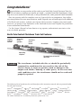
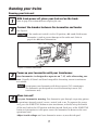
73-0020-250 12/06 North Pole Central Chrimas Train Read-to-Run Set Owner’s Manual Cauti o n—Electri c Toy Not recommended for children under eight years of age. As with all electric products, precautions should be observed during handling and use to reduce the risk of electric shock. Transformer ratings—input: 120 vac; 60 hz only. AC output: 18 v; 30 va Congratulations! C ongratulations on your purchase of the ready-to-run North Pole Central Christmas Train Set! This set features everything you need to get started—a mighty PowerMax Transformer, a huge loop of easy-to-assemble FasTrack track, a string of detailed cars, and a powerful Lionel locomotive. Have fun growing with this complete train set! Start with the set components, then follow your imagination into your own miniature world. Expand your railroad empire with additional FasTrack track sections, enhance your layout with accessories, lengthen your consist with extra cars, or operate a new locomotive at the head end of your train! Explore the possibilities at your authorized Lionel dealer. Use this Owner’s Manual to learn how to set up, operate, and maintain your train set for years of reliable operation. North Pole Central Christmas Train Set Features Lighted caboose interior Animated chase gondola Christmas music boxcar Air whistle Puffing smoke Bright headlight Operating couplers Forward-Neutral-Reverse operation Parents! The transformer included with this set should be periodically examined for conditions that may result in the risk of fire, electric shock, or injury to persons (such as damage to the output cord, blades, housing, or other parts). In the event that such conditions exist, the transformer should not be used until properly repaired. The following Lionel marks may be used throughout this instruction manual and are protected under law. All rights reserved. Lionel®, TrainMaster®, Odyssey®, RailSounds®, CrewTalk™, TowerCom™, DynaChuff™, StationSounds™, Pullmor®, ElectroCoupler™, Magne-Traction®, CAB-1® Remote Controller, PowerMaster®, Lionel ZW®, ZW®, PowerHouse®, TMCC®, Lionelville™, Lockon®, Wireless Tether™, LionMaster®, FatBoy™, American Flyer®, TrainSounds™ The name FasTrack® is used with permission from Pitsco, Inc. Table of contents Creating your layout Operating your PowerMax Transformer safely Building your Lionel layout Joining the FasTrack track sections Wiring your PowerMax Transformer Running your train Running your train set Adding smoke fluid to your locomotive’s smoke generator Coupling Operating your train Operating your Christmas music boxcar Experiencing the features of the PowerMax Transformer Reverse unit procedure PowerMax Transformer operation Powering your layout with the PowerMax Transformer Lubricating your locomotive Replacing your locomotive’s traction tire Replacing your locomotive’s headlamp Lubricating the gears on your Chase Gondola Replacing your Square Window Caboose lamp Advanced connections: powering two isolated blocks with two transformers Troubleshooting Notees Limited Warranty/Lionel Service North Pole Central Christmas Train Set Inventory • • • • • • • • • • • • • 4-4-2 Locomotive Tender with air whistle Christmas music boxcar Animated chase gondola Square window caboose PowerMax Transformer with accessory wire Three straight FasTrack track sections Eight curved FasTrack track sections One straight FasTrack terminal track section Smoke fluid Replacement traction tire Owner’s Manual Lionel RailRoader Club flyer 4 5 5 6 7 8 9 10 11 12-13 14 15 16 17 18 19 20 21 22 23 24 Creating your layout Operating your PowerMax Transformer safely Y our Lionel PowerMax Transformer is listed by Underwriter’s Laboratory Inc. and has been carefully designed to ensure peak performance. When using electrical products, basic safety precautions should be maintained. Be sure to observe the following guidelines: • Read the manual thoroughly before using this device. • This device is not recommended for children under eight years of age. • Parents should periodically inspect this product for potential hazards and, if necessary, have them repaired by an authorized Lionel Service Center. In the event that such a condition exists, the transformer should not be used until it has been properly repaired. • The PowerMax Transformer is intended to be used indoors. Do not use this device if water is present. Serious or fatal injuries may result. • Use the PowerMax Transformer only for its intended purpose. • The PowerMax Transformer was meant to operate on 120-volt, 60-Hertz power. Do not connect this product to any other power supply. • Do not operate the PowerMax Transformer with a damaged cord, plug, or case. • To avoid the risk of electrical shock, do not disassemble the unit. There are no user serviceable parts inside. If damaged, take this product to an authorized Lionel Service Center. • Do not operate the PowerMax Transformer on your layout unattended. Obstructed accessories or stalled trains may overheat, resulting in damage to your layout. • Always unplug the PowerMax Transformer from the power source when not in use. • Never insert objects into the ventilation slots on this product. Damage to sensitive electronic components can result. Creating your layout Building your Lionel layout Y our set comes with eight curved, three straight, and one terminal section of track. Figure 1 provides some examples of layouts that you can build with these track sections. By adding more FasTrack track sections, you can create an endless number of exciting track arrangements for more fun, action, and variety. The railroad empire of your dreams can quickly become a reality! Figure 1. Track layout ideas Joining the FasTrack track sections F asTrack track sections join together easily. With interlocking roadbed sections and large rail tabs, the track fits together securely so you always get good electrical contact. Take a look at Figure 2 to see how to join the track sections. 1. Line up your two sections of track. 2. Insert the rail tabs into the openings at the ends of the corresponding rails. 3. Press the sections together until the interlocking roadbed snaps into place. Rail tab Figure 2. Joining the track sections Creating your layout Wiring your PowerMax Transformer C onnect your FasTrack terminal section to the PowerMax Transformer. Use the wires that are already attached to the terminal section. Make sure that all connections are secure. Loose connections can produce extremely high temperatures. For this reason, do not touch the terminals or track connections during use. Also, do not locate scenery materials such as lichen or ground foam near the terminals. 1. Feed the wires through the notch in the FasTrack terminal section. Refer to Figure 3. 2. Loosen the red TRACK thumbscrew terminal, then slide the spadeshaped connector on the red wire into position. The thumbscrew post should be positioned between the “blades” of the spade connector. Be sure that the blades are touching the metal post. Tighten the thumbscrew to secure the connection. 3. Loosen the black TRACK thumbscrew terminal, then slide the spadeshaped connector on the black wire into position. Tighten the thumbscrew to secure the connection. Be sure that the blades are touching the metal post. Tighten the thumbscrew to secure the connection. 4. Plug the PowerMax Transformer into your wall outlet (120 volts). As your layout expands, you may also make power connections with the stripped ends of wires, placing no more than two wires on each terminal. For best performance on large layouts, it is recommended that you use 16-gauge wire to connect your PowerMax Transformer to the track. On larger layouts where several track connections are required, the use of separate junctions/terminal strips (available at your local electronics store) is recommended to prevent voltage drops. Caution! To prevent the excessive build up of heat, be sure to select the proper wire gauge for your layout. Track connections must be made with 18-gauge wire or heavier. Larger layouts require a minimum of 16-gauge wire. FasTrack terminal section Spade-shaped connector Notch Figure 3. Controller connections Running your trains Running your train set 1 With track power off, place your train set on the track. 2 Connect the drawbar between the locomotive and tender. Refer to page 8 for information on coupling the cars. See Figure 4. Caution! If the smoke unit switch is in the ON position, add smoke fluid to your locomotive’s stack to prevent damage to the smoke unit. Refer to page 8 for additional information. Figure 4. Drawbar connection 33 Power up your locomotive with your transformer. Your locomotive is designed to operate on 7-15 volts alternating current. Virtually all Lionel and Lionel-compatible alternating-current transformers are suitable. Note! Do not power your locomotive with direct-current (DC) transformers. The locomotive was designed for use with alternating-current (AC) transformers only. 4 Move ‘em out! Get your locomotive moving. Your locomotive goes through a repeating pattern of operations: forward, neutral, reverse, neutral, and so on. To sequence the reverse unit, press the DIRECTION button on your transformer, or briefly bring the throttle all the way back to the OFF position and then forward. Each press of the DIRECTION button or interruption in track power causes the locomotive to advance to the next operational state. Adjust track voltage until your locomotive moves at your desired speed. Running your train Adding smoke fluid to your locomotive’s smoke generator Y our locomotive is equipped with a smoke generator that produces safe, clean white smoke during operation if the smoke unit switch is in the ON position. Refer to Figure 8 on page 14 for the location of the switch. The smoke generator requires the periodic addition of Lionel smoke fluid in order to function. A small bottle of smoke fluid is included with this set. Press down and unscrew the cap. Pierce the end of the nozzle with a pin, then add about four drops of fluid directly into the locomotive’s stack. Smoke production commences momentarily. It will start faster if you run your locomotive at higher speeds. When smoke production decreases, add more fluid (about four drops). An idle locomotive will not smoke. Smoke production is greater at higher voltages and when the locomotive is pulling a heavy load or a long consist. Note! If you prefer to operate the locomotive without smoke or you do not want to add smoke fluid, slide the smoke unit switch to the OFF position. Caution! When the smoke unit switch is in the ON position, always keep a small amount of smoke fluid in the locomotive’s smoke generator; the generator’s element can become damaged if operated without smoke fluid. This is particularly true if your locomotive sits in neutral for an extended period of time without smoke fluid in the generator. Running your train Coupling W hen coupling your cars, at least one of the mating couplers must be open as shown at the left in Figure 5. Press down on the lock release to open the coupler, then push the cars toward each other until they lock together. Note! Keep in mind that it’s easier to couple cars on a straight stretch of track. Lock release Figure 5. Coupler operation Running your train Operating your trains with the PowerMax Transformer Y ou’re clear for departure! Move the throttle control handle forward to increase power to the track. The farther forward you push the handle, the faster your train will go. Note! Quickly shutting off or throwing the throttle all the way forward will not result in an instant change in track voltage. When operating in the conventional (non-Command) environment, remember that the greater the load on the engine (adding more cars for the engine to pull, for example), the farther forward the handle must be pushed before it will operate the locomotive. 10 Running your train Operating your Christmas music boxcar Y our Christmas music boxcar requires one nine-volt alkaline battery (not included). To install the battery, open the door, attach the battery harness to the battery, then slide the battery into the battery clip. See Figure 6. If you have a difficult time installing the battery in that confined space, simply pull away the sides of the body and lift it away. To play the Christmas music, slide the switch on the bottom of the car to the ON position. Bend the body away from the frame To play, slide the switch on the bottom of the car to ON Circuit board Speaker Battery harness Battery clip Figure 6. Battery installation and switch location 11 Running your train Experiencing the features of the PowerMax Transformer R efer to Figure 7 on page 13 for the location of the Transformer features listed in this section. THROTTLE Push the throttle forward to increase track power. The markings on the throttle approximate the percentage of full power. For more realism, push the throttle slowly to gradually increase or decrease the speed of the locomotive. Slowing or stopping the locomotive with the throttle instead of the DIRECTION button will allow you to continue in the same direction when you increase the throttle again. To achieve this effect, reduce the throttle to the point that the locomotive stops moving, don’t completely turn off the throttle. That way, your train won’t sequence into neutral. POWER-ON INDICATOR The green light will remain on during normal operation. The green light will begin to flash if you exceed the power limit of the Transformer. The unit will allow you to momentarily exceed the power limit, but power will be gradually reduced until the problem is corrected. This safety feature replaces the circuit breaker. The benefit is that the Transformer will not instantly turn off. DIRECTION The DIRECTION control button interrupts track power to activate the reverse unit in locomotives with forward-neutral-reverse operation. Note! When the DIRECTION button is presssed, track power is interrupted instantaneously. Track power is restored gradually when the DIRECTION button is released. WHISTLE/HORN The WHISTLE/HORN button will activate Lionel sound-equipped locomotives, including those equipped with the RailSounds sound system. The sound will continue until the button is released. No external sound activation buttons are needed. BELL The BELL button will activate all RailSounds bells. Press the BELL button to begin the sounds; press the button again to turn off the ringing. Note! Your locomotive is not equipped with bell sounds. Note! Do not activate horns, whistles, or bells on RailSounds-equipped locomotives until track power has been turned on for a few moments, or a continuous horn/whistle or bell sound may occur. To correct this problem, simply turn off the PowerMax Transformer, then turn it back on. Note! The PowerMax Transformer may cause random whistles in the Lionel Mighty Sounds of Steam™ tenders with a three-pin connector. We recommend that you a purchase a RailSounds-equipped tender to solve this problem. 12 Running your train Experiencing the features of the PowerMax Transformer (continued) Direction Press the DIRECTION button to go forward or reverse, or to place the locomotive in “neutral” (no movement, headlight is on). Bell Starts or stops the tolling bell in any RailSounds or TrainSounds-equipped locomotive. Press BELL to begin the sound, again to stop it. Power-on indicator The green light illuminates when the PowerMax is on. Whistle/Horn Activates the whistle or horn sound effect in your Lionel locomotives. Press WHISTLE/HORN to begin the sound; release the button to end it. Throttle Controls your locomotive’s speed. Throw the throttle forward to increase locomotive speed, backward to slow it down. Figure 7. Transformer features 13 Running your train Reverse unit procedure T OFF ON OFF ON he electronic reverse unit inside your Lionel locomotive acts like the transmission in a car. When you apply power to the track, the locomotive moves in the direction specified by the reverse unit—or it sits in neutral, awaiting another power interruption. Power interruptions are the signal that tells the reverse unit to sequence to the next operational state. To interrupt power and sequence the locomotive’s reverse unit, press the direction control button or briefly bring the throttle lever all the way back to the OFF position. Refer to Figure 9 for the location of these controls. The reverse unit alternates between three states: forward, neutral, and reverse. Also, the locomotive can be “locked” into a certain mode of operation by throwing the reverse unit switch located on the underside of the frame (see Figure 8). To lock your locomotive into a specific operational state, sequence the locomotive into the desired state and reduce track power without completely powering down the locomotive, then throw the switch to the OFF position. The DIRECTION button will then have no affect on the direction of the locomotive. If you would like to resume forwardneutral-reverse operation, simply throw the reverse unit switch back to the ON position. Additionally, this reverse unit has a “powerup reset” feature. If the locomotive sits without power for a short period of time, the reverse unit will automatically reset and start in the forward direction when the transformer is turned on or “powered up,” regardless of the reverse unit switch position. If the switch is in the OFF position, the locomotive will start in the forward direction and be “locked” Smoke unit on/ there. off switch (see Reverse unit on/ page 9) off switch Figure 8. Switch location Direction control button Whistle control button Throttle Bell control button Figure 9. Direction control button location 14 PowerMax Transformer operation Powering your layout with the PowerMax Transformer Y our PowerMax Transformer provides a total output of 1.8 amps. Also, available voltage depends on how much load is on the output. Generally, track voltage is 0-16 volts (AC). You may momentarily approach or exceed the 1.8 amp limit of the PowerMax Transformer when pulling illuminated cars, or fighting over grades with heavy loads. When you reach 1.8 amps, the green light on the Transformer will begin to flash. This indicates that the Transformer is in “fold-back mode.” In fold-back mode, the Transformer is automatically reducing, or folding back, power. This gradual reduction in power provides interruption-free power while bringing the amperage back down to a safe level. If this condition lasts for more than 30 seconds, the Transformer will shut off the power to the track and the green light will continue to flash. Move the throttle to the off position to reset the Transformer and return to normal operation. 15 Maintaining and servicing your set Lubricating your locomotive H elp your steam locomotive lead a long and productive life on your railroad by maintaining it properly. We recommend that you purchase a Lionel Lubrication and Maintenance Kit (6-62927), available from your Lionel dealer. Two basic rules to keep in mind: never over-lubricate (a small amount will do) and avoid getting grease or oil on the locomotive’s wheels, contact rollers, or your track. You’ll know your locomotive requires lubrication when visual inspection reveals dryness on the parts indicated in Figure 10. Remove accumulated dirt and dust before lubricating, and always lubricate any locomotive emerging from prolonged storage. Lubricate axle ends with Lionel oil sparingly Lubricate gears with Lionel grease sparingly Figure 10. Lubrication points 16 Lubricate axle ends with Lionel oil sparingly Maintaining and servicing your set Replacing your locomotive’s traction tire O ne of the locomotive’s drive wheels is fitted with a rubber traction tire to enhance tractive effort, allowing your locomotive to pull many cars at once. To replace the traction tire, simply unscrew the drive rod nut from the wheel using a 3/16” nut driver. Refer to Figure 11. Remove the old traction tire from under the drive rod and slip on the replacement, Lionel part no. 600-0242-206. Replace the spacer, retighten the drive rod nut, and you’re ready to pull that long freight back to the yard. Driver rod nut Spacer Lionel part no. 600-0242-206 Figure 11. Traction tire replacement 17 Maintaining and servicing your set Replacing your locomotive’s headlamp Y our locomotive lights the way with its operating headlight. During the course of normal operations, the lamp may require replacement. Refer to Figure 12 as you replace the lamp. 1. Remove the two front truck screws and carefully slide the front truck assembly off the linkage rods. 2. Lift the smoke unit out far enough from the cab to allow lamp extraction. 3. Pull the lamp straight out and replace it with Lionel part no. 600-0161-300, available from your nearest authorized Lionel Service Center or from Lionel Service. Be careful not to twist the lamp, or it may break. 4. Reinstall the smoke unit, making sure that the smoke stack lines up with the cab top opening. 5. Reassemble the front truck, making sure that the linkage rods go into the holes in the front truck. The lug wire from the smoke unit must be reinserted through the slot in the front truck assembly and secured under one of the two front screws. Tighten the screws firmly, but do not over-tighten them. Smoke unit Lionel part no. 600-0161-300 Linkage rods Smoke unit lug wire Front truck screws Figure 12. Headlight replacement 18 Maintaining and servicing your set Lubricating the gear on your Chase Gondola Y our animated gondola is equipped with a gear drive mechanism that propels the two figures around the crates in the center of the gondola when the car is moving. Occasionally, the worm gear may need lubrication. It is important to inspect the worm gear periodically. If you see little or no lubrication on the worm gear, it’s time to add a small amount of lubricant. See Figure 13. We recommend that you purchase the Lubrication and Maintenance Set (6-62927), available at your authorized Lionel Dealer. Note! If the crate load retainers become detached, make sure that they are pushed back down completely. lubricate the worm gear sparingly Figure 13. Chase Gondola worm gear lubrication 19 Maintaining and servicing your set Replacing your Square Window Caboose lamp D 1. 2. 3. 4. 5. 6. uring the course of normal operations, the lamp inside your caboose may require replacement. Follow these steps and refer to Figure 14. Lift off the roof from the window shell and body. Pull out the end frame tab from the slot formed by the caboose body and roof. The end frames are hinged at the platform to swing outward, away from the body. Remove the window shell. To remove the window shell, carefully bend the sides of the caboose outward while pulling up on the window shell until the tabs are released from the windows. Pull the lamp straight up and out of the socket. Replace it with Lionel part no. 600-8352-311, available at your authorized Lionel Service Center or Lionel Service. Lower the window shell back into the body, making sure that the tabs snap into the windows. Reposition the roof above the window shell and body, fit the tabs on the end frames into the corresponding slots in the body, and press down the roof to secure the end frame tabs. Window shell Window tab End frame tab End frame tab Part no. 600-8352-311 Hinge Figure 14. Caboose lamp replacement 20 Maintaining and servicing your set Advanced connections: powering two isolated blocks with two transformers A s you expand your layout, you may decide to create two isolated blocks of track. Trains in each block are controlled by separate transformers. Before you operate your trains on this type of layout, be sure that your transformers are in phase. Operating your trains on a layout with two transformers that are out of phase may cause damage to the locomotive’s sensitive electronic components. To be certain that your transformers are in phase, use a small 18-volt lamp with leads (available at your local electronics supply store) to perform a quick test. Refer Figure 15. Testing for proper phasing to Figure 15. 1. Attach one lamp wire to the center rail in one block. 2. Attach the second lamp wire to the center rail in the other block. 3. Power up both blocks of track. Both transformers should be set to full power. 4. See if the lamp illuminates. If the lamp illuminates brightly, your transformers are not in phase. Do not operate your trains on the layout until you change the wiring. If the lamp does not illuminate or the lamp is dim, your transformers are in phase and should not cause problems. To bring your transformers into phase, simply swap the track wires at the A and U terminals on one of the transformers. If you are using an older transformer that lacks a polarized plug, you may reverse the plug at the outlet so that the prongs are inserted into the opposite openings. Repeat the procedure described above, and you should find that the lamp does not illuminate or the lamp is dim. Note! This will also reverse the operation of the BELL and WHISTLE buttons on the transformer with the switched wires. 21 Maintaining and servicing your set Troubleshooting No lights or operation Be sure PowerMax Transformer is plugged in. Train runs, but WHISTLE, and DIRECTION buttons do not work Check track connections. The track must be connected to the “A” and “U” terminals on the Transformer. No change when DIRECTION button is pressed Be sure that your locomotive reverse unit switch is ON. Locomotive runs slowly at the far end of the track On larger layouts, additional track resistance may cause a voltage drop. Attach additional power connections to the remote portion of your track. Power wires (6-12053) are available separately. Green light begins to flash The power limit of the Transformer has been exceeded. The unit will gradually reduce power until the problem is corrected. Bell button blows whistle Switch the wire connections at the Transformer terminals. Be sure that the U post is connected to the outside rail and the A post is connected to the inside rail. Green light flashing , no power to the track The Transformer has shutdown because the power limit was exceeded for more than 30 seconds. Move the throttle to the OFF position to reset the Transformer and return to normal operation. 22 Notes 23 Limited Warranty/Lionel Service T his Lionel product, including all mechanical and electrical components, moving parts, motors and structural components, except for light bulbs, is warranted to the original consumer-purchaser, for one year against original defects in materials or workmanship when purchased through an authorized Lionel merchant. This warranty does NOT cover normal wear and tear, light bulbs, defects appearing in the course of commercial use, or damage resulting from abuse or misuse of the product by the purchaser. Transfer of this product by the original consumer-purchaser to another person voids this warranty. Modification of this product voids this warranty. Any warranted product which is defective in original materials or workmanship and is delivered by the original consumer-purchaser to Lionel L.L.C. or an authorized Lionel L.L.C. Service Center, together with proof of original purchase will, at the option of Lionel L.L.C., be repaired or replaced, without charge for parts or labor. In the event the defective product cannot be repaired, and a replacement is not available, a refund of the original purchase price will be granted. Any products on which warranty service is sought must be sent freight or postage prepaid, as transportation and shipping charges are not covered by the warranty. In no event shall Lionel L.L.C. be liable for incidental or consequential damages. Some states do not allow the exclusion or limitation of incidental or consequential damages, so the above exclusion may not apply to you. This limited warranty gives you specific legal rights, and you may have other rights which vary from state to state. Instructions for Obtaining Service If service for this Lionel L.L.C. product is required, bring the item, along with your dated sales receipt and completed warranty information to the nearest Authorized Lionel Service Center. Your nearest Lionel Service Center can be found by calling 1-800-4-Lionel, or by accessing our Website at www.lionel.com. If you prefer to send your product back to Lionel L.L.C. for repair in Michigan, you must first call 586-949-4100 or FAX 586-949-5429, or write to Customer Service, P.O. Box 748, New Baltimore, MI 48047-0748, stating what the item is, when it was purchased and what seems to be the problem. You will be sent a return authorization letter and label to ensure your merchandise will be properly handled upon receipt. Once you have received your return authorization and label, make sure that the item is packed to prevent damage during shipping and handling. We suggest that you use the product’s original packaging. This shipment must be prepaid and we recommend that it be insured. Please make sure you have followed all of the above instructions carefully before returning any merchandise for service. You may choose to have your product repaired by one of our Authorized Lionel Service Centers after its warranty has expired. A reasonable service fee will be charged. Warranty Information Please complete the information below and keep it, along with your dated sales receipt. You must present this and your dated sales receipt when requesting warranty service. Name������������������������������������������������������������������������ Address����������������������������������������������������������������������� Place of Purchase ���������������������������������������������������������������� Date of Purchase����������������������������������������������������������������� Product Number����������������������������������������������������������������� Product Description��������������������������������������������������������������� ©2006 LIONEL L.L.C., CHESTERFIELD, MI 48051-2493 UNITED STATES OF AMERICA PRINTED IN CHINA