1
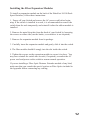
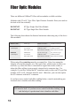
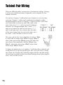
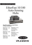
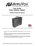
Instant EtherFast® Series EtherFast 10/100 Dual-Speed Switches Use this guide to install these Linksys products: EtherFast 10/100 12-Port Switch (DSSX12) EtherFast 10/100 16-Port Switch (DSSX16) EtherFast 10/100 24-Port Switch (DSSX24) User Guide COPYRIGHT & TRADEMARKS Copyright © 2000 Linksys, All Rights Reserved. Instant EtherFast is a registered trademark of Linksys. Microsoft, Windows, and the Windows logo are registered trademarks of Microsoft Corporation. All other trademarks and brand names are the property of their respective proprietors. LIMITED WARRANTY Linksys guarantees that every EtherFast 10/100 12-Port, 16-Port, and 24-Port Switch is free from physical defects in material and workmanship under normal use for five (5) years from the date of purchase. If the product proves defective during this warranty period, call Linksys Customer Support in order to obtain a Return Authorization number. BE SURE TO HAVE YOUR PROOF OF PURCHASE ON HAND WHEN CALLING. RETURN REQUESTS CANNOT BE PROCESSED WITHOUT PROOF OF PURCHASE. When returning a product, mark the Return Authorization number clearly on the outside of the package and include your original proof of purchase. IN NO EVENT SHALL LINKSYS LIABILITY EXCEED THE PRICE PAID FOR THE PRODUCT FROM DIRECT, INDIRECT, SPECIAL, INCIDENTAL, OR CONSEQUENTIAL DAMAGES RESULTING FROM THE USE OF THE PRODUCT, ITS ACCOMPANYING SOFTWARE, OR ITS DOCUMENTATION. Linksys makes no warranty or representation, expressed, implied, or statutory, with respect to its products or the contents or use of this documentation and all accompanying software, and specifically disclaims its quality, performance, merchantability, or fitness for any particular purpose. Linksys reserves the right to revise or update its products, software, or documentation without obligation to notify any individual or entity. Please direct all inquiries to: Linksys P.O. Box 18558, Irvine, CA 92623. FCC STATEMENT This equipment has been tested and found to comply with the limits for a Class A digital device, pursuant to Part 15 of the FCC Rules. These limits are designed to provide reasonable protection against harmful interference in a residential installation. This equipment generates, uses, and can radiate radio frequency energy and, if not installed and used according to the instructions, may cause harmful interference to radio communications. However, there is no guarantee that interference will not occur in a particular installation. If this equipment does cause harmful interference to radio or television reception, which is found by turning the equipment off and on, the user is encouraged to try to correct the interference by one or more of the following measures: Reorient or relocate the receiving antenna Increase the separation between the equipment or device Connect the equipment to an outlet other than the receivers Consult a dealer or an experienced radio/TV technician for assistance 002 Contents Introduction 2 Planning Your Network 6 Installing the Switch 8 Mounting Your Switch to a Rack 8 Connecting Nodes to the Switch 8 Powering on the Switch 9 Appendix 10 LED Displays 10 Expanding Your Switch 11 Installing Expansion Modules 12 Fiber Module Specifications and Distance Rules 13 Specifications 14 Twisted Pair Wiring 15 Customer Support 16 Introduction Congratulations on purchasing your new EtherFast 10/100 Dual-Speed Switch for your network's 10/100 migration needs. Ready to run right out of the box, the EtherFast 10/100 Dual-Speed Switch is the easiest, most flexible way to boost your network's performance with full duplex data transfer and dedicated bandwidth to each of your nodes while migrating to the power of Fast Ethernet. Unlike a standard hub that wastes network bandwidth by bouncing packets around until they finally reach their destinations, a switch forwards packets only to their intended recipients, immediately reducing network traffic congestion and improving overall efficiency for your entire network. Whether you're planning on moving to a Fast Ethernet network now or later, every Linksys EtherFast 10/100 Dual-Speed Switch is ready to go to work for you immediately. Use its switching power on your 10BaseT network to improve traffic efficiency tremendously. Connect your file server to the switch to improve access times for all of your users in one step. And when you're ready, migrate your entire network to 100BaseTX while using switching to achieve full duplex speeds of up to 200Mbps the speed is yours! Every 12, 16, and 24-Port Switch comes with a built-in expansion slot. Now you can take advantage of the biggest craze in high-speed networking technology -- fiber optics! The 100BaseFX Distance Extender Module lets you uplink to fiber backbones and send your data up to 2 kilometers -thats 2000 meters (6560 feet). Every switch packs a full suite of error detection and correction features for reliable communication every time. Auto partitioning, data collision control, and incoming frame retiming ensure that not a single bit of data is lost, even during the heaviest moments of network traffic. Built to last, your new switch is optimized to deliver high-end video, multimedia, database, and other speed-intensive applications at blazing speeds. 2 About Fast Ethernet As the demand for desktop video, multimedia development, imaging, and other speed-intensive applications continues to rise, the need for high performance, fault tolerant LAN technology will become more critical. Standard Ethernet, which has been the most popular networking technology to date with a maximum data throughput of 10 Mbps, is becoming insufficient to handle the latest video, multimedia, and other speed-intensive client/server LAN applications. Among the proposed solutions to the dilemma of network speed, Fast Ethernet has emerged as the most viable and economical. Capable of sending and receiving data at 100 Mbps (megabits per second), it is more than fast enough to handle even the most demanding video and other real-time applications. Although there are a number of different competing Fast Ethernet implementations, 100BaseTX is by far the most popular. Operating on two pairs of Category 5 unshielded twisted-pair (UTP) cabling, 100BaseTX supports high speed signaling and is relatively inexpensive. Because it uses four wires for data transmission and the same packet format, packet length, error control, and management information as 10BaseT, 100BaseTX can be made to communicate with older 10BaseT equipment when routed through a switch. This scalability is one of 100BaseTX's major advantages over other forms of Fast Ethernet: it allows critical, speed-dependent network segments to be upgraded to 100BaseTX speeds as needed without rewiring, refitting, and retraining an entire site. Heterogeneous networks can now mix both slow and fast network segments for different users or for different departments. Publishing, R&D, video, multimedia, or accounting departments can enjoy a 100Mbps pace, while other corporate segments can operate at slower and more economic 10Mbps speeds. A network without a switch is often called a shared-bandwidth network because the net's overall bandwidth is shared among all of the nodes each PC, file server, or other node gets a piece of the bandwidth. In a shared network, data packets are sent to all available nodes until they fall upon their destination. Much of the bandwidth, consequently, is wasted because some packets have to spend time "looking" for their destinations. 3 Switched Ethernet, by contrast, is closer to the notion of individual telephone lines: a switching hub examines the incoming MAC addresses of network packets and forwards them directly to their destinations without repetition, reducing bandwidth waste and resulting in more predictable network performance. Each node receives its own full-speed pipeline -- bandwidth isn't divided up. Switched Ethernet can improve data transfer speeds and overall efficiency for 10BaseT networks, 100Mbps networks, or both. The Advantages of Switching The two main advantages of using a switch like the 10/100 Dual-Speed Switch are migration and performance boosts. 100BaseTX and 10BaseT networks are not automatically compatible with each other. Because of their different speeds, their hardware is not readily interchangable a 10BaseT network adapter, for example, cannot be connected directly to a 100BaseTX network segment. By using a switch, 10BaseT and 100BaseTX hardware can be made to communicate with each other so you don't need to discard your slower 10Mbps network hardware as you migrate to Fast Ethernet. As for performance, switching technology boosts any network's efficiency right away. A network without a switch is called a shared network, which means that the network's total bandwidth is equal to its speed divided by the number of users who are actively using the net. A switched network, by contrast, gives each user a full-speed pipeline that isn't shared by any other users, which causes an immediate speed and/or efficiency increase of up to 80%. 4 Here are some scenarios in which a switch can be applied: · Speeding up a 10BaseT Network On a 10BaseT network, you might connect users to one of the switch's 10/100 ports and the file server to the other, allowing the server to service more users faster because it enjoys its own switched pipeline into the network. · Mixing 10BaseT with 100BaseTX 10BaseT and 100BaseTX hardware not readily compatible with each other. With a switch you can create 10Mbps network segments for servicing users that don't need tremendous speed, and 100Mbps segments for users who depend on graphics, video, multimedia, database, or other speedy applications. · Adding 10Mbps Network Peripherals In addition, since 100BaseTX is a relatively new standard, there aren't as many network peripherals available for it as there are for 10BaseT. Most network modems, print servers, sniffers, and other network peripherals are made to operate at a speed of 10Mbps, making them incompatible with 100Mbps networks unless you have a switch. A switch can add 10Mbps hardware to your network wherever you want it. 5 Planning Your Network The rules that govern how switches are distributed in Fast Ethernet are slightly different from 10BaseT networking rules. Cabling specifications, distance limits, and other topology rules must be followed in order to avoid network collisions and data loss. Here are the most important rules to follow: · 100BaseTX requires four-pair, Category 5 UTP (EIA 568, Cat 5)cabling. · The maximum cable length from a node to a repeater, switch, or hub is 100 meters (328 feet). · The maximum length for a Category 5 100BaseTX cable between a workstation and a stackable or other shared bandwidth hub is 100 meters (328 feet). · A single or stacked 100Mbps hub is counted as one repeater in Fast Ethernet rules; a 10/100 switch or 10BaseT hub is not counted as a repeater. · You can install as many switches as you want on the same network, given you don't position the switches more than 100 meters (328 feet) apart. · The maximum distance between 2 100Mbps hubs without a switch connected in between is 5 meters (16.4 feet). 6 The diagram below shows one possible configuration of a 12-Port Switch in a Fast Ethernet environment; if you have an 16 or 24-Port Switch, the configuration remains the same. Note that like all Fast Ethernet network hardware, the switch requires Category 5 UTP network cabling, which is available at most computer stores. In this example, each workstation has access to all of the resources on the network -- 10Mbps users can access the 100Mbps stations, and vice-versa. While allowing the 10Mbps and 100Mbps segments to communicate, the switch helps optimize traffic by adding switching to the network, which can improve performance by up to 80% (even on the slower 10Mbps segment). Notice that the servers are both connected directly to the switch. This improves server access times for all users. Web Server File Server DSSX12 10Mbps Segment 100Mbps Segment 7 Installing the Switch Package Contents Carefully remove the switch from its packaging. Make sure that you received all of the items listed below. If any items are missing or damaged, contact your Linksys dealer for replacement part(s). · EtherFast 10/100 Dual-Speed, Autosensing 12, 16 or 24-Port Switch · Rack Mounting Hardware · AC Power Cord · User Guide and Registration Card Rack Mounting Your Switch Every 12-Port, 16-Port and 24-Port Switch is equipped with mounting holes that can be used to secure it in a stationary or movable rack. After screwing a mounting bracket into each side of the switch, lift the switch into your rack and secure the brackets in place with additional screws. Connecting Nodes to the Switch The front of the 12-Port Switch has twelve RJ-45 ports the 24-Port Switch has twenty-four. Each switch also has an uplink port (shared with the port 12 on the 12-Port model and port 16 on all other switches). Each port automatically detects the speed, type, and duplex of the cabling attached to it, and can operate in either half or full duplex, giving possible speeds of 200Mbps, 100Mbps, 20Mbps, or 10Mbps. 8 Each switch can be connected to workstations, PCs, file servers, hubs, repeaters, bridges, or other switches. Each cable connected to the switch must be a Category 5 UTP network cable with RJ-45 tips, and should not exceed 100 meters (328 feet), in length. Ready-to use network cables of various lengths can be purchased at most computer stores. See page 15 for more details. Connecting Workstations and PCs Workstations and PCs should be connected to the switch with straight-through Category 5 network cabling. If connecting a computer directly to one of the switch's ports, connect one end of the cable into the switch, then plug the other end of the cable into the computer's 10Mbps or 100Mbps network adapter. Uplinking- Connecting to Other Switches and Hubs Each 10/100 Dual-Speed Switch has a shared uplink port -- which sits right next to port 12 or 16 on the switch (depending on the model you have) for connecting or cascading the switch to other devices. This uplink port is shared, meaning that when it is in use, the port next to it on the switch cn no longer be used. Since the uplink port crosses the polarity of your cabling for you, there is no need to use any special cables. A regular, straight-through Cat 5 RJ-45 Fast Ethernet cable will do. Connect one end of the cable to the switch, then connect the other end to any standard RJ-45 port on your hub or other device. Powering On the Switch Plug in the switch's AC power cord. When the switch is first powered up, it will put itself into a Diagnostic/Self-check mode, which should only take a few moments, and the Power LED will light up. As your network cables are connected to the switch, each port's corresponding Link/Activity, Speed (10 or 100) and Full Duplex LEDs will light up. When data is transmitted or received, the Link/Activity (LK/ACT) LEDs will or flicker. Finally, the Full Duplex/Collision (FDX/COL) LED will flicker or change color as data collisions on the network are detected and corrected. If the switch experiences excessive data collisions, verify that your network cabling is securely crimped and installed correctly. 9 Appendix LED Displays Power ON when unit is powered on Link/Activity ON when a link has been established, flickering when activity on the port is detected Full Duplex/Collision ON when port is operating at full duplex, changing color or flickering when collision is detected 100/10 ON when port is running at 100Mbps (LK/ACT) (FDX/COL) 10 Expanding Your 10/100 Dual-Speed Switches The EtherFast 12, 16 and 24-Port Switches are equipped with an expansion slot in the back of the switch into which expansion modules with different features can be inserted. The 100BaseFX Fiber Optic Distance Extender Module allows you to connect your EtherFast 10/100 Dual-Speed Switch to other switches, hubs, routers, or high-speed network backbones using fiber optic cabling. The 100BaseFX Fiber modules have either an ST or SC-Type connector for use with high-bandwidth multi-mode fiber optic cabling. Fiber cable is capable of carrying data up to 2000 meters (about 6560 feet) without requiring any signal boosting. The modules, model numbers: DSSXFXST (ST-Type) and DSSXFXSC (SC-Type) are available through your Linksys dealer. If you are installing a Fiber Optic Distance Extender module of any kind, make sure that you consult the special section on Fiber Optics in the Appendix before connecting any cabling. 11 Installing the Fiber Expansion Modules To install an expansion module on the back of the EtherFast 10/100 DualSpeed Switches, follow these instructions: 1. Power off your Switch and remove the AC power cord before beginning. If the switch is installed in a rack, it is recommended to remove the switch from the rack temporarily and reinstall it after the add-on module is installed. 2. Remove the metal faceplate from the back of your Switch by loosening the screws on either side (use the knobs, a screwdriver is not required). 3. Remove the expansion module from its package. 3. Carefully insert the expansion module and gently slide it into the switch. 4. The fiber module should fit snugly into the slot inside the switch. 5. Tighten the screws on the expansion module to secure it in place. You may now reinstall the switch into its rack (if required), reconnect the AC power cord and power on the switch to resume normal operation. If you are installing a Fiber Optic Distance Extender module of any kind, make sure that you consult the special section on Fiber Optics included in the Appendix before connecting any cabling. 12 Fiber Optic Modules There are different 100BaseTX fiber add on modules available switches: Modules with ST or SC-Type Fiber Optic Distance Extender Ports (can used on the back of all the switches): DSSXFXST DSSXFXSC ST-Type Single-Port Fiber Module SC-Type Single-Port Fiber Module The following chart shows the distance limitations when using any of the above fiber modules: Distance (m/ft) Cable Type Module in Switch A Module in Switch B 412/1330 (Half Duplex) Multi-Mode 62.5/125uM Fiber Optic Cable Any ST or SC-Type Any ST or SC-Type 100BaseFX Fiber 100BaseFX Fiber Optic Distance Extender Optic Distance Extender 2000/6560 (Full Duplex) Multi-Mode 62.5/125uM Fiber Optic Cable Any ST or SC-Type Any ST or SC-Type 100BaseFX Fiber 100BaseFX Fiber Optic Distance Extender Optic Distance Extender When using fiber, noise loss must be accounted for. Noise loss means the integrity of your data transfer over fiber optic lines, which occurs in fiber connections, e.g. where the fiber is converted to copper lines in the switch, or where the fiber cabling is not properly crimped on its connector tips. For example, if your fiber cabling has ST connectors and you have an SC-type fiber module, an SC to ST converter must be used. Otherwise, you can also replace the ST connector with an SC connector. If you have never worked with fiber cabling before, consult a networking professional who is familiar with fiber cabling. NOTE: Changing connectors must be done professionally, and proper tools must be used. If you have never worked with fiber cabling, consult the help of a professional who is familiar with fiber. 13 Specifications Standards IEEE 802.3 and IEEE 802.3u Protocol CSMA/CD Ports 12, 16 or 24 10BaseT/100BaseTX Dual-Speed Autosensing RJ-45 Ports, One Shared Uplink Port Speed per Port 10Mbps or 100Mbps (Half Duplex) 20Mbps or 200Mbps (Full Duplex) Duplex Modes Half or Full Duplex, per port MAC Addresses Unicast Entries: 16,384 Addresses Multicast Broadcast Addresses: Unlimited Addresses Max Frame Size 1536 Bytes Buffer Memory 64K Per Port Cabling Type 10BaseT/100BaseTX Category 5 UTP or Better LED Indicators Power, Full Duplex/Collision per port, Link/Activity per port, 100/10 per port Dimensions 17.3 x 9.8 x 2.6 Weight 6.6 to 7.7 lbs. AC Power 90-250V AC, 50-60Hz Power Consumption 35-40 Watts Certifcations FCC Class A, CE Mark Commercial 14 Twisted-Pair Wiring There are different grades, or categories, of twisted-pair cabling. Category 5 is the most reliable and widely compatible, and is required for Fast Ethernet networks. You can buy Category 5 cabling that is pre-crimped, or you can crimp your own. Category 5 cables can be purchased or crimped as either straight-through or crossed. A Category 5 cable has 8 thin, color-coded wires inside that run from one end of the cable to the other. Only wires 1, 2, 3, and 6 are used by Ethernet networks. In a straight-through cable, wires 1, 2, 3, and 6 at one end of the cable are also wires 1, 2, 3, and 6 at the other end. In a crossed cable, the order of the wires change from one end to the other: wire 1 be-comes 3, and 2 becomes 6 and vice versa. The color code for the 4 wires should be as follows: Wire 1, white with an orange stripe; Wire 2, orange; Wire 3, white with a green stripe; Wire 6, green. The other four wires have to be connected as follows: Wire 4, blue; Wire 5, white with a blue stripe; Wire7, white with a brown stripe, Wire 8, brown. To figure out which wire is wire number 1, hold the cable so that the end of the plastic RJ-45 tip (the part that goes into a wall jack first) is facing away from you. Flip the clip so that the copper side faces up (the springy clip will now be parallel to the floor).When looking down on the coppers, wire 1 will be on the far left. 15 Customer Support For help with the installation or operation of your EtherFast 10/100 12Port, 16-Port or 24-Port Dual-Speed Switch, contact Linksys Customer Support at one of the phone numbers or Internet addresses below. Customer Support Fax Email Website FTP Site (800) 326-7114 (949) 261-1288 (949) 261-8868 [email protected] http://www.linksys.com ftp.linksys.com 16 Notes http:/ / ww w.linksys.c om Copyright 2000 Linksys, All Rights Reserved. Printed in the U.S.A.