1
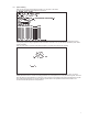
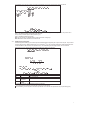
Eight (8)-Port Gigabit Ethernet Switch
USER'S GUIDE
Eight (8)-Port 1000BASE-T/100BASE-TX/10BASE-T Gigabit Ethernet Switch
LINDY Part No. 25008
TABLE OF CONTENTS
1
UNPACKING INFORMATION ................................................. 3
2
PRODUCT INTRODUCTION .................................................. 4
2.1
Models ..................................................................................... 4
2.2
Key Features............................................................................ 4
2.3
The Front Panel ....................................................................... 4
2.3.1
1000BASE-T.................................................................... 4
2.3.2
Cabling ............................................................................ 4
2.3.3
Status LEDs ..................................................................... 5
2.4
3
2.4.1
Power Socket................................................................... 5
2.4.2
Network Ports .................................................................. 5
2.4.3
Console Port .................................................................... 5
INSTALLATION...................................................................... 6
3.1
4
The Rear Panel ........................................................................ 5
Rackmount placement .............................................................. 6
HELPFUL SUGGESTIONS .................................................... 7
4.1
Prior to Installation.................................................................... 7
4.2
Half- and Full-Duplex................................................................ 7
4.3
Auto-Negotiation....................................................................... 7
4.4
MAC Address Table .................................................................. 7
5
SAMPLE APPLICATION ........................................................ 8
6
SMART FUNCTION CONFIGURATION.................................. 9
7
8
6.1
HyperTerminal.......................................................................... 9
6.2
System Initiating..................................................................... 10
USE FUNCTION MENU........................................................ 11
7.1
Main menu ..............................................................................11
7.2
System Configuration ..............................................................11
7.3
Port Configuration .................................................................. 12
7.4
Port Trunking Configuration .................................................... 13
7.5
Port Mirroring Configuration .................................................... 14
7.6
VLAN Configuration................................................................ 15
7.7
Priority Configuration .............................................................. 16
7.8
Port Statistics ......................................................................... 16
7.9
Restart ................................................................................... 17
7.10
Exit ........................................................................................ 17
PRODUCT SPECIFICATIONS.............................................. 18
2
1
UNPACKING INFORMATION
Thank you for purchasing this Switch. Before continuing, please check the contents of the product package. This product
package should contain the following items:
One (1) Gigabit Ethernet Switch.
One (1) Power Cord.
One (1) Four (4) Rubber Feet.
One (1) Rackmount Kit.
One (1) Console Cable
This User’s Guide.
If anything is missing, please contact your place of purchase immediately.
ƍ
ƍ
ƍ
ƍ
ƍ
ƍ
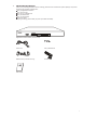
Gigabit Ethernet Smart Switch (19 inches case)
Power Cord
Four (4) Rubber Feet
Rackmount Kit (19 inches case only)
Console cable
User’s Guide
3
2
PRODUCT INTRODUCTION
2.1
Models
The switch provides Eight (8) Gigabit copper ports. Each port is equipped with 2000 Mbps, Full-Duplex, Collision Free
Bandwidth. It’s a multi-speed, versatile network device that combines Gigabit, Fast Ethernet, and Ethernet ports in a single
device.
2.2
ƍOperates at maximum packet forwarding rate in 14880pps/10M, 148800pps/100M and 1488000pps/1000M.
ƍSupports 16K MAC address entries.
ƍProvides 1.5M bytes Packet Memory Buffer.
ƍProvides Flow-Control mechanism to ensure zero packet loss. They are IEEE802.3x for Full-Duplex operation and
Back-Pressure for Half-Duplex operation.
ƍProvides Store-and-Forward forwarding scheme.
ƍProvides 1 DB9 RS-232C console interface configured as DTE for operation, diagnostics, status, and configuration
information.
ƍProvides Menu-Driven console interface from the console port by VT-100 compatible terminal.
ƍProvides Port-Mirroring function on port 8.
ƍProvides Link Aggregation function (2,3 or 4 ports per link).
ƍSupports up to 4 Trunk groups.
ƍSupports IEEE 802.3ac frame extension for VLAN Tagging.
ƍSupports Tag-Based VLAN as in IEEE 802.1Q.
ƍSupports up to 32 Port-Based VLANs.
ƍProvides 4-level priority for switching.
ƍSupports 19Gbps backbone bandwidth.
2.3
The Front Panel
Key Features
Gigabit Ethernet Switch (19 inches case)
2.3.1 1000BASE-T
The switch is primarily used for network backbone connections.
For the 1000BASE-T TP port, it provides an Auto-Negotiation function that senses for the attached device's maximum
operating speed and automatically sets the Switch to operate at that speed. Users only need to connect a network cable into
any TP port, and the Auto-Negotiation function will do the rest.
2.3.2 Cabling
1000Mbps - To transmit at 1000Mbps requires Category 5 TP cabling that must use all Four (4) pairs twisted-pair wire for
RJ-45 connector.
100Mbps - To transmit at 100Mbps requires Category 5 TP cabling.
10Mbps - When transmitting at 10Mbps Category 3, 4 or 5 TP cabling with RJ-45 sockets can be used.
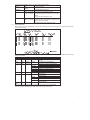
Port Type
Cable Type
Connector
1000BASE-T Cat.5 TP
RJ-45
100BASE-TX Cat.5 TP
RJ-45
10BASE-T
Category 3, 4 or 5 TP RJ-45
Note: Category 5 TP cable recommended whenever installing new cabling.
To transmit at 1000Mbps requires Category 5 TP cable using Four (4) pairs Twisted-Pair wire.
4
2.3.3 Status LEDs
The Switch comes with
function.
Name
Color
Power
Green
Off
Link/Act
Green
Blink
Off
1000M
Green
Off
10M/100M Green
Off
Full
Green
Collision Blinking
Half
Off
2.4
a complete range of LEDs. The table below lists each LEDs name, color and a brief description of its
Function
Power on, normal operation
Power off
Link On
Activity
Link Off
1000M Speed
Not 1000M Speed
100M Speed
10M speed
Full-duplex mode
Collision
Half-duplex mode
The Rear Panel
Gigabit Ethernet Switch (19 inches case)
2.4.1 Power Socket
The Power Socket is designed to be used with the power cord included in the product package.
Attach the female end of the power cord to the male power connector on the back panel.
Attach the male end of the power cord to a grounded power outlet.
ƍ
ƍ
2.4.2 Network Ports
The Switch provides Eight (8) 10BASE-T/100BASE-TX/1000BASE-T (RJ-45 connector) ports.
2.4.3 Console Port
The console port interface conforms to the RS-232 electrical specification. This interface supports asynchronous data of Eight
(8) data bits, One (1) stop bit, and no parity bit. The unit only operates at 38400bps rates with RS-232 cable in system
configure.
5
3
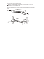
INSTALLATION
To locate the switch on a rackmount: (19 inches case only)
Attach the Four (4) rubber feet included in the product package to the bottom of the Switch, one in each corner.
Place the Switch on a rackmount.
Plug in all network connections and the power cord
ƍ
ƍ
ƍ
3.1
Rackmount placement
Attach One (1) rackmounting bracket on each side of the Switch front panel and secure each bracket with the provided
screws.
Use the other provided screws to secure each Switch to the rack.
6
4
HELPFUL SUGGESTIONS
4.1
Prior to Installation
Before installing the Switch and connecting network devices, it is important to plan the network's layout. Things you should
consider include:
Dedicated Bandwidth: File servers and other high-traffic hardware improve their performance if they have their own
dedicated 10Mbps, 100Mbps, or 1000Mbps bandwidth.
Full-Duplex: Determine which devices support Full-Duplex connections.
Fast Ethernet & Gigabit Ethernet: Make sure rules for cable lengths and categories are followed. 100BASE-TX and
1000BASE-T have the same rules for cable and distance.
Auto-Negotiation: Devices with different speeds may be easily swapped when the other end of the cable is fixed to a port
with Auto-Negotiation.
ƍ
ƍ
ƍ
ƍ
4.2
Half- and Full-Duplex
The Switch supports both Half- and Full-Duplex modes for 10BASE-T and 100BASE-TX. But the 1000BASE-T only supports
Full-Duplex mode.
In Half-Duplex mode: Data cannot be transmitted and received at the same time. Attached devices must finish transmitting
data before they can receive data.
In Full-Duplex mode: Data can be transmitted and received at the same time.
However:
Full-Duplex transmission is only possible between two devices with a dedicated link (e.g., Switch-Switch, Switch-PC)
Both devices must have Full-Duplex capability
Both devices must be set to Full-Duplex (e.g. Auto-Negotiation – Auto-Negotiation, Non-Auto-Negotiation to
Non-Auto-Negotiation)
The 100BASE-TX/10BASE-T or 1000BASE-T/100BASE-TX/10BASE-T ports on the Switch detect and set the line's operating
mode by using their Auto-Negotiation function.
ƍ
ƍ
ƍ
ƍ
ƍ
4.3
Auto-Negotiation
Every 1000/100/10Mbps speed port on these Switches has a built-in "Auto-Negotiation" function. This technology
automatically sets the best possible bandwidth as soon as a connection is established with another network device (usually at
Power “On” or Reset). This is capability is achieved via the Switch’s Auto-Negotiation function that automatically detects the
modes and speeds the second (attached) device is capable of.
Evaluating Auto-Negotiation Capability:
if attached device is: the Switch will automatically set its TP ports to operate at:
1000Mbps
2000Mbps (1000BASE-T, Full-Duplex)
with Auto-Negotiation Note: Almost all 1000Mbps devices only operate in Full-Duplex mode.
100Mbps
100Mbps (100BASE-TX, Half-Duplex)
no Auto-Negotiation
100Mbps
200Mbps (100BASE-TX, Full-Duplex)
with Auto-Negotiation
10Mbps
10Mbps (10BASE-T, Half-Duplex)
no Auto-Negotiation
10Mbps
20Mbps (10BASE-T, Full-Duplex)
with Auto-Negotiation
Note: If the attached device is set to a fixed mode (ex: Forced Full-Duplex) it will not operate as an Auto-Negotiation device.
4.4
MAC Address Table
Every Ethernet data packet includes both source and destination addresses. This Six (6) bytes ID is called the MAC (Media
Access Control) Address. It supports 16 K MAC address.
The model can automatically learn and store MAC addresses. However, the MAC address table is volatile: it disappears when
the Switch is powered “Off” or reset.
Note: When the network needs reconfiguration, we recommend to restart the Switch first. After all nodes have been moved,
Remove the power cord and re-attach it to rebuild the internal MAC address table.
7
5
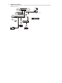
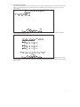
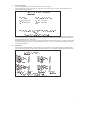
SAMPLE APPLICATION
The application for these Switches is as a "big pipe" backbone interconnecting file servers with bandwidth-hungry workgroups,
departments, and offices.
Serve r with Gig a bit Ethe rnet Ad a p ter
2000Mbps
Full-Duplex
100m max.
24 10/100 p o rts with 2 Gig a b it p orts switc h
24-Port + 2 Giga Port Switch
200Mbps
Full-Duplex
100m max.
Worksta tio ns wit h 10 /10 0
Fast Ethe rne t Ad ap te rs
Printer Se rver
Printer
Wo rksta tio ns with 10/100
Fa st Ethernet Ad a p te rs
8
6
SMART FUNCTION CONFIGURATION
6.1
HyperTerminal
The Switch has a smart function that you can use to manage your local area network (LAN) more effectively. You can also use
the default setting to operate the Switch as a dumb switch.
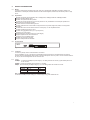
If you want to use smart function, install the Switch as below:
Use the “RS-232” connector to connect the Switch to a computer. Connect One (1) cable end to the Switch, and connect the
other end to the computer’s “COM1” or “COM2” port.
Note: If your Windows program doesn’t have a hyper terminal, you have to install it first.
Power “ON” the Switch
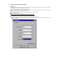
Execute the “HyperTerminal” program:
Start Menu ! Application Program ! Communication ! Hyper Terminal
Setup the connection content of Hyper Terminal:
In connection tag, select which “COM” port is used to connect PC and the Switch.
Then press the “SETUP” button, set “Bits per second” to 38400, “Data bits” to 8, “Parity” to None, “Stop bits” to 1, “Flow
control” to None.
ƍ
ƍ
ƍ
ƍ
ƍ
ƍ
9
6.2
System Initiating
After you have set up the “HyperTerminal” program, you can power on the switch.
You will see the initializing process appears on the screen.
Hjhbcju!Fuifsofu!Tnbsu!Txjudi!
Qpxfs.vq!Tztufn!Tfmg.ejbhoptujd!Qspdftt!
W2/11!13.36.3113!)d*!Dpqzsjhiu!3113/!
!
Dpotpmf!J0P!uftu!///!
!!"#$%&'()*+,-./0123456789:;<=>?@ABCDEFGHIJKLMNOPQRSTUVWXYZ[\]^_`a!
!!bcdefghijklmnopqrstuvwxyz{|}~!
!
SBN!uftu!///////////QBTT!
FFQSPN!uftu!////////QBTT!
FF!joufsgbdf!uftu!Qbtt"!
NJJ!uftu!Tvddftt!
NBJOCPBSE!DPN!!!SBNCJTU!UFTU!///////QBTT"!
NBJOCPBSE!BMF!!!SBNCJTU!UFTU!///////QBTT"!
NBJOCPBSE!TDN!!!SBNCJTU!UFTU!///////QBTT"!
NBJOCPBSE!HQD2!!SBNCJTU!UFTU!///////QBTT"!
NBJOCPBSE!HQD3!!SBNCJTU!UFTU!///////QBTT"!
NBJOCPBSE!HQD4!!SBNCJTU!UFTU!///////QBTT"!
NBJOCPBSE!HQD5!!SBNCJTU!UFTU!///////QBTT"!
NBJOCPBSE!HQD6!!SBNCJTU!UFTU!///////QBTT"!
NBJOCPBSE!HQD7!!SBNCJTU!UFTU!///////QBTT"!
NBJOCPBSE!HQD8!!SBNCJTU!UFTU!///////QBTT"!
NBJOCPBSE!HQD9!!SBNCJTU!UFTU!///////QBTT"!
Qsftt!=Foufs?!up!foufs!uif!vtfs!joufsgbdf!qsphsbn/!
Here we can see messages shown in this power-on screen. As described in the screen, this is a Self-Diagnostic process
running during power-on stage. Regardless of the test result is successful or not, you are always requested to press <Enter>
to enter next stage.
After you press <Enter> to enter the user interface program, you will see the screen shown as follow:
!
!
!
!
!!!!!!!!!!!!!!!!!!!!!!!!!!!!!!!!!!Tnbsu!Txjudi!
!
!!!!!!!!!!!!!!!!!!!!!!!!!!!!!!!!!Vtfs!Joufsgbdf!
!
!!!!!!!!!!!!!!!!!!!!!!!!!!!!!w2/11!)d*!Dpqzsjhiu!3113!
!
!
!
!
!
!
!!!!!!!!!!!!!!!!!!!!!!!!Qbttxpse!;!
!
!
!
!
!
!
Log-in is required to access the command console. A password is used to provide the basic security control. The factory
default password is “admin”. The user can change password once in the System menu. If the password is forgotten, user must
return this device for SW maintenance. In this log-in screen, input the correct password and press enter will lead user to main
menu. Without valid password, user cannot monitor the system status or set special functions from this interface. We
recommend users take special care of the password.
10
7
USE FUNCTION MENU
7.1
Main menu
The main menu is the top level of all menu-driven screens. All functions are selected from this screen.
The main menu function selections are listed below:
1. System Configuration
2. Port Configuration
3. Port Trunking Configuration
4. Port Mirroring Configuration
5. VLAN Configuration
6. Priority Configuration
7. Port Statistics
8. Restart
9. Exit
!
!
!!!!!!!!!!!!!!!!!!!!!!!!!!!!!!!Nbjo!Nfov!
!!!!!!!!!!!!!!!!!!!!!!!!!!!!!!!>>>>>>>>>!
!!!!!!!!!!!!!!!!!!!!!!!!!!!Tztufn!Dpogjhvsbujpo!///!
!
!!!!!!!!!!!!!!!!!!!!!!!!!!!Qpsu!Dpogjhvsbujpo!///!
!
!!!!!!!!!!!!!!!!!!!!!!!!!!!Qpsu!Usvoljoh!Dpogjhvsbujpo!///!
!
!!!!!!!!!!!!!!!!!!!!!!!!!!!Qpsu!Njsspsjoh!Dpogjhvsbujpo!///!
!
!!!!!!!!!!!!!!!!!!!!!!!!!!!WMBO!Dpogjhvsbujpo!///!
!
!!!!!!!!!!!!!!!!!!!!!!!!!!!Qsjpsjuz!Dpogjhvsbujpo!///!
!
!!!!!!!!!!!!!!!!!!!!!!!!!!!Qpsu!Tubujtujd!///!
!
!!!!!!!!!!!!!!!!!!!!!!!!!!!Sftubsu!///!
!
!!!!!!!!!!!!!!!!!!!!!!!!!!!Fyju!
!
!!!!!!!!!!!!!!!!!!!!!!!!!!!!Dpogjhvsf!uif!qbttxpse/!
!!!!!!!!!!!!!!!!!!Vtf!bsspx!lfzt!up!npwf/!=Foufs?!up!dpogjsn/!
You can press the number key (on the right hand side of the keyboard) 8 for moving up the menu bar and 2 for moving down.
When the menu bar stops on the right item that you want to execute, press “Enter” to go into the sub-menu.
Note: Before using number key for moving up or down, please make sure the “Num Lock” LED should not be lit.
There are 4 types of arrow indicator messages which are listed below:
Item
Explanation
[8]:Up
Press the number key 8 to move UP your menu bar.
[2]:Down
Press the number key 2 to move DOWN your menu bar.
[6]:Right
Press the number key 6 to move RIGHT your menu bar.
[4]:Left
Press the number key 4 to move LEFT your menu bar.
[Enter]:Execute
Press Enter to EXECUTE the sub-menu.
[Space]:Option
Press Spacebar to change the current setting to next option.
[ESC]=Exit
Press ESC to EXIT the sub-menu.
7.2
System Configuration
If we want to enable aging time of the system, select ” System configuration” sub-menu and press “Enter” to execute. We’ll see
the following menu on the screen.
!
!!!!!!!!!!!!!!!!!!!!!!!!Tnbsu!Txjudi!;!Tztufn!Dpogjhvsbujpo!
!!!!!!!!!!!!!!!!!!!!!!!!>>>>>>>>>>>>>!
!
!
!
!
!
!
!!!!!!!!!!!!!!!!!!!!!!!Qbttxpse!!!!!!!!!!;benjo!
!
!!!!!!!!!!!!!!!!!!!!!!!Bhjoh!ujnf!!!!!!!!;411!!!!!!!!!!!)tfdpoet*!
!
!!!!!!!!!!!!!!!!!!!!!!!Mphpvu!ujnf!!!!!!!;1!!!!!!!!!!!!!)njovuft*!
!
!!!!!!!!!!!!!!!!!!!!!!!Bvup!sfgsfti!ujnf!;23!!!!!!!!!!!!)tfdpoet*!
!
!
!
!
!!!!!!!!!!!!!!!!!!!!!!!!!!!!!!!!!!=!Sfuvso!?!
!!!!!!!!!!!!!!!!!!Qbttxpse!pg!uif!benjojtusbups/!!!!!!!!!!!!!!!!!!}!SFBE0XSJUF!
!!!!!!!!!!!!!!!Vtf!bsspx!lfzt!up!npwf/!=Foufs?!up!nblf!dibohft/!
11
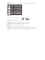
In the “System Configuration” menu, you can setup the following settings.
Item
default
explanation
Password
admin
The login password.
(A string)
Aging time
300
Forwarding table aging period
(Integer, in seconds) Aging Time value is between 0~65000.
Logout time
0
Set the automatic logout time. The console will be
(Integer, in minutes) automatically logged out if idle time period over this
setting.
Logout Time value is between 0~255.
Auto refresh time 12
Many console screens contain data that can be
(Integer, in seconds) updated constantly. This parameter controls the time
between each screen update.
Auto Refresh Time value is between 0~255.
7.3
Port Configuration
When you go into the “Port Configuration” sub-menu, the current state will be scanned for all 8 ports of the Switch and shown
on the screen as follow:
!
!!!!!!!!!!!!!!!!!Tnbsu!Txjudi;!Qpsu!Dpogjhvsbujpo!
!!!!!!!!!!!!!!!!!>>>>>>>>>>>>!
!
!Qpsu!!Mjol!!!!!Benjo!!!!!Uzqf!!!!!!!!Dvssfou!!!!!!Gmpx!!!!!!!!!Gmpx!Dpouspm!
!!!!!!!Tubuvt!!!Tubuvt!!!!Dpogjh!!!!!!Uzqf!!!!!!!!!Dpouspm!!!!!!Tubuvt!
!......................................................................!
!12/!!!Pgg!!!!!!Fobcmfe!!!Bvup.Ofhp!!!21IEY!!!!!!!!Pgg!!!!!!!!!!Pgg!
!13/!!!Pgg!!!!!!Fobcmfe!!!Bvup.Ofhp!!!21IEY!!!!!!!!Pgg!!!!!!!!!!Pgg!
!14/!!!Pgg!!!!!!Fobcmfe!!!Bvup.Ofhp!!!21IEY!!!!!!!!Pgg!!!!!!!!!!Pgg!
!15/!!!Pgg!!!!!!Fobcmfe!!!Bvup.Ofhp!!!21IEY!!!!!!!!Pgg!!!!!!!!!!Pgg!
!16/!!!Pgg!!!!!!Fobcmfe!!!Bvup.Ofhp!!!21IEY!!!!!!!!Pgg!!!!!!!!!!Pgg!
!17/!!!Pgg!!!!!!Fobcmfe!!!Bvup.Ofhp!!!21IEY!!!!!!!!Pgg!!!!!!!!!!Pgg!
!18/!!!Pgg!!!!!!Fobcmfe!!!Bvup.Ofhp!!!21IEY!!!!!!!!Pgg!!!!!!!!!!Pgg!
!19/!!!Pgg!!!!!!Fobcmfe!!!Bvup.Ofhp!!!21IEY!!!!!!!!Pgg!!!!!!!!!!Pgg!
!
!
!
!
!
!!!!!!!!!!!!!!!!!!!!!!!!!!!!!!!!!!=!Sfuvso!?!
!!!!!!!!!!!!!!!!!!!!Dpogjhvsf!uif!qpsu!tubuvt/!!!!!!!!!!!!!!!!!!!!}!SFBE0TFMFDU!
!!!!!!!!!!!!!!!!!!Vtf!bsspx!lfzt!up!npwf/!=Tqbdf?!up!nblf!dibohf/!
The Port Configuration Screen provides configurable setting and current status for each port. For each Ethernet port, following
settings are available:
Item
Type default
selections
Explanation
Port
R
N/A
N/A
You can select from 1 to 8 port for setting up.
Link Status R
N/A
N/A
Port Link status. If the port links, it shows “On”
else “Off”.
Admin
R/W Enabled
Enabled
Port transmission enable/disable.
Status
Disabled
Type Config R/W Auto-Nego
Preferred Port speed and duplex setting.
Auto-Nego
Auto-Negotiation
10HDX
10BASE-T, Half-Duplex mode
10FDX
10BASE-T, Full-Duplex mode
100TX-HDX 100BASE-TX, Half-Duplex mode
100TX-FDX 100BASE-TX, Full-Duplex mode
1GB-FDX
1000BASE-T, Full-Duplex mode
Current Type R
N/A
N/A
Current Status of the link speed and duplex
with link partner.
Flow Control R/W Off
Flow control mode selection.
Off
No Flow-Control
BothWay
Accept Pause frame and issue Pause frame.
SendOnly
Only issue Pause frame and ignore received
frame.
Rcv/BothWay Accept Pause frame and issue Pause frame,
same as Bothway.
Flow Control R
N/A
N/A
Current Flow control result with link partner.
Status
Users can only monitor following items: Link Status / Current Type / Flow Control Status.
Users can set up the following items: Admin Status / Type Config / Flow Control
12
7.4
Port Trunking Configuration
Port Trunking Configuration menu controls port trunking or the so called Link Aggregation function. Several ports in the Smart
Switch can be bundled together to form a high-speed trunk. The available choices are listed in the screen once you press
<Add> selection.
!
!!!!!!!!!!!!!!!!!!!!!!!!Tnbsu!Txjudi;!Qpsu!Usvoljoh!Dpogjhvsbujpo!
!!!!!!!!!!!!!!!!!!!!!!!!>>>>>>>>>>>>!
!
!!!Mjtu!Dvssfou!Mjol!Bhhsfhbuft!
!!!!!!!!!!!Qpsu!Dpvou!!!!Qpsu!Ovncfs!
!
!
!
!
!
!
!
!
!
!
!
!
!
!
!!!!!!!!!!!!!!!!!!!!!!!!!!!!!=!Sfuvso!?!!!!!!!!!!!!!!!!!=Bee?!
!!!!!!!!!!!!!!!!!!!!!!!!!!!!Bee!usvoljoh!qpsu!hspvq!
!!!!!!!!!!!!!!!!!!Vtf!bsspx!lfzt!up!npwf/!=Foufs?!up!dpogjsn/!
For factory default setting, the trunking group list is empty. To set up a new trunk, select the <Add> function. The following
selections list will be shown on screen.
!
!
!
!
!!!!!!!!!!!!!!!!!!!Qpsu!Usvoljoh!Dpogjhvsbujpo;!Bee!Usvoljoh!Qpsu!
!!!!!!!!!!!!!!!!!!!>>>>>>>>>>>>>>>>>>>>>>>>>>>!
!
!!!!!!!!!!!!!!!!!!!3.qpsu;!
!!!!!!!!!!!!!!!!!!!!!!!!==!2!up!3!??!!!==!4!up!5!??!
!!!!!!!!!!!!!!!!!!!!!!!!==!6!up!7!??!!!==!8!up!9!??!
!!!!!!!!!!!!!!!!!!!4.qpsu;!
!!!!!!!!!!!!!!!!!!!!!!!!==!2!up!4!??!!!==!3!up!5!??!
!!!!!!!!!!!!!!!!!!!!!!!!==!6!up!8!??!!!==!7!up!9!??!
!!!!!!!!!!!!!!!!!!!5.qpsu;!
!!!!!!!!!!!!!!!!!!!!!!!!==!2!up!5!??!!!==!6!up!9!??!
!
!
!
!!!!!!!!!!!!!!+++!Opuf;!Usvoljoh!ibt!up!cf!xjuijo!uif!tbnf!WMBO/!+++!
!
!!!!!!!!!!!!!!!!!!!!!!!!!!!!!!!!!!!!!=!Sfuvso!?!
!!!!!!!!!!!!!!!!!!!!!!!!!!!!!Bee!qpsu!usvol!pqujpo/!
!!!!!!!!!!!!!!!!!!Vtf!bsspx!lfzt!up!npwf/!=Foufs?!up!dpogjsn/!
Each item represents a set of ports that can be trunked together. Pressing <Enter> on an item selects the set as a new trunk.
Note that selecting a set of port may cause other sets to be excluded in further selections. More sets can be selected until all
ports are defined.
13
The following Figure. shows a sample of Trunking Configuration screen after some trunking ports are defined.
!
!
!!!!!!!!!!!!!!!!!!!!!!!!Tnbsu!Txjudi;!Qpsu!Usvoljoh!Dpogjhvsbujpo!
!!!!!!!!!!!!!!!!!!!!!!!!>>>>>>>>>>>>!
!
!!!Mjtu!Dvssfou!Mjol!Bhhsfhbuft!
!!!!!!!!!!!Qpsu!Dpvou!!!!Qpsu!Ovncfs!
!!!Usvol2!!3!!!!!!!!!!!!!qpsu!2!up!3!
!!!Usvol3!!3!!!!!!!!!!!!!qpsu!4!up!5!
!!!Usvol4!!5!!!!!!!!!!!!!qpsu!6!up!9!
!
!
!
!
!
!
!
!
!
!
!
!!!!!!!!!!!!!!!!!!!!!!!!!!!!!=!Sfuvso!?!
!!!!!!!!!!!!!!!!!!!!!!!!!!!!!Efmfuf!usvol2!tfuujoh/!
!!!!!!!!!!!!!!!!!!Vtf!bsspx!lfzt!up!npwf/!=Foufs?!up!dpogjsn/!
The trunked group can also be selected for deletion. To delete a trunk, simply use arrow keys & move and press Enter to
select. The following question will appear at the status line:
Are you sure you want to perform this operation? (y/n)
Press Y will delete selected trunk group.
Note: You can’t assign 2 of different switch’s ports to the same VLAN group.
Note: Members in trunk should be in the same VLAN
7.5
Port Mirroring Configuration
Port Mirroring means setting up a monitored port so that data flowing through that port is copied to the 8th port. The port used
to monitor other ports is called the Monitoring port. It is fixed at 8th port. The ports being watched are called the Mirrored Port.
The Smart Switch is able to monitor one port at one time. The transmitting and receiving direction can be monitored
exclusively. Be sure to activate this function before setting port selection and direction.
!
!!!!!!!!!!!!!!!!!!!!!!!!Tnbsu!Txjudi!;!Njssps!Qpsu!Dpogjhvsbujpo!
!!!!!!!!!!!!!!!!!!!!!!!!>>>>>>>>>>>>>!
!
!
!
!
!
!!!!!!!!!!!!!!!!!!!Npojupsfe!Qpsu;!
!
!
!!!!!!!!!!!!!!!!!!!!!!!!!!!!!Qpsu!Uzqf!!!!!!!Bdujwf!
!!!!!!!!!!!!!!!!!!!!!!!!!!!!!.........................!
!!!!!!!!!!!!!!!!!!!!!!!!!!!!!2!!!!Sy!Qbdlfut!Ejtbcmfe!
!
!
!
!!!!!!!!!+++!Opuf;!!+++!
!!!!!!!!!Uif!tqffe!pg!npojupsfe!qpsu!nvtu!ibwf!uif!tqffe!bt!9(ui!qpsu/!
!
!!!!!!!!!!!!!!!!!!!!!!!!!!!!!!!!!!!!!=!Sfuvso!?!
!
!!!!!!!!!!!!!!!Vtf!bsspx!lfzt!up!npwf/!=Foufs?!up!nblf!dibohft/!
The following items are available for Port Mirrowing configuration.
item
selections
explanation
Port
1-7
Port to be Monitored.
Type
Rx Packets
Transmit or Receive direction to be monitored.
Tx Packets
Active
Disabled
Disable/Enable Monitor function of 8th port.
Enabled
For using Mirror function, some limitations should be noted here.
The monitored and monitoring port should be running in the same speed.
The transmitting or receiving rate of monitored port should not exceed the wire speed of the 8th port (monitoring port).
ƍ
ƍ
14
7.6
VLAN Configuration
The VLAN Configuration sets up the VLAN configuration of this switch. The Switch supports 32 VLANs in four pages. Each
VLAN can have an ID with range 1-4094, 0 and 4095 are standard reservation. Member set in the same VLAN can be
untagged or tagged. Incoming untagged packet will be assigned Port VID of that port. Following is the configuration screen for
VLAN function.
!
!!!!!!!!!!!!!!!!!!!!!!!!Tnbsu!Txjudi!;!WMBO!Ubcmf!)2!up!9*!
!!!!!!!!!!!!!!!!!!!!!!!!>>>>>>>>>>>>>!
!
!!!!!!!!!!!!!!!!!!!Qpsu!!!!Nfncfs!Tfu!!!!!!!!Voubh!Tfu!
!!!!!!!!!!!!!!WMBO!!!!!!!!!23456789!!!!!!!!!!23456789!
!
!!!!!!!!!!!!!!2!!!!!!!!!!!!QQQQQQQQ!!!!!!!!!!VVVVVVVV!!!!!!!!!!!T!;!Tubujd!
!!!!!!!!!!!!!!!!!!!!!!!!!!!!!!!!!!!!!!!!!!!!!!!!!!!!!!!!!!!!!!!!Q!;!QWJE!
!!!!!!!!!!!!!!!!!!!!!!!!!!!!!!!!!!!!!!!!!!!!!!!!!!!!!!!!!!!!!!!!V!;!Voubh!
!
!
!
!
!
!
!
!
!
!
!!!!!!!!!!!!!!!!!!=!Sfuvso!?!!!!!!=Bee?!!!=Qsfwjpvt!Qbhf?!=Ofyu!Qbhf?!
!!!!!!!!!!!!!!!!!!!!!!!!!!!!!Npejgz!uif!WMBO!hspvq/!
!!!!!!!!!!!!!!!!!!Vtf!bsspx!lfzt!up!npwf/!=Foufs?!up!dpogjsn/!
Each VLAN has a VLAN ID and a list of members. For each VLAN, a letter is used for specific port to represent the relation of
that port to the VLAN.
Initially all ports are PVID 1. To add a new VLAN, press the <Add> Command. The following screen appears:
!
!!!!!!!!!!!!!!!!!!!!!!!!Tnbsu!Txjudi!;!BEE!WMBO!
!!!!!!!!!!!!!!!!!!!!!!!!>>>>>>>>>>>>>!
!
!!!!!!!!!!!!!!!!!!!Qpsu!!!!Nfncfs!Tfu!!!!!!!!Voubh!Tfu!
!!!!!!!!!!!!!!WMBO!!!!!!!!!23456789!!!!!!!!!!23456789!
!
!!!!!!!!!!!!!!1!!!!!!!!!!!!!!!!!!!!!!!!!!!!!!!!!!!!!!!!!!!!!!!!!T!;!Tubujd!
!!!!!!!!!!!!!!!!!!!!!!!!!!!!!!!!!!!!!!!!!!!!!!!!!!!!!!!!!!!!!!!!Q!;!QWJE!
!!!!!!!!!!!!!!!!!!!!!!!!!!!!!!!!!!!!!!!!!!!!!!!!!!!!!!!!!!!!!!!!V!;!Voubh!
!
!
!
!
!
!
!
!
!
!
!!!!!!!!!!!!!!!!!!=Pl?!!!!!!!!!!!!!!!!!!!!!!!!!!!!!!!!!!=Dbodfm?!
!
!!!!!!!!!!!!!!!Vtf!bsspx!lfzt!up!npwf/!=Foufs?!up!nblf!dibohft/!
To add a new VLAN, input the new VLAN ID, edit the member set and untag set of this VLAN. Press <OK> to complete this
setting.
When you want to modify existed VLAN configuration, just press <enter> when cursor is on that VLAN. Display will enter
Modify VLAN. Here user can use arrow key to move to target position that needs to be modified. VLAN can only be deleted at
this moment. A confirmation message appears on status bar. Press <Y/N> to complete process.
Move to <Config> and press <enter> activates the new VLAN setting and stays in this screen. Move to <Return> and press
<enter> completes modification and returns to the VLAN Configuration screen.
15
7.7
Priority Configuration
The Priority Configuration sets the IEEE 802.1p priority function of the system.
The Smart Switch has 4 priority queues per port. Each frame can be sent via high or low priority queue depending on the
priority setting and the tag value of it.
!
!!!!!!!!!!!!!!!!!!!!!!!!Tnbsu!Txjudi!;!Qpsu!Qsjpsjuz!Dpogjhvsbujpo!
!!!!!!!!!!!!!!!!!!!!!!!!>>>>>>>>>>>>>!
!
!
!
!!!!!!!!!Efgbvmu!ubht;!!!!!!!!!!!!!!!!!Qsjpsjuz!nbqqjoh!gps!fbdi!ubh;!
!
!
!!!!!!!!!Qpsu!2!3!4!5!6!7!8!9!!!!!!!!!!Ubh!!!1!2!3!4!5!6!7!8!
!
!!!!!!!!!Ubh!!1!1!1!1!1!1!1!1!!!!!!!!!!rvfvf!2!1!1!2!3!3!4!4!
!
!
!
!
!
!
!!!!!!!!!+++!Opuf;!Gmpx!dpouspm!ibt!up!cf!fobcmfe!cfgpsf!tfuujoh!qsjpsjuz/!+++!
!
!!!!!!!!!!!!!!!!!!!!!!!!!!!!!!!!!!=!Sfuvso!?!
!
!!!!!!!!!!!!!!!!!!Vtf!bsspx!lfzt!up!npwf/!=Tqbdf?!up!nblf!dibohf/!
User can input any number between 0~7 at left-side “Tag” field to assign tag value to each port. These default tags settings are
only for those packets without tag. After these packets are received, these default tags are appended into these packets. For
originally tagged frames, they have no effect.
At right left part of this screen, the mapping of tag value to actual priority are defined here by enter 0~3 number to “queue” field.
The queue 3 has the highest priority. The priority distribution of 0~3 are 1:7:15:31. Packet with tag 0 is always put into queue
1 according to the standard.
7.8
Port Statistics
User can display individual statistical counter of selected port. The update rate can be defined in System configuration page.
They are good for administrator to monitor each port’s usage condition. Also, it is helpful to troubleshooting network problems.
!
!
!!!!!!!!!!!!!!!!!Tnbsu!Txjudi;!Qpsu!Tubujtujd!
!!!!!!!!!!!!!!!!!>>>>>>>>>>>>!
!
Joufsgbdft!
!!!Jo!Pdufut!!!!!!!!!!!!!;!1!!!!!!!!!!!!!!!Pvu!Pdufut!!!!!!!!!!!!;!1!
!!!Jo!Vojdbtu!Qlut!!!!!!!;!1!!!!!!!!!!!!!!!Pvu!Vojdbtu!Qlut!!!!!!;!1!
!!!Jo!Opo.Vojdbtu!Qlut!!!;!1!!!!!!!!!!!!!!!Pvu!Opo.Vojdbtu!Qlut!!;!1!
!!!Jo!Ejtdbset!!!!!!!!!!!;!1!!!!!!!!!!!!!!!Pvu!Ejtdbset!!!!!!!!!!;!1!
!!!Jo!Fsspst!!!!!!!!!!!!!;!1!!!!!!!!!!!!!!!Pvu!Fsspst!!!!!!!!!!!!;!1!
!!!Bmjhonfou!Fsspst!!!!!!;!1!!!!!!!!!!!!!!!DSD!Fsspst!!!!!!!!!!!!;!1!
!
Fuifsofu!
!!!Tjohmf!Dpmmjtjpot!!!!!;!1!!!!!!!!!!!!!!!Nvmujqmf!Dpmmjtjpot!!!;!1!
!!!Efgfssfe!Usbotnjttjpot!;1!!!!!!!!!!!!!!!Mbuf!Dpmmjtjpot!!!!!!!;!1!
!!!Fydftt!Dpmmjtjpot!!!!!;!1!!!!!!!!!!!!!!!Dbssjfs!Tfotf!Fsspst!!;!1!
!!!Espq!Fwfout!!!!!!!!!!!;!1!!!!!!!!!!!!!!!Gsbhnfout!!!!!!!!!!!!!;!1!
!!!Pdufut!!!!!!!!!!!!!!!!;!1!!!!!!!!!!!!!!!Kbccfst!!!!!!!!!!!!!!!;!1!
!
!!!!Qpsu!Ovncfs;!!2!!!!!=Sfgsfti?!!!!!!!!!!!=Qsfwjpvt!Qpsu?!!!!!=Ofyu!Qpsu?!
!!!!=!Sfuvso!?!!!!!!!!!!=Sftfu?!!!!!!!!!!!!!=Sftfu!Bmm?!
!!!!!!!!!!Ejtqmbz!qpsu!tubujtujdt!efgjofe!jo!tvdi!qbhf/!!!!!!!!!!!}!SFBE0XSJUF!
!!!!!!!!!!!!!!!Vtf!bsspx!lfzt!up!npwf/!=Foufs?!up!nblf!dibohft/!
16
7.9
Restart
The Reset menu provides 2 functions.
Factory Default
Clear the configuration data and load factory default setting into switch. The
switch will then be restarted.
Restart
Performs a SW reset of system.
!
!
!!!!!!!!!!!!!!!!!!!!!!!!Tnbsu!Txjudi!;!Tztufn!Sftubsu!
!!!!!!!!!!!!!!!!!!!!!!!!>>>>>>>>>>>>>!
!
!
!
!
!
!
!!!!!!!!!!!!!!!!!!!!!!!!!!!!!=Gbdupsz!efgbvmu?!
!
!!!!!!!!!!!!!!!!!!!!!!!!!!!!!=Sftubsu?!
!
!
!
!
!
!
!
!
!!!!!!!!!!!!!!!!!!!!!!!!!!!!!!!!!!=!Sfuvso!?!
!!!!!!!!!!!!!!!!!!!!!!!Sftfu!up!gbdupsz!efgbvmu!tfuujoh/!
!!!!!!!!!!!!!!!!!!Vtf!bsspx!lfzt!up!npwf/!=Foufs?!up!dpogjsn/!
7.10
Exit
Move cursor to “Exit” and press <enter> will jump to this screen. Follow instruction on screen can drive display to login page.
!
!
!
!
!
!
!
!
!
!
!!!!!!!!!!!!!!!Zpv!ibwf!fyjufe!gspn!uif!vtfs!joufsgbdf!qsphsbn/!
!
!
!
!
!
!
!!!!!!!!!!!!!Jg!zpv!xbou!up!sfuvso!up!uif!vtfs!joufsgbdf!qsphsbn-!
!!!!!!!!!!!!!!!!!!!!!!!!!!!qsftt!=Foufs?!sfqfbufemz/!
!
!
!
!
17
8
PRODUCT SPECIFICATIONS
Model
Standards
Ports
Media Support
Bandwidth
Forwarding/Filtering
Rate
Latency
MAC Addresses
Console port
Buffer Memory
Duplex Modes
Crossover
Switch
LED Indicators
Power Supply
Power Consumption
Environment
Dimensions
ƍ
ƍ
ƍ
ƍ
ƍ
ƍ
ƍ
ƍ
ƍ
ƍ
ƍ
ƍ
ƍ
ƍ
ƍ
ƍ
ƍ
ƍ
ƍ
ƍ
ƍ
ƍ
ƍ
ƍ
ƍ
ƍ
ƍ
ƍ
ƍ
ƍ
ƍ
ƍ
ƍ
ƍ
8-Port Gigabit Ethernet Smart Switch
(19 inches case)
IEEE 802.3: 10BASE-T
IEEE 802.3u: 100BASE-TX
IEEE 802.3ab: 1000BASE-T
IEEE 802.3x: Flow-Control support
IEEE 802.1D (Bridging)
IEEE 802.1P (Priority)
IEEE 802.1Q (Virtual LAN)
Eight (8) 1000BASE-T/100BASE-TX/10BASE-T TP Copper Ports
10BASE-T: Category 3, 4 or 5 TP
1000BASE-TX/1000BASE-T: Category 5 TP
1000BASE-T 2000/1000/200/100/20/10 Mbps
1488000 packets/second per port @ 1000Mbps maximum
148800 packets/second per port @ 100Mbps maximum
14880 packets/second per port @ 10Mbps maximum
2.2µsec @1000Mbps minimum
11 µsec @100Mbps minimum
75 µsec @ 10Mbps minimum
16K Self-Learning
RS232 Cable
1.5M bytes data package memory
Auto-Negotiation
All ports have Auto-Crossover function
One (1) for Power
One (1) per port for display Link/ACT
One (1) per port for display speed- 1000Mbps(Green)
One (1) per port for display 100Mbps(Green) or 10Mbps(Off)
One (1) per port for display Full-duplex and Half –Duplex (collision)
Full range Auto-Switching
Input voltage: 100 ~ 240 +-10% VAC/ 50 ~ 60Hz
30 W maximum
Operating Temperature: 0° ~ 45°C (32° ~ 113°F)
Storage Temperature: 0° ~ 70°C
Humidity: 10% ~ 90% Non-Condensing
442 x 185 x 44mm
(17.40x7.28x1.73 inches)
FCC WARNING
This equipment has been tested and found to comply with the limits for a Class A computing device pursuant to
Part 15 of FCC Rules, which are designed to provide reasonable protection against electromagnetic interference
in a commercial environment.
Changes or modifications to the equipment not expressly approved by the party responsible for compliance could
void the user's authority to operate the equipment.
CE MARK WARNING
This is a Class A product. In a domestic environment this product may cause radio interference in which case the
user may be required to take adequate measures.
18