1
A798 Thermal Receipt Printer
Setup Guide
Thank you for selecting TPG Model A798 Monochrome Single Station Thermal POS Receipt Printer
WORLD CLASS PRINTING... AND VALUE!
You have chosen the industry’s best value in receipt printers. A798 combines sharp, high speed monochrome
printing with unsurpassed durability.
Please review this Setup Guide and follow the prompts on the installation CD. Additional information can be
found in the A798 User Guide and A798 Programmer Guide, which are included on the disk. If you have any
questions, please call us at 800-732-8950 or 607-274-2500 or visit www.TPGprinters.com.
Package contents
•
Printer (enclosed in plastic bag)
•
Starter roll of receipt paper (in paper
compartment)
•
Test printout (in paper compartment)
•
•
•
Power supply with power cord (most models
except powered USB)
Setup Guide
Installation CD
Setting up the printer (Pages referenced are from the User Guide)
1
2
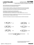
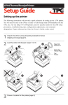
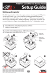
Unpack the printer, saving all packing materials for future shipping or storage (page 11).
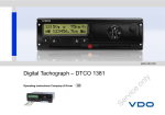
Load the starter roll of paper (pages 12).
Qbqfs!Spmm
Tvqqpsut!)3*
Tubsufs!Spmm
Uifsnbm!Qbqfs
Uftu
Qsjoupvu
Made under one or more of the following U.S. patents: 4886381, 5579043,
5613787, 5651624, 5713678, 5752779, 5789916, 5800080, 5879090,
5887999, 5975776, 6027266, 6085973, 6089450, 6129465, 6155483,
6404452, 6486902, 6504331, 5749277, 6722754, 6739773, 6784909. Other
U.S. and international patents pending.
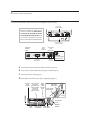
3
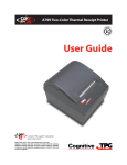
Choose a location for the printer.
4
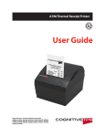
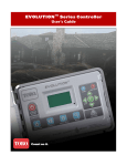
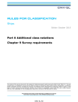
Connect the following cables based on your configuration using a-b below.
Dpoofdups
Joufsgbdf!Qbofm
When using USB (step “b” below), use
caution to ensure the USB cable is
connected to the USB connector
on the back left of the printer and
not into the cash drawer connector
that is on the right back of the printer.
Dpoofdups!Dpwfs
)Pqfo!Qptjujpo*
Qpxfs
Tvqqmz
Dpoofdups
Dpoofdups
Joufsgbdf
Qbofm
VTC
Dpoofdups
ST.343D!Dpnnvojdbujpo
Dpoofdups
):.qjo!tipxo*
Dbti!Esbxfs
Dbcmf
Tusbjo!Sfmjfg
Dbti
Esbxfs
Dpoofdups
DBVUJPO;
EP!OPU!qmvh!uif
VTC!Dbcmf!ifsf/
a Cash drawer (if your installation includes this feature, page 15).
b 9-pin or 25 pin Serial or USB cable (serial: page 16; USB: page 17).
c Connect the power cable (page 18).
d Route cables as shown for your setup configuration (page 19).
Dpoofdups Dpnnvojdbujpo Qpxfs
Dpoofdups
Tvqqmz
Dpwfs
Dbcmf
)Dmptfe* )ST.343D!:.qjo*
)Spvuf!tusbjhiu )Tusbjhiu
pvu!cbdl!pg
cbdl*
qsjoufs!boe
ujhiufo!tdsfxt*
VTC!Dbcmf
Tusbjo!Sfmjfg
Qpxfs!Tvqqmz
Tusbjo!Sfmjfg
VTC
Dbcmf
Dbti!Esbxfs
Dbcmf
VTC
Dbcmf
Qpxfs!Tvqqmz
Tusbjo!Sfmjfg
VTC!Dbcmf
Tusbjo!Sfmjfg
Cbdl!pg
Qsjoufs
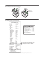
5
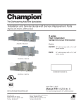
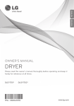
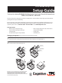
Run a diagnostic test to test the printer (page 19).
Pqfo
Dpwfs
Qvti!boe!ipme
Qbqfs!Gffe!Cvuupo
xijmf!dmptjoh!Dpwfs
6
Configure the printer if necessary (page 20).
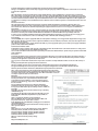
*** A798 – Diagnostics Form ***
Model number
Serial number
:
:
A798-720D-TD00
C073400014
Boot Firmware
Revision+++!B8:6!.!Ejbhoptujdt!Gpsn!+++
: V1.00
CRC
: 08D3
P/N
Npefm!ovncfs : 189-7940154A
; B8:6.322:
Flash Firmware
Tfsjbm!ovncfs
; B123362398
Revision
: V1.00
CRC Cppu!Gjsnxbsf : D70C
P/N
: 189-7940155A
Sfwjtjpo
; W2/13
+++++++++!!NBJO!NFOV!!++++++++++
+++++++++++++++++++++++++++++++
Tfmfdu!b!tvc.nfov!;
.!FYJU
.!Qsjou!Dvssfou!Dpogjhvsbujpo
.!Tfu!Dpnnvojdbujpo!Joufsgbdf
.!Tfu!Ejbhoptujdt!Npeft
.!Tfu!Fnvmbujpo0Tpguxbsf!Pqujpot
.!Tfu!Ibsexbsf!Pqujpot
.!Tfu!Qbqfs!Uzqf
DSD
; 87FC
H/W parameters
Q0O
; 29:.2187187B
Flash Memoriy
Size
:
2
Mbytes
Gmbti!Gjsnxbsf
Flash Logos/Fonts
: 1152 kbytes
Sfwjtjpo
; W2/24
Flash UserDSD
Storage
: 64 kbytes
; BC73
Flash Journal
: 64 kbytes
Q0OSize
; 29:.8:613:1B
SRAM Size
: 128 kbytes
CPU Clock
Freq.
:
50
MHz
I0X!qbsbnfufst
Head setting
: C
Gmbti!Nfnpsz!Tj{f
; 3!Nczuf
Pre-HeatingGmbti!Mphpt0Gpout
: Disabled
; 2135!lczuft
Print Density
:
100%
Gmbti!Vtfs!Tupsbhf
; 1!lczuft
Max SpeedTSBN!Tj{f
: 150 mm/sec
; 367!lczuft
Paper Width
Ifbe!Tfuujoh : 80 mm; E
Max Power
: 55 W ; Uzqf!6-!Wfstjpo!1
!! Qbqfs!Uzqf!Obnf
Knife
: Enabled
Dpmps!Efotjuz!Bek
; 211!&
Partial Cut Qsjou!Efotjuz!)Npop*
: 125 steps
; 211!&
Paper Low Nby!Tqffe
Sensor
: Disabled
; 211!nn0tfd
Qbqfs!Xjeui
; 91!nn
Comm. Interface
Nby!Qpxfs
; 66!X
RX Buffer Size
: 4096 ; Fobcmfe
Lojgf
Interface type
: RS232/USB
Qbsujbm!Dvu
; 246!tufqt
ParametersQbqfs!Mpx!Tfotps
; Ejtbcmfe
Baud Rate
: 115200
Data Dpnn/!Joufsgbdf
Bits
: 8
Stop Bit SY!Cvggfs!Tj{f: 1
; 51:7
Parity Joufsgbdf!uzqf : NONE ; ST3430VTC
Flow Control
:
DTR/DSR
Qbsbnfufst
Reception Errors
Cbve!Sbuf : Ignore ; 226311
USB Driver Type
Ebub!Cjut : Printer ;Class
9
USB Packet w/Error
: Reject ; 2
Tupq!Cju
Qbsjuz
; OPOF
Resident Code Pages
: 437, 850,
852, 857, 858
Gmpx!Dpouspm
; EUS0ETS
860, 863,
865, 866
Sfdfqujpo!Fsspst
; Jhopsf
1252,
862,
737, 874
Bmufsobuf!EUS0ETS ; Ejtbcmfe
When the printer is configured for USB, this
location will show either: “USB Driver Type: Native”,
“USB Driver Type: Printer Class”, or “USB Driver:
Comm Class”.
971-!974-!976-!977
Logo(s) defined
: YES
2363-!973-!848
User Char(s) defined
: NO
Journal Unused
:
64
kbytes
Bwbjmbcmf!Qbqfs!Uzqft
; 11/11!!12/11!!16/11
:
OFF
2!dmjdl
3!dmjdlt
4!dmjdlt
5!dmjdlt
6!dmjdlt
7!dmjdlt
8!dmjdlt
Foufs!dpef-!uifo!ipme!Cvuupo!EPXO
bu!mfbtu!2!tfdpoe!up!wbmjebuf
A715 CP850
Emulation
: Disabled
Sftjefou!Dpef!Qbhft
; 548-!961-!963-!969
Diagnostice
.?
.?
.?
.?
.?
.?
.?
12/:1!!12/:3!!12/:4
Mphp!)t*!efgjofe
; ZFT
To enter Printer
Config Menu :
Dvssfou!Qsjoufs!ubmmjft!bsf
Vtfs!Dibs)t*!efgjofe
; OP
1) Flip DIP
switch #1 down
qsjoufe!bgufs!uif!Ejbhoptujd
2) Reset the printer, while holding
the Paper Feed button down
jogpsnbujpo!boe!xjmm!wbsz
Up!foufs!Qsjoufs!Dpogjh!Nfov!!;
qfs!qsjoufs!vtf/
2*!Gmjq!EJQ!txjudi!$2!epxo
Print Test and3*!Sftfu!uif!qsjoufs-!xijmf!ipmejoh
Configuration Menu Sample. Samples will vary depending on the printer model.
uif!Qbqfs!Gffe!cvuupo!epxo
~
Federal Communications Commission (FCC) Radio Frequency Interference Statement Warning
Changes or modifications to this unit not expressly approved by the party responsible for compliance could void the user’s authority
to operate the equipment.
Note
This equipment has been tested and found to comply with the limits for a Class A digital device, pursuant to Part 15 of the FCC
Rules. These limits are designed to provide reasonable protection against harmful interference when the equipment is operated in
a commercial environment. This equipment generates, uses, and can radiate radio frequency energy and, if not installed and used in
accordance with the instruction manual, may cause harmful interference to radio communications. Operation of this equipment in
a residential area is likely to cause harmful interference in which case the user will be required to correct the interference at his own
expense.
Information to the User
This equipment must be installed and used in strict accordance with the manufacturer’s instructions. However, there is no
guarantee that interference to radio communications will not occur in a particular commercial installation. If this equipment does
cause interference, which can be determined by turning the equipment off and on, the user is encouraged to contact TPG, Inc.
immediately.
TPG, Inc. is not responsible for any radio or television interference caused by unauthorized modification of this equipment or
the substitution or attachment of connecting cables and equipment other than those specified by TPG, Inc. The correction of
interferences caused by such unauthorized modification, substitution or attachment will be the responsibility of the user.
In order to ensure compliance with the Product Safety, FCC and CE marking requirements, you must use the power supply, power
cord, and interface cable which are sold for use with this product or which meet the following parameters:
Power Supply
UL Listed (QQGQ), Class 2 power supply with SELV (Secondary Extra Low Voltage), non-energy hazard output, limited energy source,
input rated 100-240 Vac, 1.5/0.8 A, 50/60 Hz, output rated 24 Vdc, 2.3 A for 55 watt unit; 100-240 Vac, 2.0A, 50/60 Hz, output rate 24
Vdc, 3.125 A for 75 watt unit.
Use of this product with a power supply other than the TPG, Inc. power supply will require you to test the power supply and TPG, Inc.
printer for FCC and CE mark certification.
Communication Interface Cable
A shielded (360 degree) interface cable must be used with this product. The shield must be connected to the frame or earth ground
connection or earth ground reference at EACH end of the cable.
Use of a cable other than described here will require that you test the cable with the TPG, Inc. printer and your system for FCC and CE
mark certification.
Power Cord
A UL listed, detachable power cord must be used. For applications where the power supply module may be mounted on the floor, a
power cord with Type SJT marking must be used. For applications outside the US, power cords which meet the particular country’s
certification and application requirements should be used.
Use of a power cord other than described here may result in a violation of safety certifications which are in force in the country of
use.
Industry Canada (IC) Radio Frequency Interference Statement
This Class A digital apparatus meets all requirements of the Canadian Interference-Causing Equipment Regulations.
Cet appareil numérique de la classe A respecte toutes les exigences du Règlement sur le matériel brouilleur du Canada.
Voluntary Control Council for Interference (VCCI) Radio Frequency Interference Statement
This is a Class A product based on the standard of the Voluntary Control Council for
Interference by Information Technology Equipment (VCCI). If this equipment is used in
a domestic environment, radio disturbance may arise. When such trouble occurs, the
user may be required to take corrective actions.
Disclaimer
Information in this document is subject to change without notice.
Consult your TPG, Inc. sales representative for information that
is applicable and current. TPG, Inc. reserves the right to improve
products as new technology, components, software, and firmware
become available.
No part of this document may be reproduced, transmitted, or
translated in any form or by any means, electronic or mechanical,
for any purpose without the express written permission of TPG, Inc.
Copyright
Copyright © 2007 by TPG - Transaction Printer Group, a subsidiary
of ATSI Holdings, Inc.
950 Danby Road, Ithaca, New York 14850, USA. All rights reserved.
Printed in USA. Confidential, Unpublished. Property of TPG, Inc.
Trademarks
TPG™ is a trademark of TPG, Inc.and its subsidiaries.
Microsoft, Windows NT are registered Trademarks of Microsoft
Corporation in the U.S.A. and/or other countries.
Inside Out Networks, Inside Out, EPIC, and Edgeport are trademarks
of Inside Out Networks.
All other trademarks and registered trademarks are the property of
their respective holders.
Patents
Made under one or more of the following U.S. patents: 4886381,
5579043, 5613787, 5651624, 5713678, 5752779, 5789916,
5800080, 5879090, 5887999, 5975776, 6027266, 6085973,
6089450, 6129465, 6155483, 6404452, 6486902, 6504331,
5749277, 6722754, 6739773, 6784909.
Other U.S. and international patents pending.
Web Site
http://www.TPGprinters.com
A798 - SUG0001 Rev. A
10/07
Printed in the United States