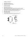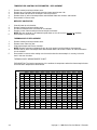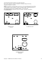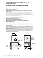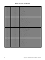
1
SERVICE MANUAL
(DOMESTIC)
IMPINGER CONVEYOR OVENS
MODEL SERIES 1000 - 1200 & 1400
Lincoln Foodservice Products, LLC
1111 North Hadley Road
Fort Wayne, Indiana 46804
United States of America
Phone : (800) 374-3004
U.S. Fax: (888) 790-8193 • Int’l Fax: (260) 436-0735
Technical Service Hot Line
(800) 678-9511
www.lincolnfp.com
1000SeriesSvc
REV: 1/5/07
TABLE OF CONTENTS
TABLE OF CONTENTS..............................................................................................................................................2
SEQUENCE OF OPERATIONS 1000/1001/1004/1005/1200/1201/1204/1205 ........................................................3
SEQUENCE OF OPERATIONS 1022 / 1023 / 1202 / 1203 ......................................................................................4
SEQUENCE OF OPERATIONS 1040 / 1041 / 1240 / 1241 ......................................................................................5
SCHEMATIC / 1000, 1001 .........................................................................................................................................8
SCHEMATIC / 1004, 1005 .........................................................................................................................................9
SCHEMATIC / 1022, 1023 – S/N Q19077 & BELOW ..............................................................................................10
SCHEMATIC / 1022, 1023 – S/N Q19078 & ABOVE...............................................................................................11
SCHEMATIC / 1040, 1041 – S/N Q14279 & BELOW ..............................................................................................12
SCHEMATIC / 1040, 1041 – S/N Q14280 & ABOVE...............................................................................................13
SCHEMATIC / 1200, 1201 .......................................................................................................................................14
SCHEMATIC / 1202, 1203 S/N Q14790 & BELOW .................................................................................................15
SCHEMATIC / 1202, 1203 S/N Q14791 & ABOVE..................................................................................................16
SCHEMATIC / 1204, 1205 .......................................................................................................................................17
SCHEMATIC / 1240, 1241 – S/N Q14279 & BELOW ..............................................................................................18
SCHEMATIC / 1240, 1241 – S/N Q14280 & ABOVE...............................................................................................19
TROUBLESHOOTING GUIDE 1000 & 1200 ...........................................................................................................20
GAS OVENS .........................................................................................................................................................20
TROUBLESHOOTING GUIDE .................................................................................................................................25
ELECTRIC OVENS MODEL SERIES 1000 & 1200 .............................................................................................25
REMOVAL, INSTALLATION & ADJUSTMENTS .....................................................................................................32
PARTS / MODEL SERIES 1000 & 1200 - GENERAL..............................................................................................60
BLOW UP / 1000, 1200 – GENERAL.......................................................................................................................61
PARTS / ACCESS DOOR & 1050 DOOR................................................................................................................62
BLOW UP / ACCESS DOOR & 1050 DOOR ...........................................................................................................63
PARTS / MODEL 1000,1001,1050,1051,1004, &1005 – S/N 100 TO 4389 ............................................................64
BLOW UP / 1000, 1001, 1050, 1051, 1004, & 1005 S/N 100 TO 4389 ...................................................................65
PARTS / MODEL 1000,1001,1004, AND 1005 S/N 4390 & ABOVE .......................................................................66
BLOW UP 1000, 1001, 1004, 1005 S/N 4390 & ABOVE .........................................................................................67
PARTS / 1022-1023..................................................................................................................................................68
BLOW UP / 1022, 1023 ............................................................................................................................................69
PARTS / 1040-1041..................................................................................................................................................70
BLOW UP / 1040, 1041 ............................................................................................................................................71
PARTS / 1200, 1201, 1204 AND 1205 .....................................................................................................................72
BLOW UP / 1200, 1201, 1204, 1205 ........................................................................................................................73
PARTS / 1202-1203..................................................................................................................................................74
BLOW UP / 1202, 1203 ............................................................................................................................................75
PARTS / 1240-1241..................................................................................................................................................76
BLOW UP / 1240, 1241 ............................................................................................................................................77
PARTS / OVEN BACK - GAS ...................................................................................................................................78
BLOW UP / OVEN BACK – GAS .............................................................................................................................79
PARTS / OVEN BACK- ELECTRIC..........................................................................................................................80
BLOW UP / OVEN BACK – ELECTRIC ...................................................................................................................81
PARTS / CONVEYOR MOTOR ASSEMBLY S/N 4390 & ABOVE ..........................................................................82
BLOW UP / CONVEYOR MOTOR ASSEMBLY S/N 4390 & ABOVE .....................................................................83
PARTS / SERIES 1000 – CONVEYOR....................................................................................................................84
BLOW UP / SERIES 1000 CONVEYOR ..................................................................................................................85
PARTS / SERIES 1200 - CONVEYOR CONTROL..................................................................................................86
BLOW UP / SERIES 1200 – CONVEYOR CONTROL ............................................................................................87
PARTS / SERIES 1200 – CONVEYOR....................................................................................................................88
BLOW UP / SERIES 1200 – CONVEYOR ...............................................................................................................89
2
Impinger I -–1000 Series Service Manual - Domestic
SEQUENCE OF OPERATIONS 1000/1001/1004/1005/1200/1201/1204/1205
MODEL 1000 - 120/230 VAC - 60HZ - NATURAL GAS
MODEL 1001 - 120/230 VAC - 60HZ - L.P. GAS
MODEL 1004 - 120/230 VAC - 60HZ - NATURAL GAS
MODEL 1005 - 120/230 VAC - 60HZ - L.P. GAS
MODEL 1200 - 120/230 VAC - 60HZ - NATURAL GAS/DUAL BELT
MODEL 1201 - 120/230 VAC - 60HZ - L.P. GAS/DUAL BELT
MODEL 1204 - 120/230 VAC - 60HZ - NATURAL GAS/DUAL BELT
MODEL 1205 - 120/230 VAC - 60HZ L.P.GAS/DUAL BELT
POWER SUPPLY
CONTROL BOX AUTO
COOL DOWN
MAIN FAN CIRCUIT
TRANSFORMER (12.6
VAC)
BURNER CIRCUIT
CONVEYOR DRIVE(S/N
100 to 4389)
(S/N 4390 and UP)
Electrical Power to be supplied to the Oven by a four conductor service. . Voltage
from the black conductor to the white conductor is 120 VAC.
Black conductor is Hot
Red conductor is Hot
White conductor is Dedicated Neutral
Green conductor is Ground
When the temperature in the Control Box reaches 120°F + 3°, the Cooling Fan
Thermostat will switch power to the Control Box Cooling Fan. The Thermostat will
interrupt power to the Cooling Fan when the Control Box temperature falls to 100°F +
3°.
Electrical power is permanently supplied to the normally open contacts of the Double
Pole Main Fan Relay, the Cooling Fan Thermostat, the normally open Main Fan
Switch, and the normally open Cool Down Thermostat (thermostat closes at 160°F
and opens at 140°F). Closing the Main Fan Switch energizes the coil of the Relay.
The normally open contacts now close, energizing the Main Fan Motor through (2)
10A fuses, and the Cooling Fan. Closing the Fan Switch also supplies power to the
Hour Meter (hour meter discontinued after S/N 3484), the 12.6 VAC Transformer, the
Burner and Conveyor Switches.
Upon closure of the Fan Switch, 120 VAC is supplied to the primary of the 12.6 VAC
Transformer. The Transformer steps the voltage down to 12.6 VAC (normally 13 to
14 VAC) with a center tap, and supplies power to the Time/Temp Display. The
voltage from each leg of the Transformer'
s secondary to the center tap should be
one half of the secondary voltage.
Closing the Fan Switch and the normally open Burner Switch supplies 120 VAC
through the Air Pressure Switch, to the normally open contacts of the Burner Motor
Relay, and the primary of the 24 VAC Step Down Transformer. The Transformer
secondary supplies 24 VAC (through a 1A fuse on Model 1004 and 1005) to the
Relay Coil (the normally open contacts close within 30 seconds), and the normally
open Centrifugal Switch. When the Relay contacts close, the Burner Blower Motor is
energized. As this motor reaches approximately1600 R.P.M., its internal centrifugal
switch closes, supplying 24 VAC to the Gas Control Valve. When the Gas Control
Valve is supplied with 24 VAC the pilot valve is energized, and the ignitor circuit is
energized. Ignition should now occur. After pilot flame is proven, the main gas valve
is energized. The Burner Indicator Light is also energized.
Closing the Fan Switch and the normally open Conveyor Switch supplies 120 VAC
through a 3A Fuse, to the Motor Control Board. AC volts are converted to D.C. volts
and are supplied to the Conveyor motor at board terminals A1 and A2 through a
D.P.D.T. Reversing Switch. Adjustment of the Speed Control Potentiometer (500
ohm, 10 turn) will change resistance at terminals S1, S2, and S3 varying the D.C.
voltage to the motor. The speed of the Conveyor Motor will increase or decrease as
the D.C. voltage from the Motor Control Board increases or decreases respectively.
Closing the fan switch and the normally open conveyor switch supplies 120 VAC to
the Motor Control Board. AC volts are converted to DC volts and are supplied to the
Conveyor Motor at terminals A+ and A-. Adjustment of the Speed Control
Potentiometer (5,000 ohm 10 turn ) will change resistance at terminals P1, P2, and
P3 varying the DC voltage to the motor. The speed of the conveyor motor will
increase or decrease as the DC voltage from the board increases or decreases
respectively. As the motor turns, it drives both the reducer gearbox and the tach.
Impinger I -–1000 Series Service Manual - Domestic
3
NOTE
TIME TEMP DISPLAY
generator. The tach. generator is a DC voltage generator which supplies a voltage to
the DC motor control board and is used as a reference for maintaining a constant
conveyor speed.
The 1200 Series Ovens utilize 2 complete conveyor drive systems.
The Time/Temp. Display is energized when the Fan Switch is closed, supplying120
VAC to the primary of the 12.6 volt Transformer The secondary output of the
transformer, normally 13 to 14 VAC (depending on input), with a center tap is
supplied at terminals 1,2, and 3 of the Time/Temp. Display. The center tap is
terminal 2. The display works on a balanced input and center tap voltage to each leg
must be 1/2 the total reading.
The speed side of the Time/Temp. Display uses a slotted disc (cemented to tach.
coupling) to break the infra-red light beam of the optical switch (mounted on gear
motor) producing electrical pulses that are transmitted to the display. The display
converts these pulses into a read-out of minutes and seconds. The temperature
portion of the display uses a Thermistor Probe to sense oven temperature. The
thermistor outputs a resistance proportional to the oven temperature. This resistance
is then converted by the display into a temperature reading.
NOTE: The 1200 Series Ovens use a Double Pole Double Throw Switch to connect
the two Optical Encoder Assemblies to the Time/Temp Display. By activating the
switch, either the front or rear belt speed can be shown by the Time/Temp Display.
SEQUENCE OF OPERATIONS 1022 / 1023 / 1202 / 1203
MODEL 1022 - 120/208 VAC - 3 PHASE
MODEL 1023 - 120/240 VAC - 3 PHASE
MODEL 1202 - 120/208 VAC - 3 PHASE - DUAL BELT
MODEL 1203 - 120/240 VAC - 3 PHASE - DUAL BELT
POWER SUPPLY
Electrical Power to be supplied to the Oven by a five conductor service. Voltage from
the black conductor to the white conductor is 120 VAC.
Black conductor is Hot
Red conductor is Hot
Orange conductor is Hot
White conductor is Dedicated Neutral
Green conductor is Ground
MAIN FAN CIRCUIT
Electrical power is permanently supplied through 6, 50A fuses to the normally open
contacts of the Mercury Contactors. Power is also supplied through 2, 15A fuses to
the normally open contacts of the Double Pole Main Fan Relay, the Double Pole
Main Fan Switch, and the normally open Cool-Down Thermostat (thermostat closes
at 160°F and opens at 140°F.) Closing the Main Fan Switch energizes the coil of the
Main Fan Relay. The normally open contacts now close, energizing the Main Fan
Motor, and the Control Box Cooling Fan. Closing the Fan Switch also supplies power
to the Hour Meter (hour meter discontinued after S/N 3484), the 12.6 VAC
Transformer, the Heat and Conveyor Switches.
Upon closure of the Fan Switch, 120 VAC is supplied to the primary of the 12.6 VAC
Transformer. The Transformer steps the voltage down to 12.6 VAC (normally 13 to
14 VAC) with a center tap, and supplies power to the Time/Temp Display. The
voltage from each leg of the Transformer'
s secondary to the center tap should be
one half of the secondary voltage.
Closing the Fan Switch and the normally open Heat Switch supplies 120 VAC
through the Air Pressure Switch and the normally closed Hi-Limit Thermostat
(manually re-settable, opens at 190°F) the 3A Fuse, to the L1 terminal of the
Temperature Control Board, the coils of the Mercury Contactors, and to the Heat
Indicator Light.
When the Heat Switch is closed, 120 VAC is supplied to the Temperature Control.
The Temperature Control Potentiometer (2.5K ohm) is adjusted to desired
temperature. The Thermocouple will provide varying millivolts to the Temperature
Controller. The Temperature Controller switches the L2 line of the Contactor coils at
intermittent intervals to maintain desired temperature.
TRANSFORMER (12.6
VAC)
HEAT CIRCUIT
TEMPERATURE
CONTROL
4
Impinger I -–1000 Series Service Manual - Domestic
CONVEYOR DRIVE
(S/N 100 to 4389)
(S/N 4390 and UP)
NOTE*
TIME/TEMP DISPLAY
NOTE*
Closing the Fan Switch and the normally open Conveyor Switch supplies 120 VAC
through a 3A Fuse, to the Motor Control Board. AC volts are converted to D.C. volts
and are supplied to the Conveyor Motor at board terminals A1 and A2 through a
D.P.D.T. Reversing Switch. Adjustment of the Speed Control Potentiometer (500
ohm, 10 turn) will change resistance at terminals S1, S2, and S3 varying the D.C.
voltage to the motor. The speed of the Conveyor Motor will increase or decrease as
the D.C. voltage from the Motor Control Board increases or decreases respectively.
Closing the fan switch and the normally open conveyor switch supplies 120 VAC to
the Motor Control Board. AC volts are converted to DC volts and are supplied to the
Conveyor Motor at terminals A+ and A-. Adjustment of the Speed Control
Potentiometer (5,000 ohm 10 turn) will change resistance at terminals P1, P2, and
P3 varying the DC voltage to the Conveyor Motor. The speed of the conveyor motor
will increase or decrease as the DC voltage from the board increases or decreases
respectively. As the motor turns, it drives both the reducer gearbox and the tach.
generator. The tach. generator is a DC voltage generator which supplies a voltage to
the DC motor control board and is used as a reference for maintaining a constant
conveyor speed.
The 1200 Series Ovens utilize 2 complete conveyor drive systems.
The Time/Temp Display is energized when the Fan Switch is closed, supplying 120
VAC to the primary of the12.6 volt Transformer. The secondary output of the
transformer, normally 13 to 14 VAC (depending on input), with a center tap is
supplied to terminals 1,2, and 3 of the Time/Temp Display. The center tap is terminal
2. The display works on a balanced input and center tap voltage to each leg must be
1/2 the total reading.
The speed side of the Time/Temp. Display uses a slotted disc (cemented to tach.
coupling) to break the infra-red light beam of the optical switch (mounted on gear
motor) producing electrical pulses that are transmitted to the display. The display
converts these pulses into a read-out of minutes and seconds.
The temperature portion of the display uses a Thermistor Probe to sense oven
temperature. The thermistor outputs a resistance proportional to the oven
temperature. This resistance is then converted by the display into a temperature
reading.
The 1200 Series Ovens use a Double Pole Double Throw Switch to connect the two
Optical Encoder Assemblies to the Time/Temp. Display. By activating the switch,
either the front or rear belt speed can be shown by the Time/Temp. Display.
SEQUENCE OF OPERATIONS 1040 / 1041 / 1240 / 1241
MODEL 1040 - 120/230 VAC - 60HZ
MODEL 1041 - 120/230 VAC - 60HZ
MODEL 1240 - 120/230 VAC - 60HZ
MODEL 1241 - 120/230 VAC - 60HZ
POWER SUPPLY
CONTROL BOX AUTO
COOL DOWN
MAIN FAN CIRCUIT
- NATURAL GAS
- L.P. GAS
- NATURAL GAS/DUAL BELT
- L.P. GAS/DUAL BELT
Electrical Power to be supplied to the Oven by a four conductor service. Voltage
from the black conductor to the white conductor is 120 VAC.
Black conductor is Hot
Red conductor is Hot
White conductor is Dedicated Neutral
Green conductor is Ground
When the temperature in the Control Box reaches 120°F ± 3°, the Cooling Fan
Thermostat will switch power to the Control Box Cooling Fan. The Thermostat will
interrupt power to the Cooling Fan when the Control Box temperature falls to 100°F +
3°.
Electrical power is permanently supplied to the normally open contacts of the Double
Pole Main Fan Relay, the Cooling Fan Thermostat, the normally open Main Fan
Switch, and the normally open Cool Down Thermostat (thermostat closes at 160°F
and opens at 140°F). Closing the Main Fan Switch energizes the coil of the Relay.
The normally open contacts now close, energizing the Main Fan Motor through two
10A fuses, and the Cooling Fan. Closing the Fan Switch also supplies power to the
12.6 VAC Transformer, the Burner and Conveyor Switches.
Impinger I -–1000 Series Service Manual - Domestic
5
TRANSFORMER (12.6
VAC)
BURNER CIRCUIT
TEMPERATURE
CONTROL
CONVEYOR DRIVE
(S/N Q14790 & Below,
1200 series
S/N Q14973 & Below
1000 series)
(S/N Q14791 & Above,
1200 series refer to Pg.
5 & 6 S/N Q14974 &
Above, 1000 series refer
to Pg. 5 & 6 (STEPPER)
NOTE:
TIME/TEMP
DISPLAY(S/N Q14790 &
Below, 1200 series
S/N Q14973 & Below
1000 series)
(S/N Q14791 & Above,
1200 series refer to Pg.
5 & 6 S/N Q14974 &
Above, 1000 series refer
to Pg. 5 & 6 (STEPPER)
NOTE*
CONVEYOR DRIVE
6
Upon closure of the Fan Switch, 120 VAC is supplied to the primary of the 12.6 VAC
Transformer. The Transformer steps the voltage down to 12.6 VAC (normally 13 to
14 VAC) with a center tap, and supplies power to the Time/ Temp. Display. The
voltage from each leg of the Transformer'
s secondary to the center tap should be
one half of the secondary voltage.
Closing the Fan Switch and the normally open Burner Switch supplies 120 VAC
through the Air Pressure Switch, to the Temperature Control Board, the normally
open contacts of the Burner Motor Relay (Burner Motor Relay discontinued after S/N
14791) and the primary of the 24 VAC Transformer. The transformer'
s secondary
supplies 24 VAC to the burner motor relay coil (the normally open contacts close
within 30 seconds), and the normally open Centrifugal Switch. When the relay
contacts close, the Burner Blower Motor is energized. As this motor reaches approx.
1,600 R.P.M its internal centrifugal switch closes, supplying 24 VAC to the Gas
Control Valve. When the Gas Control Valve is supplied with 24 VAC, the pilot valve
is energized, and the igniter circuit is energized. Ignition should now occur. After pilot
flame is proven, the Main Gas Valve is energized. The Burner Indicator Light is also
energized.
Closing the Fan Switch and Burner Switch supplies 120 VAC to the Temperature
Control Board. The 1K or 1000 ohm Temperature Potentiometer is adjusted to
desired temperature. The Thermocouple will provide varying millivolts to the
Temperature Controller. The Temperature Controller supplies 120 VAC to the
Solenoid Valve at intermittent intervals to maintain desired temperature.
Closing the fan switch and the normally open conveyor Switch supplies 120 VAC to
the Motor Control Board. AC volts are converted to DC volts and are supplied to the
Conveyor Motor, at terminals A+ and A-. Adjustment of the Speed Control
Potentiometer (5,000 ohm 10 turn) will change resistance at terminals P1, P2, and
P3 varying the DC voltage to the Conveyor Motor. The speed of the conveyor motor
will increase or decrease as the DC voltage from the board increases or decreases
respectively. As the motor turns, it drives both the reducer gearbox and the tach.
generator. The tach. Generator is a DC voltage generator, which supplies a voltage
to the DC motor control board and is used as a reference for maintaining a constant
conveyor speed.
The 1200 Series Ovens utilize 2 complete conveyor drive systems.
The Time/Temp. Display is energized when the Fan Switch is closed, supplying 120
VAC to the primary of the12.6 volt Transformer. The secondary output of the
transformer, normally 13 to 14 VAC (depending on input), with a center tap, is
supplied to terminals 1,2, and 3 of the Time/Temp. Display. The center tap is
terminal 2. The display works on a balanced input and center tap voltage to each leg
must be 1/2 the total reading.
The speed side of the Time/Temp. Display uses a slotted disc (cemented to tach.
coupling) to break the infrared light beam of the optical switch (mounted on gear
motor) producing electrical pulses that are transmitted to the display. The display
converts these pulses into a read-out of minutes and seconds. The temperature
portion of the display uses a Thermistor Probe to sense oven temperature. The
thermistor outputs a resistance proportional to the oven temperature. This resistance
is then converted by the display into a temperature reading.
The 1200 Series Ovens use a Double Pole Double Throw Switch to connect the two
Optical Encoder Assemblies to the Time/Temp. Display. By activating the switch,
either the front or rear belt speed can be shown by the Time/Temp Display .
Closing the Oven Fan Switch supplies 120 VAC, through the Power Transformer, to
the normally open Conveyor Switch. Closing the Conveyor Switch supplies 120 VAC,
through a 3 AMP Fuse, to the primary of the Conveyor Control Transformer. The
secondary of this Transformer supplies 10 VAC and 29 VAC to the Conveyor
Control. The conveyor control supplies voltage pulses to the Conveyor Control. The
Conveyor Control Potentiometer varies the frequency of these pulses. The motor
speed will increase or decrease, as the frequency of the pulses increase or decrease
respectively.
Impinger I -–1000 Series Service Manual - Domestic
TIME TEMP DISPLAY
Closing the Oven Fan Switch supplies 120 VAC, through the Power Transformer, to
the primary of the Time/Temp. Transformer. The secondary output of the
Transformers, 12.5to 15 VAC with a center tap, is supplies to terminals 1, 2, and3 of
the Time/Temp. Display. The display works on a balanced input, and the center tap
voltage to each leg must be 1/2 the total reading.
Impinger I -–1000 Series Service Manual - Domestic
7
SCHEMATIC / 1000, 1001
8
Impinger I -–1000 Series Service Manual - Domestic
SCHEMATIC / 1004, 1005
Impinger I -–1000 Series Service Manual - Domestic
9
SCHEMATIC / 1022, 1023 – S/N Q19077 & BELOW
10
Impinger I -–1000 Series Service Manual - Domestic
SCHEMATIC / 1022, 1023 – S/N Q19078 & ABOVE
Impinger I -–1000 Series Service Manual - Domestic
11
SCHEMATIC / 1040, 1041 – S/N Q14279 & BELOW
12
Impinger I -–1000 Series Service Manual - Domestic
SCHEMATIC / 1040, 1041 – S/N Q14280 & ABOVE
Impinger I -–1000 Series Service Manual - Domestic
13
SCHEMATIC / 1200, 1201
14
Impinger I -–1000 Series Service Manual - Domestic
SCHEMATIC / 1202, 1203 S/N Q14790 & BELOW
Impinger I -–1000 Series Service Manual - Domestic
15
SCHEMATIC / 1202, 1203 S/N Q14791 & ABOVE
16
Impinger I -–1000 Series Service Manual - Domestic
SCHEMATIC / 1204, 1205
Impinger I -–1000 Series Service Manual - Domestic
17
SCHEMATIC / 1240, 1241 – S/N Q14279 & BELOW
18
Impinger I -–1000 Series Service Manual - Domestic
SCHEMATIC / 1240, 1241 – S/N Q14280 & ABOVE
Impinger I -–1000 Series Service Manual - Domestic
19
TROUBLESHOOTING GUIDE 1000 & 1200
GAS OVENS
SYMPTOM
Oven fan will not run
POSSIBLE CAUSE
Incoming Power Supply
NOTE:
(Export Ovens)
Oven Fan Fuse(s)
Fuse Holder
Fan Switch
Main Relay
Fan Motor
No Main Fan Cool
Down
No Control Box
Cooling(For ovens
equipped with Control
Box Cooling Fan)
Capacitor
Cool Down Thermostat
Main Fan Relay
(Export Ovens)
Axial Cooling Fan
NOTE:
No automatic control
box cooling (For ovens
equipped with control
box cooling fan)
Incoming Power Supply
Cooling Fan Thermostat
Axial Cooling Fan
Control box cooling fan
continues to run
Oven will not heat
Cooling Fan Thermostat
Gas Supply
Manual Gas Shut-off Valve
Fan Switch
Main Oven Fan
Burner Switch
20
EVALUATION
Check breakers/ Reset if required / Call Power Co.
if needed.
For some export ovens, there is a control circuit
step-down transformer. This transformer steps
down supply voltage to 120 VAC. If main fan will
not run, the secondary of this transformer must be
checked for 120 VAC output. Check specific oven
model schematic for circuit location.
Check and/or Replace
Check and/or Replace
Check continuity between switch terminals.
Check continuity to 120 VAC coil. Check for power
to relay coil (120 VAC). Check for 208/240 VAC to
relay terminals. Visually check for contact pull-in.
Check for opens, shorts, or grounds. WITH
POWER OFF: Turn Fan Blade to check for locked
rotor.
Check for opens, shorts, or grounds.
Check cool down thermostat (thermostat closes at
160°F and opens at 140°F). Check for power (120
VAC) at cool down thermostat. With the cool down
thermostat pre-heated, check for continuity. If
switch is open, replace.
Check for power to Main Fan Relay. Visually check
for contact pull in.
(For ovens equipped with a control circuit stepdown transformer, the supply voltage for the
cooling fan is 240 VAC.)
WITH POWER OFF: check for locked rotor. Check
for power (120 VAC) to cooling fan. If 120 VAC is
present at the fan motor and the fan does not run,
replace fan assembly.
Check breakers/Reset if needed. Check for
incoming power (120 VAC)at cooling fan
thermostat.
Check cooling fan thermostat (thermostat closes at
120°F and opens at 100°F). With cooling fan
thermostat pre-heated, check for continuity. If
switch is open, replace.
Check for 120 VAC to cooling fan, if present and
fan does not run, replace fan.
See "Cooling Fan Thermostat"
Check for adequate gas supply to oven.
Check to see that manual shut-off valve is open.
Check to see that fan switch is "on".
Check if main oven fan is operating. If not, refer to
"Oven fan will not run". Page 20.
Check for 120 VAC to neutral on both sides of
switch. If switch is closed and 120 VAC is present
on one side only, replace the switch.
Impinger I -–1000 Series Service Manual - Domestic
Air Pressure Switch
Transformer, 24 VAC
NOTE:
(Model 1004 & 1005)
Burner Motor Relay
Burner Blower Motor
Centrifugal Switch of Burner
Blower Motor
For ovens with
Johnson Controls
Ignition Control
Ignition Control and Valve
Assembly
(For ovens with
Honeywell Ignition
control, See Pg. 21)
No Pilot
Pilot Shut-off Valve
Pilot Tube
Pilot Orifice
Burner Ignitor
Impinger I -–1000 Series Service Manual - Domestic
Check for 120 VAC on both sides of switch. If
voltage present on one side only, check for air tube
blockage. Adjust air switch. If above fails, replace
air pressure switch.
Check for 120 VAC to primary of transformer.
Check for 24 VAC from secondary of transformer. If
there is primary voltage, but no secondary voltage,
replace transformer.
For oven models 1004 and 1005, there is a 1 Amp
fuse located between the 24 VAC output from the
transformer and the coil of the burner motor relay. If
there is 24 VAC output from the transformer, but no
burner motor relay action, check fuse and fuse
holder. Replace as necessary.
Delete burner motor relay refer to Section D, Page
34.
Check for 120 VAC supply to burner blower motor.
If 120 VAC is present and motor does not run,
replace motor. WITH POWER OFF: turn blower
wheel to check for locked rotor.
Check for 24 VAC output from secondary of
transformer. If voltage is present, check for 24 VAC
at pin 6 and the ground bar on ignition control and
valve assembly. If the burner blower motor is
running and there is no voltage at pin 6 and the
ground bar on the ignition control valve, replace the
burner blower motor.
Check for 24 VAC supply to the ignition control and
valve assembly at pin 6 and the ground bar. If
voltage is present, check for 24 VAC across pin #1
and the ground bar (pilot valve). If voltage is not
present, replace electronic control package. If the
pilot valve is energized, check to see that the high
voltage ignitor circuit is also energized. To check,
disconnect the ignitor lead from the bottom of
ignition control. Place female terminal of ignitor
lead approximately 1/8" from terminal post on
ignition control. Spark should jump the 1/8" gap. If
no spark is present, replace ignition control.
If the ignition control is supplied with 24 VAC, and
the pilot valve (internal to valve assembly) and
ignitor circuits are energized, visually check for pilot
flame. This may be done by opening the small
inspection door on the end of the burner, or by
opening the main oven door and looking under the
lower finger housings on the right side of the oven.
If no pilot flame is visible, check the following.
Check to see that pilot shut-off valve is open (shutoff valve is located between ignition control and
valve assembly and burner.)
Check for gas pressure at pilot tube. Disconnect
pilot tube at burner and connect manometer to pilot
tube. If no gas pressure is present, check for
blockage in pilot tube or pilot shut-off valve. If these
are clear, and there is gas supplied to the oven,
replace the ignition control and valve assembly.
If there is gas pressure at the pilot tube, check the
pilot orifice for obstructions. Replace as need
Check the burner ignitor head for any obstructions,
also check for frayed or broken wire, any type of
damage to spark gap (.100 in. 2.5 m.m.) If there is
visible damage, replace ignitor assembly.
21
Pilot flame but no main
flame
Flame Sensor
Ignition Control and Valve
Assembly
For ovens with
Honeywell ignition
control
Centrifugal Switch of Burner
Blower Motor
NOTE:
Ignition Control
No Pilot
Pilot Shut-off Valve
Pilot Tube
Pilot Orifice
Burner Ignitor
22
(There should be a visible pilot flame at this time.)
To check for proper flame sensor operation,
connect a digital multimeter (capable of measuring
D. C. microamperes) in series between the flame
sensor wire (normally connected to terminal #4)
and terminal #4. NOTE: This is a current
measurement and the meter must be connected in
series. This procedure is for checking the pilot
flame only. Remove main valve wire (Red) from
terminal #3 on ignition control. With a visible pilot
flame, the current readings should be as follows:
Johnson G-65 control, 0.2 micro amp. D.C.
minimum/Johnson G-60 control, 0.7 micro amp.
D.C. minimum. If these values are not achieved,
replace flame sensor. Also check for any type of
damage to flame sensor wire and connections.
If there is a pilot flame, and there is sufficient micro
amp. current at terminal #4, check for 24 VAC
that the main valve (internal to valve assembly) has
opened. Connect a manometer to the manifold gas
pressure tap located on the back side of the ignition
control and valve assembly. If no gas is present,
replace ignition control and valve assembly.
Check for 24 VAC output from secondary of
transformer. If voltage is present, check for 24 VAC
at terminals marked "24V" and "24V gnd" on
Ignition Control. If the Burner Blower Motor is
running and there is no voltage at terminals 24V
and 24V gnd on the ignition control, replace the
Burner Blower Motor.
These Ignition Controls have a 30 second prepurge(Delay) and a 15 second lock-out time – The
Ignition Control will try for ignition for 15 seconds
and then shut-off. To Re-try for ignition, turn off
burner switch, wait 30 seconds and re-try ignition.
Check for 24 VAC supply to ignition control at
terminals "24V" and "24V gnd". If voltage is
present, check for 24V at terminal "P.V. (Pilot
Valve) and "gnd". If voltage is not present, replace
Ignition Control. If the pilot valve is energized,
check to see that the high voltage ignitor circuit is
also energized. To check, disconnect the ignitor
lead from the ignition control. Place the terminal of
ignitor lead approximately 1/8" from terminal post
on Ignition Control. Spark should jump the 1/8"
gap. If no spark is present, replace ignition control.
If the ignition control is supplied with 24 VAC and
the pilot valve (in gas valve) and ignitor circuits
If no pilot flame is visible, check to see that the pilot
shut-off valve is open(shut-off valve is located
between gas valve and burner).
Check for gas pressure at pilot tube. Disconnect
pilot tube at burner and connect manometer to pilot
tube. If no gas pressure is present, check for
blockage in pilot tube or pilot shut-off valve.
If there is gas pressure at the pilot tube, check the
pilot orifice for obstructions. Replace as needed.
Check the burner ignitor head for any obstructions,
also check for frayed or broken wire, any type of
damage to spark gap (.100 in. 2.5 mm) If there is
visible damage, replace ignitor assembly.
Impinger I -–1000 Series Service Manual - Domestic
(There should be a visible pilot flame at this time).
NOTE: The Honeywell Ignition Control uses the
spark ignitor as the flame sensor. If spark
continues, check for proper ground connections at
Ignition Control. Check pilot orifice for any partial
blockage. If the above checks OK, replace ignition
control. If spark stops when pilot is lit, check for 24
VAC across M.V. - M.V/ P.V. terminals, if voltage is
not present, replace ignition control. If voltage is
present at terminals M.V. - M.V./P.V., the indicator
light on the control panel should be on, verify that
the main valve has opened, connect manometer to
manifold gas pressure tap(located on the
Red Indicator Light is
Temperature Control Valve
Check for gas supply at temperature control. Check
on, but no main
(Robert Shaw)
for temperature control set above 300°F.
flame(For ovens with Main Orifice
Check for blockage of main orifice. If there is no
mechanical
blockage to the main orifice, replace the
thermostat)
temperature control.
(For ovens with
Temperature Control
Check for 120 VAC across L1 and L2on
Electronic
Potentiometer
temperature control board. Potentiometer (1000
Temperature Control)
ohm,1 turn) WITH POWER OFF: check ohms
across red and black leads, the ohm reading
should be 0 to1000 ohms as the dial is turned.
From green to red, the reading should be 1000
ohms steady throughout the full turn of the dial.
NOTE: Ovens S/N Q18037 and above, the potentiometer is internal to temperature control. Proceed to next
component.
Thermocouple Probe
Remove thermocouple leads from the temperature
control board, and measure the millivolt output of
these leads. Refer to chart on page 38 in the
adjustment section for proper readings.
Temperature Control
Turn temperature control dial to full "on" position.
Measure for 120 VAC across terminals "N.O." and
"L2", if voltage is not present; replace control.
Solenoid Valve
If voltage is present at terminals "N.O."and "L2",
check for voltage at solenoid valve. If voltage is
present, listen for valve to open and close. Also,
check for opens and shorts in coil. If solenoid valve
is defective, replace
Intermittent Heating
Both the main fan motor and burner blower motor
are equipped with thermo-protection and will cease
to operate when not cooled properly. This can
cause the units to cycle on and off intermittently.
Also, most of the problems listed under "oven will
not heat" can cause intermittent failures.
Pilot flame but no main
flame
Spark Ignitor (Flame Sensor)
For continuing intermittent problems, a series of test lights may be made and installed in
the ovens. The lights will allow the customer to advise the service technician a trouble code when
the oven fails.
The lights should be connected in the following manner:
Light#l attached in 120VAC line after Air Pressure Switch.
Light#2 attached after 120VAC contacts of Burner Motor Relay (or, refer to Bulletin #028
for Relay Removal).
Light#3 in 24VAC Burner Transformer Secondary.
Light#4 in 24VAC at terminal #6 of Johnson control valve or "24V" on Honeywell Control.
Light#5 in 24VAC at terminal #1 of Johnson control valve or "PV" on Honeywell Control.
Light#6 in 24VAC at terminal #3 of Johnson control valve or "MV" on Honeywell Control.
CODE:
All lights off - lights of main power, main fan off, air pressure switch out.
1 on 2 off 3 on 4 off 5 off 6 off
- Burner Motor Relay bad.
Impinger I -–1000 Series Service Manual - Domestic
23
1 on 2 on 3 on 4 off 5 off 6 off
1 on 2 on 3 on 4 on 5 off 6 off
1 on 2 on 3 on 4 on 5 on 6 off
1 on 2 on 3 on 4 on 5 on 6 on
24
- Burner Motor Centrifugal Switch bad.
- Ignition Control bad.
- Pilot Shield missing or warped, Flame Sensor bad, Pilot
- Orifice plugged, or Gas Valve bad.
- Unit still not working Main Orifice plugged, Gas Valve bad,
- Temperature Control bad.
- However, Main Orifice would not be intermittent problem.
Impinger I -–1000 Series Service Manual - Domestic
TROUBLESHOOTING GUIDE
ELECTRIC OVENS MODEL SERIES 1000 & 1200
SYMPTOM
Oven fan will not run
POSSIBLE CAUSE
Incoming Power Supply
NOTE:
(Export Ovens)
Oven Fan Fuse(s)
Fuse Holder
Fan Switch
Main Relay
Fan Motor
No Main Fan Cool
Down
No control box cooling
Capacitor
Cool Down Thermostat
Main Fan Relay
Axial Cooling Fan
Oven will not heat
Main Oven Fan
Heat Switch
Air Pressure Switch
Hi Limit Thermostat
NOTE:
Hi Limit Thermostat
(Model 1032)
3 Amp Temperature Control
Fuse
Fuseholder
Impinger I -–1000 Series Service Manual - Domestic
EVALUATION
Check breakers/Reset if required/ Call Power Co. if
needed.
For some export ovens, there is a control circuit
step-down transformer. This transformer steps
down supply voltage to 120 VAC. If main fan will
not run, the secondary of this transformer must be
checked for 120 VAC output. Check specific oven
model schematic for circuit location.
Check and/or Replace
Check and/or Replace
Check continuity between switch terminals.
Check continuity to 120 VAC coil. Check for power
to the relay coil (120 VAC). Check for 208/220/240
VAC to relay terminals. Visually check for contact
pull-in
Check for opens, shorts, or grounds.WITH
POWER OFF: Turn Fan Blade to check for locked
rotor.
Check for opens, shorts, or grounds.
Check cool down thermostat (thermostat closes at
160°F and opens at 140°F). Check for power (120
VAC) at cool down thermostat. With cool down
thermostat pre-heated, check for continuity. If
switch is open, replace.
Check for power to main fan relay. Visually check
for contact pull in.
WITH POWER OFF: turn the fan blade to check for
locked rotor. Check for power (120 VAC) to cooling
fan. If 120 VAC is present at the fan motor and the
fan does not run, replace fan assembly.
Check if main oven fan is operating. If not, refer to
"Oven fan will not run."
Check for continuity between switch terminals with
switch on. Replace if defective.
Check for 120 VAC on both sides of switch. If
voltage present on one side only, check for air tube
blockage, adjust air switch. If above fails, replace
air pressure switch.
Terminals are normally closed. If open, reset and
test oven for proper operation. If thermostat will not
hold for maximum oven temperature, and oven is
not exceeding temperature dial setting, replace
thermostat (rated at 190°F).
Terminals are normally closed. If open, reset and
test oven for proper operation. If thermostat will not
hold for maximum oven temperature, and oven is
not exceeding temperature dial setting. Replace
the thermostat. Check for proper location of
sensing bulb in its spring holder. If hi-limit is still
tripping, replace (rated for 368°C).
Check and/or Replace
Check and/or replace.
25
Temperature Control Board
Temperature Control
Potentiometer
Thermocouple Probe
Mercury Contactor(s)
50 Amp Fuses
Heater Elements
Oven heats with switch
off
Mercury Contactor(s)
Conveyor will not run
(S/N 100-4389)
Voltage Supply
3 Amp Fuse
Fuse Holder
Conveyor Switch
D. C. Motor Control Board
26
Check for 120 VAC input to temperature control
board. If not present, check wiring from fuse holder
to temperature control board. Turn the temperature
adjustment dial to the maximum temperature
position Check for 120 VAC at coil of mercury
contactor(s). Next, short the leads of thermocouple
on the temperature control board, check for 120
VAC at coil of mercury contactor(s). If voltage is
not present, replace temperature control board. If
voltage is present proceed.
Potentiometer is 0 to 2.5K ohm. WITH POWER
OFF: remove the leads from the temperature
control board terminals 1, 2, and 3 and measure
ohms from black to white leads. The ohm reading
should be 0 to approximately 2.5K ohms as the dial
Remove thermocouple leads from the temperature
control board, and measure the millivolt output of
the leads. Refer to chart in adjustment section for
proper millivolt readings.
Check for 120 VAC to the contactor coil. If voltage
is present and contactor will not activate, replace
the contactor(s). Also check each contactor for
proper high voltage input and output.
If there is no high voltage input to the mercury
contactor(s), check the 50 amp fuses and replace if
necessary.
Check the Amp. draw on each hot leg for proper
load. Check the specifications plate for rating
information. If the Amp. draw is low or high, check
the individual elements for opens, shorts, and
proper resistance . To check resistance of the
elements, turn off the power! Remove all leads
from the elements and use an accurate digital
VOM. The element resistance should be as
follows: 208V - 9.8 ohms approx. 220V - 10.5 ohms
approx. 240V - 13 ohms approx. If all readings are
not correct, replace elements as needed.
The mercury contactor has probably malfunctioned
in the closed position. If there is no voltage to the
operating coil, but there is high voltage at the
contactor output, replace the mercury contactor.
Check incoming voltage supply at line 1 to neutral.
There should be a voltage reading of 120 VAC. If
not present, check breakers.
This conveyor fuse is located on the front panel.
Replace if defective.
Check and/or Replace.
Same procedure as for fan switch.
Check for 120 VAC input to D. C. control board
across L1 and L2. Check the 3 amp fuse on the D.
C. control board. Check for D. C. voltage at
terminal F1 and F2. Voltage should be 10 VDC +
10 steady. If this voltage is not present, replace D.
C. control board. Check for D. C. voltage output to
the motor across terminals A1 and A2 (this voltage
should be approx. 125 VDC at maximum conveyor
motor speed).
Impinger I -–1000 Series Service Manual - Domestic
Speed Control Potentiometer
Reversing Switch
Conveyor Drive Motor
Conveyor will not
run(S/N 4390 to
Q190771000 Series)
(S/N 4390Q147901200 Series)
NOTE:
Voltage Supply
Fuseholder
Fan Switch
Conveyor Switch
(Dual Belt Ovens)
Speed Adjustment
Potentiometer
DC Motor Control Board
Impinger I -–1000 Series Service Manual - Domestic
This is a 0 to 400 ohm or 0 to 500 ohm, 10-turn
potentiometer. WITH POWER OFF: remove the
red, white, and black leads from terminals S1, S2,
S3. With a digital multimeter, check the ohm
reading across the red to black leads. This ohm
reading should be a steady 400-ohm, or 500-ohm,
through the entire 10-turn rotation of the
potentiometer. Check for shorts or opens or
unsteady, ohm reading, if potentiometer is
defective, replace. If the potentiometer checks OK,
and there is no output at terminals A1 and A2,
replace the D. C. control board.
If there is D. C. voltage output from the motor
control board, but the conveyor drive motor is not
running, check the D.P.D.T. reversing switch.
Check the conveyor drive sprocket for tightness.
Disconnect the motor, check the red and black
motor leads for opens, shorts or grounds. Check
the brushes for excessive or
abnormal wear.
Replace as needed. Reconnect motor. Test for
operation. If motor does not run, replace.
Check incoming voltage supply at line 1 to neutral.
There should be a voltage reading of 120 VAC. If
no present, check breakers. 3 Amp Fuse. This
conveyor fuse is located on the front panel.
Replace if defective.
Check and/or Replace.
See procedure for checking on Page 20.
Same procedure as for fan switch.
Dual belt ovens utilize 2 complete independent
conveyor drive systems. The trouble shooting
procedures are the same as single belt ovens,
except that the dual belt ovens use one each of the
following: one "A" D. C. control board and one "B"
D. C. control board.
This is a 0 to 5 K ohm, 10 turn potentiometer With
power off, remove the red, black and white pot
leads from the motor control board at terminals P1,
P2 and P3. With a digital multimeter, check the
ohm reading across the red lead (P3) to the black
lead (P1). This reading should be 5 K ohms ± 5%
as the pot is rotated from low to high. Place the
meter leads on the red lead (P3) and on the white
lead (P2) Rotating the pot. slowly, from low to high,
the meter reading should show an even transition
from O to 5 K ohms ± 5%. There should be
Check for 120 VAC input to the control board at
terminals L1 and L2. If not present, check the
conveyor switch and wiring back to 3-amp fuse and
then back to power source if necessary. If 120 VAC
is present at L1 and L2, check the VDC output at
terminals A+ and A-. If a DC voltage is not present,
check the 4 amp and the 1 amp fuses on the
control board. Also reset and check the mini
breaker in the armature line to the gearmotor. If
120 VAC is present at terminals L1 and L2, but DC
voltage is not present at A+ and A-, providing the 1
amp and 4 amp fuses are good, replace the board.
If DC voltage is present at A+ and A-, but motor
does not run, check gear motor as follows.
27
Conveyor Gear Motor
Conveyor
Conveyor speed
varying or intermittent
Power Supply
Tach generator and DC Motor
Control Board
DC Gearmotor
Conveyor will not
run(S/N Q19078 &
Up1000 Series) (S/N
Q14791 & Up1200
Series)
Voltage Supply
Fan Switch
Conveyor Switch
Conveyor Fuse (3A)
Fuseholder
28
If DC voltage is present at A+ and A- and the motor
does not run, first check the mini breaker and then
the conveyor. Refer to the next possible cause.
Check the leads to the motor for evidence of any
shorts or opens, and each lead to ground. If the
motor fails the above tests, replace motor. Remove
dust cover from the top of the motor and rotate
motor shaft to determine if there is a locked rotor or
a locked gear box (use care so encoder disc is not
damaged).
Check for any mechanical misalignment or
improper adjustment. Also check for worn
bearings. The Installation and Operations Manual
shows proper conveyor belt adjustment. A
conveyor belt that is over tightened will cause
excessive bearing wear and sometimes, irregular
speed.
Check power supply at the DC control board for the
120 VAC at board terminals L1 and L2. If voltage is
not present, check main circuit breakers.
With the power to the DC motor control board
turned off, remove the leads from terminals T1 and
T2.Place the test leads of a digital meter on the
tach leads, turn power on, and the meter reading
should be approximately 30 to 35 VDC. This
reading should be steady within ± 0.2 to 0.3 VDC.
If this reading is not within + 0.5 VDC, place the
test meter probes on terminals A+ and A-. The
meter reading should be approximately 150 to 160
VDC and steady within approximately 2 VDC. If the
tach. voltage is unsteady, and the board output is
steady, check the coupling for loose set screws or
any type of damage. If the coupling checks good,
the tach. is usually bad. If the board voltage output
is unsteady beyond limits, then the board is
probably bad. Always check the speed pot. Be sure
it is okay before changing a board or tach. This test
is not always 100% accurate as this test is not
performed at operating speeds. However, this test
is the best method currently available.
Readjustment should always be attempted at least
once before replacement. See procedure for board
adjustment on page 44.
If the DC control board is steady then the problem
may be the motor or gearbox. Check the brushes
in the motor for excessive arching and/or unusual
wear. Check the motor and gearbox from
instruction located on page 27 under "possible
cause" listing "Conveyor gear motor".
Check incoming voltage supply at Line 1 to neutral.
There should be a voltage reading of 120 VAC.
See procedure for checking on page 20.
Check for 120 VAC to conveyor switch. If no
voltage is present, trace wiring back to the fan
switch. WITH POWER OFF: Check continuity
between switch terminals.
Check, replace if necessary.
Check, replace if necessary.
Impinger I -–1000 Series Service Manual - Domestic
Conveyor Control(Stepper)
Transformer
Speed Adjustment
Potentiometer
Conveyor Motor(Stepper)
Control
Conveyor Drive (Stepper)
Motor
Time/Temp Display
12.6 VAC Power Supply
NOTE:
(Dual Belt Ovens)
Impinger I -–1000 Series Service Manual - Domestic
Check for 120 VAC supply to primary of
transformer, if voltage is not present, trace wiring
back to the fuse-holder. If voltage is present, check
for output voltage from the transformer secondary.
NOTE: this control transformer outputs (2)
secondary voltages. Red Leads 29 VAC Brown
Leads 10 VAC If BOTH secondary voltages are not
present, replace the transformer.
This is a 0 to 50k ohm,10 turn potentiometer. WITH
POWER OFF: remove the 3 pin potentiometer
cable plug from the motor control board. With a
digital multimeter, check the ohm reading across
the red lead to the black lead, this reading should
be 50k ohms ± 5% as the potentiometer is rotated
through its 10 turn rotation. Place the meter leads
on the red lead and white lead. Rotating the
potentiometer slowly, from low to high, the meter
should show an even transition from 0 to 50K ohms
± 5% through the 10 turn rotation of the
potentiometer. There should be no dead or open
spots through the 10 turns of the potentiometer.
Check all three leads to ground. There should be
no continuity to ground. If any of the above checks
fail, replace the potentiometer.
NOTE: if the conveyor drive motor becomes
jammed or begins to run at an uncontrolled speed,
the conveyor motor will stop running. To reset, turn
off the conveyor switch, wait 10 seconds, turn the
conveyor switch on. If the motor does not run after
attempting re-set, check for 2-29 VAC across the
motor terminals 1 to 2 and 3 to 5 on the conveyor
motor control. If voltage is not present at both sets
of terminals, replace control
Check the drive sprocket on motor out-put shaft to
insure that it is tight.. Check motor windings –
measurements should be approximately 2 ohms.
Terminal 1-5, 2-6, 3-7, 4-8 WITH POWER OFF:
Turn the motor shaft to check for jammed gear box.
If motor shaft will not turn, replace conveyor
drive(stepper) motor.
Measure the transformer primary inoperative for a
nominal 120 VAC input. Measure the secondary
voltage output which will be 12.5 to 15 VAC
normally. Recheck secondary output at rear of
Time/Temp Display. Terminals 1 to 3 should read
12.5 to 15 VAC. Terminals 1 to 2 and 2 to 3 should
be exactly 1/2 of the reading across 1 to 3. If you
do not get the above secondary readings, replace
the transformer. If 120 VAC primary voltage is not
available, refer to the schematic and trace circuit
for incoming power failure. There is a 4 amp fuse in
each red secondary lead. These may be jumpered
(for test only) to determine if they are defective or
intermittent.
Dual belt ovens utilize a double pole double throw
switch, which allows either of the optical encoders
to be read from a single Time/Temp. Display.
Check switch and replace as needed.
29
Temp Display out or
inaccurate
NOTE: Time/Temp displays
use two types of temperature
sensor, Thermistor Probe – 2
yellow wires Thermocouple
Probe 1 red wire and 1 white
wire
Thermistor Probe
Thermocouple Probe
Erratic time/temp display
Temp Display inaccurate
erratic, or inoperative
Time display inaccurate
erratic, or inoperative
Optical Encoder
30
Place your pyrometer thermocouple into the center
between fingers T2 and T3 in the oven. Disconnect
the yellow tipped thermistor leads from the
time/temp. terminals 9 and 10. Measure the
resistance of the thermistor probe. See chart in
Section D for proper resistance readings.
Inspect the thermistor bulb for its proper location in
its spring holder. Check for short in leads where
they enter the sensor bulb. Also check each
thermistor lead for short to ground.
Place your pyrometer thermocouple into the center
between fingers T2 and T3 in the oven. Connect
temperature meter to thermocouple at terminals 9
& 10 on back of the time/temp display (Be sure to
maintain proper polarity on thermocouple
connections.) Compare actual oven temperature
with the reading at the time/temp display. If the
temperature readings match, recalibrate or replace
time/temp display. If the readings do not match,
replace thermocouple probe.
If strange or unusual behavior is experienced such
as a rolling of numbers, lock up at a given number,
first check for a display circuit lock up. This can be
caused by a voltage spike or surge. To eliminate
this condition remove power from the time/temp.
display by shutting off the main fan switch, or if
display stays on, (older models) circuit breaker
interruption may be required. This should eliminate
the problem. If the problem continues, jumper the
two fuses in the red wires leading from the 12.6
VAC transformer to the display. If this does not
solve the problem, it may be coming in through the
commercial power lines. Suggest that customer
contact his power company for evaluation.
Perform the power supply check, the thermistor
probe check, and then perform the time/temp
simulator test. Refer to page 51 for instructions.
Remember, when using the time/temp simulator,
remove all the leads from the back of the display
except the 3 power leads. After completion of this
test and if reinstalling back into the oven, the dip
switches must be reset for oven operation.
Perform all checks as in the above evaluation. If
the time check is okay, refer to the next section
optical encoder.
The above time/temp test should have already
been performed. Remove dust cover from the
gearmotor and inspect the coupling and encoder
disc. The coupling set screws should be tight and
not slipping on the motor shaft or the tach.
generator shaft. The encoder disc should be firmly
attached to the coupling and not warped. Check
the positioning of the optical encoder disc. The disc
should not be touching the optical encoder
assembly and the encoder assembly should be
mounted so it is squarely facing the coupling shaft.
This is to allow the infrared beams to be broken by
the encoder disc. If all this is okay, then replace the
optical encoder assembly.
Impinger I -–1000 Series Service Manual - Domestic
Time Display
inaccurate, erratic, or
inoperative(S/N
Q19078 & Above1000
Series) (S/N Q14791 &
Above1200 Series)
Conveyor Drive (Stepper)
Control
Magnet
Hall Effect Sensor
Conveyor Drive (Stepper)
Control
Impinger I -–1000 Series Service Manual - Domestic
Perform all checks as in the above evaluation. If
the time check is okay, refer to the next section.
Check to see if the conveyor drive (stepper) motor
is running. If motor is not running, refer to
"Conveyor will not run" on page 28.
Check to insure that the magnet (cemented to shaft
of conveyor drive (stepper) motor) has not been
damaged, or come loose from motor shaft.
Replace as needed.
Check for any physical damage to Hall Effect
sensor (mounted on conveyor drive(stepper)
motor). Check all wiring and connections for
damage.
Check all connections for tightness or proper
location and check all wiring for visible damage.
Replace as needed. If there is still no time display,
wire in (temporarily) a new conveyor drive control.
If there is still no time display, reconnect original
conveyor drive control. Replace Hall Effect Sensor.
31
REMOVAL, INSTALLATION & ADJUSTMENTS
MODEL SERIES 1000 &1200
CAUTION !
BEFORE REMOVING OR INSTALLING ANY COMPONENT IN THE IMPINGER
OVEN BE SURE TO DISCONNECT ELECTRICAL POWER AND GAS SUPPLY
MOTOR, MAIN FAN
1.
2.
3.
4.
5.
6.
7.
8.
9.
Shut off power at main breaker.
Remove flue by taking out the two (2) mounting screws.
Remove louvered motor cover from back of oven.
Remove wireway by taking out the ten (10) hex head screws.
NOTE: On Series 1200 ovens there are two (2) wireways to be removed and there is extra
wire coiled in the control box to allow the wires to hang below the oven back for removal.
Remove cooling fan if equipped.
Remove junction box cover below motor and disconnect motor leads. Make note of wire numbers
and location for reinstallation.
Remove the twelve (12) hex head bolts from the oven back and slide back straight out
of the oven .
Remove two (2) hex head bolts from fan hub and remove fan from motor shaft.
NOTE: Measure distance from fan blade to rear wall assembly before removal to aid in reassembly.
Remove the eight (8) hex head bolts from the motor mount and slide the motor assembly out of the
oven back.
Remove heat slinger, if so equipped, by taking out the two (2) hex head cap screws then
remove motor by taking off motor clamp and removing the four (4) mounting nuts and washers.
Reassemble in reverse order. When reassembling trim the motor mount bolts off after
the motor is mounted (if required). Be sure the heat slinger, if so equipped, is set at
the proper clearance. (3/8" approximately with 1/16" clearance at motor mount
bolts). When motor mount assembly is set on the oven back, align motor shaft in the
center of the hole. Set fan assembly on the motor shaft .
NOTE: Torque specs on bolts (150 in/lb. torque)
CAPACITOR, MOTOR
1.
2.
3.
4.
Shut off power at main breaker.
Remove motor cover from back of oven.
Discharge capacitor.
Remove and replace.
FAN, MAIN
1.
2.
Shut off power at main breaker.
Remove back assembly. (See motor, main fan)
S. N. 100-4612 (GAS)
S. N. 100-4767 (ELECTRIC)
32
Impinger I -–1000 Series Service Manual - Domestic
FAN BLADE
9 3/4 IN.
± 1/8 IN.
COOLING FAN
3.
Reinstall and locate fan so that the front of fan blades are 9 3/4" from inside of oven back. (See Drawing)
S. N. 4613 & Above (GAS)
S. N. 4768 & Above (ELECTRIC)
FAN SPIDER
NOTE: MEASUREMENT MUST BE
MADE FROM CONE TO FAN SPIDER
FAN HUB
1 1/2 INCH
CONE
4.
Reinstall and locate fan so that the bottom of the fan spider is 1 1/2" from the top of the oven back cone
(See Drawing)
RELAY, D.P.S.T.
1.
2.
3.
4.
5.
6.
Shut off power at main breaker.
Remove control panel top and front cover.
Remove cover from relay box.
Disconnect all wires and mark for replacement.
Remove relay by removing two (2) mounting screws.
Reassemble in reverse order.
COOL DOWN SWITCH
1.
2.
3.
4.
5.
Shut off power at main breaker
Remove control panel top and front cover.
Remove the two (2) wires from the switch, located on the back wall of the control box.
Remove two (2) screws from the switch bracket.
Reassemble in reverse order, check condition of teflon insulator and be sure a aluminum
sensing rod contacts the switch body.
COOLING FAN, CONTROL BOX
1.
2.
3.
4.
5.
Shut off power at main breaker.
Remove control panel top and front cover.
Remove four (4) screws from the fan frame.
Disconnect female cord receptacle and remove fan.
Reassemble in reverse order.
Impinger I -–1000 Series Service Manual - Domestic
33
THERMOSTAT, COOLING FAN
1.
2.
3.
4.
5.
Shut off power at main breaker.
Remove control panel top and front cover.
Remove lead wires and mark for reassembly.
Remove two (2) screws and remove thermostat.
Reassemble in reverse order.
BURNER BLOWER MOTOR
1.
2.
3.
4.
5.
6.
7.
8.
9.
Shut off power at main breaker.
Remove control panel top and front panel.
NOTE: Complete burner blower motor assembly, with control box (p/n 369359), is no longer
available. The burner blower assembly (p/n 369265) has been changed to a burner motor kit
(p/n 369366). When It is used in the 3 ft Impinger Gas oven, the following modification must be made:
Remove control box and components mounted on burner blower motor.
Mount transformer on air switch bracket as shown (use transformer as template).
Remove three (3) screws that attach blower assembly to burner housing.
Mount new blower assembly.
Wire as shown. See page 35.
Discard control box and relay.
Transfer air shutter assembly from old blower assembly to new blower assembly.
MATERIAL NEEDED: #29 drill bit and #8 x 3/8 self tapping screws (3 each)
AIR SWITCH MOUNTING BRACKET
MOUNTING HOLES
(USE #29 DRILL)
#8 X 3/8
SELF TAPPING
SCREW
SEPARATE GROUND SCREW
34
Impinger I -–1000 Series Service Manual - Domestic
MOTOR
CENTRIFUGAL
SWITCH
WIRING DIAGRAM
BURNER BLOWER ASSEMBLY
WITH RELAY REMOVED
24 VAC TO
IGNITION CONTROL
RED
RED
TO GROUND TERMINAL
ON IGNITION CONTROL
GREEN
GROUND
24 VAC
TRANSFORMER
P/N 369531
(WHEN USING OLD
TRANSFORMER, 120
VAC LEADS ARE BLACK.
WIRE TERMINALS ARE
PROVIDED.)
WHITE
120 VAC
BLACK
(BUTTSPLICE CONNECTORS PROVIDED FOR 120 VAC POWER SUPPLY)
BLOWER WHEEL, BURNER
This is part of the burner blower motor assembly.
TO REMOVE THE BLOWER WHEEL FOR PERIODIC CLEANING:
1.
2.
3.
4.
5.
Shut off power at main breaker.
Remove control panel top and front cover.
Remove air shutter held by 3 screws.
Loosen set screw on blower wheel hub and pull straight out.
Reassemble in reverse order.
NOTE: There is no critical placement of the blower wheel on the motor shaft. Just back as
far as it will go and then spin the blower to be sure it is not rubbing.
AIR PRESSURE SWITCH
1.
2.
3.
4.
5.
6.
7.
8.
Shut off power at main breaker.
Remove front control compartment cover.
Remove air switch cover plate.
Disconnect wiring and mark for reassembly.
Loosen 2 screws and remove air switch.
Disconnect 1/4" air tube.
Reassemble in reverse order.
Turn on power and calibrate air switch as follows:
Turn adjusting screw counter clockwise to full out position.
Turn main fan and heat switch on.
Turn adjusting screw clockwise until heat shuts off.
Turn adjusting screw counterclockwise 1/4 turn and unit should heat.
NOTE: Test as follows:
Oven must be tested in heated condition.
Remove main fan fuse. Main fan should shut down, deactivating air switch causing
heat to shut off in approximately 5 to 25 seconds.
Impinger I -–1000 Series Service Manual - Domestic
35
BURNER ASSEMBLY
1.
2.
3.
4.
5.
6.
7.
8.
9.
Shut off power at main breaker.
Shut off gas supply.
Remove control panel top and front panel.
Remove gas control valve (See "GAS CONTROL VALVE")
Disconnect pilot tube.
Remove thermostat or solenoid valve.
Remove four (4) phillips screws that secure the burner backing plate.
Remove burner assembly from housing, the main and pilot orifice, flame target, pilot
shield (main and extension), flame sensor, and burner ignitor can now be changed or serviced as
needed.
Reassemble in reverse order.
GAS CONTROL VALVE
1.
2.
3.
4.
5.
6.
7.
8.
9.
10.
Shut off power at main breaker.
Shut off gas supply.
Remove control panel top and front cover.
Disconnect the gas piping from the back of the unit.
Remove the four-(4) screws from the incoming nipple mounting bracket.
Remove incoming nipple.
Remove pilot tube assembly from control valve.
Disconnect pipe union just above control valve.
Disconnect wiring from control valve making note of wire numbers and location.
Reassemble in reverse order - after assembly is complete be sure to check manifold pressure
(3.5" W.C. NAT Gas/10" W.C. LP) and adjust if necessary. (See Section
"MANIFOLD PRESSURE-ADJUSTMENT")
NOTE: Check all gas line fittings for leaks after installation.
MANIFOLD ADJUSTMENT
SCREW LOCATED UNDER
COVER SCREW
FRONT VIEW
MANIFOLD PRESSURE
ADJUSTMENT CONNECTION
PILOT
LINE
CONNECTION
MANIFOLD ADJUSTMENT
SCREW LOCATED UNDER
COVER SCREW
TOP VIEW
36
Impinger I -–1000 Series Service Manual - Domestic
MANIFOLD PRESSURE - ADJUSTMENT
1.
2.
3.
4.
5.
6.
7.
Remove control panel top and front cover.
WITH ELECTRIC POWER AND GAS OFF: remove the outlet pressure tap plug from the gas
control valve and install the adapter fitting and manometer.
Turn on electric power and gas and start-up oven.
With oven at full fire, manifold pressure should be (3.5"W.C. NAT/10" W.C. LP).
Turn off electric power and gas, replace cover screw, remove manometer and adapter;
replace pressure tap plug.
Check pressure tap for gas leaks before closing panel.
Close control panel and check system operation.
TEMPERATURE CONTROL VALVE (ROBERT SHAW)
1.
2.
3.
4.
5.
6.
7.
8.
Shut off power at main breaker
Shut off gas supply.
Remove control panel top and front cover.
Remove gas control valve (See Above).
Remove the two-(2) 3/8" x 16 nuts that hold main orifice bracket to the burner assembly.
Remove temperature control valve sensing bulb from oven cavity.
NOTE: It may be necessary to remove conveyor and fingers from oven cavity.
Remove piping from old temperature control valve.
Reassemble in reverse order, be sure the sensing bulb is properly placed in the oven
cavity. The sensing bulb is properly placed in the oven cavity when it is placed in
the spring holder and positioned with the 5 1/2" of the bulb to the left of the spring holder.
NOTE: The bypass screw should be adjusted all the way in.
SOLENOID VALVE
1.
2.
3.
4.
5.
6.
7.
8.
9.
Shut off power at main breaker.
Shut off gas supply.
Remove control panel top and front cover.
Remove gas control valve (See "GAS CONTROL VALVE").
Disconnect wires from solenoid valve.
Remove two (2) 3/8" x 16 hex nuts that hold main orifice bracket in place.
Remove solenoid valve assembly.
Remove piping from solenoid valve.
Reassemble in reverse order.
TEMPERATURE CONTROL BOARD
GAS OVENS
1.
2.
3.
4.
5.
6.
Shut off power at main breaker.
Remove control panel top and front cover.
Remove relay box cover.
Disconnect wiring from temperature control board.
Make note of wire number and location for reinstallation.
Reassemble in reverse order.
ELECTRIC OVENS
1.
2.
3.
4.
5.
Shut off power at main breaker.
Remove control panel top and front cover.
Disconnect wiring from temperature control board.
Make note of wire numbers and location for reinstallation.
Reassemble in reverse order.
Impinger I -–1000 Series Service Manual - Domestic
37
TEMPERATURE CONTROL POTENTIOMETER – REPLACEMENT
1.
2.
3.
4.
5.
Remove control panel top and front cover.
Remove one screw from control knob guard and move guard to one side.
Remove knob and locknut on control pot. shaft and push out.
Remove three (3) wires from temperature control board. Note wire numbers and location.
Reassemble in reverse order.
MERCURY CONTACTOR
1.
2.
3.
4.
5.
Shut off power at main breaker.
Remove control panel top and front cover.
Disconnect contactor wires and mark for reinstallation.
Remove screws from mounting bracket and replace contactor.
NOTE: Be sure contactor is not mounted upside down as this will cause a constant on condition.
Reassemble in reverse order.
THERMOCOUPLE- REPLACEMENT
1.
2.
3.
4.
5.
Remove control panel top and front cover.
Remove cover from relay box.
Slide thermocouple out of oven chamber.
NOTE: Remove conveyor and bottom fingers to aid in removal and installation of thermocouple.
Remove two (2) wires from temperature control board. Make note of wire numbers or color and location
for reinstallation.
Reassemble in reverse order making sure the metal end on the thermocouple is securely in the wire
form in the oven chamber.
THERMOCOUPLE MEASUREMENT CHART:
EXPLANATION: The junction temperature is the ambient air temperature where the thermocouple fastens
to the electronic temperature control board.
J
U
N
C
T
I
O
N
T
E
M
P
38
90°F
88°F
86°F
84°F
82°F
80°F
78°F
76°F
75°F
74°F
72°F
70°F
68°F
66°F
64°F
62°F
60°F
200°F
3.26
3.32
3.37
3.43
3.49
3.55
3.60
3.66
3.69
3.72
3.78
3.83
3.89
3.95
4.01
4.06
4.12
O
V
250°F 300°F
4.77
6.30
4.83
6.36
4.88
6.41
4.94
6.47
5.00
6.53
5.06
6.59
5.11
6.64
5.17
6.70
5.20
6.73
5.23
6.76
5.29
6.82
5.34
6.87
5.40
6.93
5.46
6.99
5.52
7.05
5.57
7.10
5.63
7.16
E
325°F
7.06
7.12
7.17
7.23
7.29
7.35
7.40
7.46
7.49
7.52
7.58
7.63
7.69
7.75
7.81
7.86
7.92
N
T
350°F 400°F 425°F
7.83
9.37 10.14
7.89
9.43 10.20
7.94
9.49 10.26
8.00
9.54 10.31
8.06
9.60 10.37
8.12
9.66 10.43
8.17
9.72 10.49
8.23
9.77 10.55
8.26
9.80 10.57
8.29
9.83 10.60
8.35
9.89 10.66
8.40
9.95 10.72
8.46 10.00 10.78
8.52 10.06 10.83
8.58 10.12 10.89
8.63 10.18 10.95
8.69 10.24 11.01
E
M
450°F 500°F
10.91 12.46
10.97 12.51
11.03 12.57
11.09 12.63
11.14 12.69
11.20 12.74
11.26 12.80
11.32 12.86
11.35 12.89
11.37 12.92
11.43 12.97
11.49 13.03
11.55 13.09
11.61 13.15
11.66 13.20
11.72 13.26
11.78 13.32
P
550°F
14.00
14.05
14.11
14.19
14.23
14.28
14.34
14.40
14.43
14.46
14.51
14.57
14.63
14.69
14.74
14.80
14.86
600°F
15.53
15.59
15.65
15.71
15.76
15.82
15.86
15.94
15.97
15.99
16.05
16.11
16.17
16.23
16.28
16.34
16.40
Impinger I -–1000 Series Service Manual - Domestic
HEATING ELEMENT
1.
2.
3.
4.
5.
6.
Shut off power at main breaker.
Remove rear motor cover.
Disconnect heater element wire and mark for reassembly.
Remove oven back assembly.
NOTE: For ovens SN 4768 and above, remove fan shroud.
Remove two (2) mounting screws and remove heating element.
Reassemble in reverse order.
NOTE: Be sure the lead terminals are double nutted to the heating element and are tight
If the leads are not attached in this manner, a loose connection may result, causing
arcing and lead wire burn off.
IGNITION CONTROL
NOTE: When replacing Johnson Controls, G-60 or G-65 Ignition Control with the new Honeywell Ignition
control, the 24 VAC burner transformer (rated at 20VA) must be replaced with the larger (rated at 40VA)
#369531 Transformer.
1.
2.
3.
4.
5.
6.
7.
Read all instructions supplied in kit before starting.
Tools required: Center punch and 7/32" drill bit.
Shut off power at main breaker.
Remove control panel top and front panel.
Remove front panel.
Remove ignition control package from Johnson gas valve and discard.
The white flame sensor wire, from the burner to terminal #4 on Johnson gas control
is no longer used. Cut Wire at burner and discard.
NOTE: On some Impinger ovens, it may be necessary to drill the mounting holes through the
oven specification plate. Use care to avoid drilling through any important
information or agency approval markings on the specification plate.
Use template supplied to locate and drill two (2) 7/32" mounting holes for new Ignition
Control. When mounting new ignition control, make certain that the green #67 ground
wire (supplied) is installed properly.
Connect wiring as follows:
Connect blue wire from gas valve to terminal marked P.V. on ignition control.
Connect black wire from gas valve to termainal marked M.V./P.V. on ignition control.
Connect red wire from gas valve to terminal marked M.V. on ignition control.
Connect white wire from indicator light to ground, by using splice connection on green
wire supplied.
Connect orange spark lead from burner to terminal marked "spark" on ignition control.
NOTE: It may be necessary to replace ignition cable terminal with .250" quickconnect terminal (supplied).
Connect the red wire from burner blower motor centrifugal switch to terminal marked
24V on ignition control.
Connect green #68 wire (supplied) from terminal 24 GND to terminal GND (burner)
to ground.
Connect the green wire from 24VAC transformer to wire #68 at terminal marked
24V(GND) on ignition control.
The Honeywell ignition control module provides 100% safety lockout. Control will try for
ignition for 15 seconds. If ignition does not occur, control will lockout or shut off. To
reset control, the burner switch must be turned off for 1 minute.
Impinger I -–1000 Series Service Manual - Domestic
39
24V (GND)
24V
1 24V
2 24V
WHITE FROM
PILOT LIGHT
MV
MV/PV
PV
GND
BUTT SPLICE AND
NEW GREEN WIRE
SUPPLIED IN KIT
BLUE FROM VALVE
BLACK FROM VALVE
TO PILOT LIGHT
9 SPARK
6 24V
24V GND
5
4 GND
PV
2 MV/PV
3
1
MV
#3 RED FROM VALVE
BUTT SPLICE AND NEW
GREEN WIRE SUPPLIED
IN KIT
IGNITOR/SENSOR
CABLE
FROM BLOWER
CENTRIFUGAL SWITCH
BLUE FROM VALVE
BLACK FROM VALVE
TO PILOT LIGHT
#3 RED FROM VALVE
WHITE FROM PILOT LIGHT
RING TERMINAL END OF
WIRE HARNESS SUPPLIED IN KIT
24V FROM TRANSFORMER
INSULATED MALE TAB
CONNECTOR
40
Impinger I -–1000 Series Service Manual - Domestic
FLAME SENSOR
1.
2.
3.
4.
5.
6.
Shut off power at main breaker.
Remove control panel top and front cover.
Remove burner assembly (see burner assembly).
Disconnect one (1) wire from flame sensor.
Remove flame sensor by removing one (1) mounting nut.
Reassemble in reverse order.
NOTE: Be sure flame sensor is not bent or touching any other burner parts.
BURNER IGNITOR
1.
2.
3.
4.
5.
6.
7.
Shut off power at main breaker.
Remove control panel top and front cover.
Remove burner assembly.
Remove flame sensor.
Remove pilot shield and pilot shield extension.
Remove burner igniter.
Reassemble in reverse order.
NOTE: Be sure to reconnect burner igniter cable to ignition control.
TRANSFORMER 120/24 VAC
1.
2.
3.
4.
5.
6.
7.
8.
Remove control panel top and front cover.
Remove control box cover from burner blower motor.
NOTE: The complete burner blower motor assembly, with control box (PN 369359), is no longer
available. The blower motor assembly (PN 369265) has been changed to a
burner motor kit (PN 369366). If the burner blower motor or 24V transformer
(PN 369531 ) are replaced, the following modifications must be made:
Shut off power at main breaker.
Remove control box and components from burner blower motor.
Mount transformer on air switch bracket (use transformer as template).
Discard control box and relay. Material needed: #29 drill bit and #8 x 3/8" self tapping screws (3 each)
See Burner blower motor section for wiring information.
Replace covers and check system operation.
BURNER LIGHT (24 VAC) - GAS OVENS
1.
2.
3.
4.
5.
6.
Shut off power at main breaker.
Remove control panel top and front panel.
Remove access cover.
Remove two wires from burner light, note number and location.
Grasp body of light assembly and slide sideways to remove.
Reassemble in reverse order and check.
HEAT LIGHT (125 VAC) - ELECTRIC OVENS
1.
2.
3.
4.
5.
Shut off power at main breaker.
Remove control panel top and front panel.
Remove two (2) wires from heat light, note number and location.
Grasp body of light assembly and slide sideways to remove.
Reassemble in reverse order and check.
THERMOSTAT, Hl-LIMIT - ELECTRIC OVENS
1.
2.
3.
4.
5.
Shut off power at main breaker.
Remove control panel top and front cover.
Remove the two-(2) wires from the thermostat located on the back wall of the control box.
Remove two (2)-mounting screws.
Reassemble in reverse order.
NOTE: Be sure to press red "reset" button on new thermostat to ensure that it is in the
"closed" position.
Impinger I -–1000 Series Service Manual - Domestic
41
PILOT ORIFICE - BURNER
1.
2.
3.
4.
5.
6.
Shut off power at main breaker.
Shut off gas supply.
Remove burner assembly (see Burner Assembly).
Remove pilot line from pilot orifice.
Remove pilot orifice from burner igniter.
Reassemble in reverse order.
MAIN ORIFICE - BURNER
1.
2.
3.
4.
5.
6.
Shut off power at main breaker.
Shut off gas supply.
Unbolt temperature control valve assembly (see Temperature Control Valve) and
carefully rotate to access main orifice bracket.
NOTE: Be sure not to damage capillary tube.
Remove main orifice from orifice bracket.
Reassemble in reverse order.
Check all gas fittings for leaks.
POTENTIOMETER - CONVEYOR SPEED CONTROL
1.
2.
3.
4.
5.
6.
7.
8.
Shut off power at main breaker.
Remove control panel top and front panel.
Remove conveyor speed control dial.
Remove mounting nut from pot. shaft.
Remove pot. from front panel.
Disconnect pot. wiring from conveyor control board.
Remove pot. assembly.
Reassemble in reverse order.
DIAL, CONVEYOR SPEED CONTROL (NON-DIGITAL DISPLAY OVENS)
1.
2.
3.
4.
5.
Shut off power at main breakers.
Remove dial by loosening set screws.
Set new dial indicator to "000" in window and lock.
Turn speed control pot. shaft to its minimum speed position.
Slide dial assembly onto pot. shaft and tighten set screw.
DIAL, CONVEYOR SPEED CONTROL (OVEN WITH DIGITAL DISPLAY)
1.
2.
3.
4.
5.
Shut off power at main breaker.
Remove old dial by loosening set screw.
Remove shaft locking nut.
Install new shaft locking nut.
NOTE: This is a friction type locking nut do not try to trim this nut to fit.
Install new dial by sliding over pot. shaft and tightening set screw.
CONVEYOR MOTOR REPLACEMENT - BODINE (SN 100-4389)
1.
2.
3.
4.
5.
6.
7.
8.
42
Shut off power at main breaker.
Remove control panel top and front panel.
Remove the conveyor drive chain from the motor sprocket.
Remove chain guard.
Remove the sprocket from the conveyor motor shaft by loosening the set screws and sliding
the sprocket off the shaft.
Unplug the conveyor motor wiring harness.
Remove the four (4) mounting bolts and nuts.
Reassemble in reverse order and calibrate the conveyor D. C. control board (See D. C. Motor
Control Board - Calibration, Bodine System).
Impinger I -–1000 Series Service Manual - Domestic
CONVEYOR MOTOR REPLACEMENT - BALDOR
1000 SERIES SN 4390 - 14974
1200 SERIES SN 4390 – 14791
1.
2.
3.
4.
5.
6.
7.
8.
9.
10.
Shut off power at main breaker.
Remove control panel top and front cover.
Remove the conveyor drive chain from the motor sprocket.
Remove chain guard.
Remove the sprocket from the conveyor motor shaft by loosening the set screws and sliding
the sprocket off the shaft.
Unplug the wiring harness for the motor.
Disconnect the red and black wires from the terminals on the tach. generator which is mounted on the
top of the D.C. conveyor motor. Note which terminal the red and black wires are attached to.
(Reversing the polarity will cause motor to run wide open with no control from the speed pot.)
Remove the four (4) mounting bolts.
Remove dust cover, remove tach., tach. bracket, coupling, and optical encoder assembly for
reinstallation on new motor assembly. (See page 82)
Reassemble in reverse order and calibrate in the conveyor D. C. control board (See D. C. Motor Control
Board - Calibration).
CONVEYOR MOTOR REPLACEMENT - STEPPER
1000 SERIES SN14975 AND ABOVE
1200 SERIES SN14792 AND ABOVE
1.
2.
3.
4.
5.
6.
7.
8.
9.
Shut off power at main breaker.
Remove control panel top and front cover.
Remove the chain guard.
Remove the conveyor drive chain from the motor sprocket.
Remove the sprocket from the conveyor motor shaft by loosening the set screw and sliding the sprocket
off the shaft.
Unplug the wire harness for the motor.
Unplug the wire harness for the hall effect sensor (mounted on motor) from the conveyor speed control.
Remove the four (4) mounting bolts and washers.
Reassemble in reverse order and calibrate the control board. (See Stepper Control-Adjustment)
NOTE: New drive motors will come as an assembly with Magnet and Hall Effect Sensor. The
magnet and sensor will also be available as a replaceable spare part. (When replacing the magnet be
sure to clean shaft and locate new magnet up against the shoulder on the shaft.)
COUPLING AND ENCODER DISC
1.
2.
3.
4.
5.
6.
7.
8.
9.
10.
Shut off power at main breaker.
Remove conveyor motor assembly.
Remove dust cover above motor.
Loosen both allen set screws (.050 inch allen wrench) located on coupling hub.
Remove 3 screws from tach. bracket, loosen the 4th.
Remove encoder assembly, see optical encoder assembly in following procedure. Pushing coupling down
on motor shaft. Swivel tach. bracket aside and remove coupling. To install, push coupling on to motor
shaft. The encoder disc must be nearest motor.
Refasten tach. bracket in proper alignment.
Tighten the set screw on the tach. side first maintaining the .010 minimum dimension
between the coupling hub and tach.
Pull the coupling apart (approximately 1/8",3.2mm) and fasten the motor side set screw.
If the optical encoder was loosened, refer to optical encoder in this section for adjustment.
NOTE: The thin, slotted encoder disc must be handled with care so not to bend it.
Recheck tightness on the set screws to be sure they are tight. If available, LOC TITE (the
removable kind) should be used to secure set screws.
Impinger I -–1000 Series Service Manual - Domestic
43
1.
2.
3.
4.
5.
6.
OPTICAL ENCODER ASSEMBLY
Shut off power at main breaker.
Remove conveyor motor assembly .If replacing with new assembly, cut wires to remove as new wires
and plug are provided. If only removing for access to coupling follow step 4.
Remove pins from connectors with pin extractor tool, P/N 369600.
Loosen dust cover screws and pull dust cover away from motor.
Remove 2 screws from optical encoder and remove encoder.
Reassemble in reverse order. To adjust optical encoder: Position the encoder assembly so it does not rub
the coupler hub and is square with the encoder disc. The infrared light beam will be broken by slots in the
encoder disc. The encoder disc should not touch the bottom or top of the optical encoder. If it does
readjust the coupling. The digital speed readout may be observed to check proper adjustment of the
optical encoder assembly.
TACH. GENERATOR
1.
2.
3.
4.
5.
6.
7.
8.
Shut off power at main breaker.
Remove conveyor motor assembly .
Remove tach. cover plate and tach. Ieads. Mark lead position.
Remove 2 slotted screws from dust cover base and remove dust cover.
Loosen coupling set screw (.050 inch allen wrench).
Remove tach. bracket from motor.
Remove 4 screws from base of tach. and tach. is now free for removal.
Reassemble in reverse order. Maintain spacing of .010 minimum between tach. Bracket
and coupler hub.
NOTE: If a new tach. generator is installed, the D.C. motor control board MUST BE
RECALIBRATED There is no repair procedure for the tach. If defective, replace.
CONVEYOR MOTOR CONTROL BOARD
1.
2.
3.
4.
5.
6.
7.
Shut off power at main breaker.
Remove control panel top and front cover.
Remove cover from relay box.
SN 100-4389 BODINE SYSTEM
Remove wires from terminal strip on control board making sure to mark wires so they
will be reinserted on the proper terminal.
Remove the four (4) hex head screws.
Reassemble in reverse order and calibrate (See D. C. Motor Control Board - Calibration, Bodine System)
SN 4390-14974 1000 SERIES GAS OVENS
SN 4390-14791 1200 SERIES GAS OVENS
Make note of wire number and location before removing them from the control board.
POLARITY BETWEEN, T1-T2 AND A+ AND A- IS CRITICAL. The bottom mounting screw need
only be loosened as the mounting bracket for the control board is slotted. Remove top two
(2)mounting screws and remove control board.
NOTE: Exchange boards on the mounting bracket before reinstallation.
Reassemble in reverse order and calibrate (See D. C. Motor Control Board - Calibration)
SN 14975 AND ABOVE 1000 SERIES GAS OVENS
SN 14792 AND ABOVE 1200 SERIES GAS OVENS
Make note of wire numbers and location before removing them from the control board.
The bottom mounting screw need only be loosened as the mounting bracket for the control
board is slotted. Remove top two (2) mounting screws and remove control board.
Reassemble in reverse order and calibrate. (See Stepper Control-Adjustment)
D. C. MOTOR CONTROL BOARD - CALIBRATION
SN 100 to 4389 - BODINE SYSTEM
1.
2.
3.
44
Remove control panel top and front cover.
Remove cover from relay box.
Identify D. C. control board and calibrate as per the following instructions:
NOTE: THE USE OF A DIGITAL VOLTMETER IS NECESSARY FOR PROPER ADJUSTMENT
Check incoming AC voltage at L1 and L2. Should be 120 VAC ± 10%.
Check field voltage at terminals F1 and F2. Should be 100 VDC ± 10 volts.
Turn speed control dial clockwise to its maximum speed position.
Impinger I -–1000 Series Service Manual - Domestic
PLACE DIGITAL VOLTMETER LEADS ON terminal S1 and S2, adjust the max pot. for a
reading of 3.4 VDC.
Place METER LEADS on terminals A1 and A2. Adjust the reg. pot. for a reading of 125 VDC.
NOTE: In some instances when the input AC voltage runs on the high side of the normal
input range, you may have difficulty adjusting the max. pot. for a reading of 3.4 VDC. In this
instance, a reading of 3.45 VDC is acceptable.
Adjust speed pot to obtain the proper time setting for the conveyor to meet customers desired
speed .
Check conveyor travel in a no load situation to insure conveyor belt is traveling at a constant
speed.
GND
S3
S2
S1
A2
A1
F2
3 A.
FUSE
F1
L2
L1
D. C. CONTROL BOARD "BODINE" S/N 100-4389
REG
MIN
MAX
3 A. FUSE
TERMINAL
STRIP
D. C. CONTROL BOARD "BODINE" S/N 100 4389
( TOP VIEW )
Impinger I -–1000 Series Service Manual - Domestic
45
D. C. MOTOR CONTROL BOARD
SN 4390 - 14974 1000 SERIES GAS OVENS
SN 4390 - 14790 1200 SERIES
Three different styles of control boards have been used and all three are still usable. All three were supplied
under the same part number.
STYLE 1 CONTROL BOARD ADJUSTMENT
NOTE: A digital meter must be used for this adjustment.
Voltage at L1 and L2 terminals of the control board is to be 120 VAC ± 10%
Connect a digital volt meter to terminals A+ and A-, set meter on 200 VDC scale.
Turn speed control pot. (on oven control panel) to its maximum speed setting.
Turn "MAX", "MIN", and "IR" pots counter clockwise until they stop (DO NOT turn CL pot.)
Adjust "TACH" pot. so the volt meter indicates 110 VDC ± 0.5 volts.
Adjust "IR" pot. to read between 1.5 and 2 VDC above tach. reading.
(Example: If tach. reading would be 110.3 then adjust IR to between 111.8 VDC and
112.3 VDC)
Turn speed control pot. to its minimum speed setting.
Adjust "MIN" pot. so the voltmeter indicates between 2 and 6 VDC.
Turn speed control dial to obtain a reading of 22 VDC on your meter. Observe for approximately
30 seconds to see if stable within ± 0.5 VDC. Repeat at 35 VDC.
Check speed of conveyor and adjust time/temp. display if necessary.
Seal pots with Glyptol or nail polish.
L1
A+
4 A. FUSE
L1
A+
.
1 A. FUSE
RESISTOR
4 A. FUSE
L2
L2
A-
AP2
P2
P3
MAX
CHOKE
1 A. FUSE
P3
P1
MIN
IR
CL TACH
T1
T2
MAX
BOARD P/N 369155
STYLE 1
P1
MIN
IR
CL
TACH
T1
T2
" B " BOARD P/N 369272
STYLE 2 AND STYLE 3 CONTROL BOARD ADJUSTMENT
NOTE: A digital meter must be used.
Voltage at L1 and L2 terminals of the control board is to be 120 VAC± 10%.
Connect a digital voltmetet to terminal T1 and T2, set the meter on DC scale.
Turn speed control pot. (on oven control panel) to its maximum speed setting.
Adjust the "MAX" pot. so the voltmeter indicates 22.6 to 22.8 VDC.
Turn the speed control pot. to its minimum speed setting.
Adjust the "MIN" pot. so the voltmeter indicates 1.4 to 1.5 VDC.
Reset the speed control pot. to its maximum speed setting and check if voltage is still at 22.6
to 22.8 VDC. Readjust if necessary.
Reset the speed control pot. to its maximum speed setting and check if voltage is still at 1.4 to
1.5 VDC. Readjust if necessary.
If readjustment of either the "MAX" or "MIN" pot. was necessary, the opposite must always be
46
Impinger I -–1000 Series Service Manual - Domestic
checked until both "MIN" and "MAX" are in proper adjustment.
Measure the speed of the conveyor and adjust the time/temp. display if necessary.
Seal pots with Glyptol or nail polish.
NOTE: Occasionally a new board (Style 2 and 3 only) is so far out of adjustment that you will be
unable to adjust the correct voltage. To correct, turn both the "MAX" and "MIN" pots 10 turns in
either direction and then 5 turns in opposite direction. This will center the
pots and allow them to be calibrated. If after this procedure, the board will not adjust,
it is probably defective.
L1
A+
A FUSE
44 A.
FUSE
L1
1 A FUSE
RESISTOR
A+
4 A FUSE
L2
CHOKE
1 A. FUSE
L2
A-
ACHOKE
P2
P2
P3
MAX
P1 P 1
P3
P1
MIN
T1
MAX
T2
MIN
BOARD P/N 369155
T1
T2
" B " BOARD P/N 369272
STYLE 2
L1
L2
A-
A+
RESISTOR
CAPACITOR
MIN
S3
MAX
S1
T1
T2
S2
BOARD P/N 369155
STYLE 3
Impinger I -–1000 Series Service Manual - Domestic
47
STEPPER CONTROL - ADJUSTMENT
S/N 14975 AND ABOVE 1000 SERIES GAS OVEN
S/N 14792 AND ABOVE 1200 SERIES GAS OVEN
CURRENT SENSE
DO NOT ADJUST
Heat Sink
MOTOR
J6
J3
J1
J4
J5
5 4 3 2 1
ON
Max.
Conveyor
Speed Adj.
Min.
Conveyor
Speed Adj.
POTENTIOMETER
1.
Brown
Red
Blue Red
POWER
Gray
LOCKED ROTOR
Black to #4
To T/T display
White to #7
TIME/TEMP
With power off, the five (5) dip switches located on the conveyor control (see drawing
above) should be set as below.
DIP SWITCHES
CONTROL
SWITCH POSITION
2.
1
2
3
4
5
OFF OFF ON OFF OFF
With power off, the ten (10) dip switches located on rear of Time/Temp Display (see
drawing on page 52) should be set as below.
DISPLAY
1
2
3
4
5
6
7
SWITCH POSITION OFF *
*
ON OFF
OFF ON
*SWITCH 2 - OFF FOR 60HZ, ON FOR 50HZ
*SWITCH 3 - OFF FOR °F, ON FOR °C
3.
4.
5.
6.
48
8
ON
9
OFF
10
ON
With conveyor running, set conveyor speed control so Time/Temp. Display indicates 5:00 minutes. Place
a pan on the conveyor, measure (STOPWATCH) the time (SPEED OF PAN) of the leading edge in to
leading edge out of oven. Turn the speed adjustment pot. on the rear of the Time/Temp. Display so
display agrees with time measured by the stop watch. (See drawing on page 52).
Turn conveyor speed control fully counterclockwise and adjust the stepper control maximum speed pot
(refer to drawing above) so the display indicates 50 seconds.
Turn conveyor speed control fully clockwise and adjust the stepper control minimum speed
pot so the display indicates 30 minutes.
NOTE: Repeat 4 and 5 to be sure settings are accurate.
Turn power off and set #1 dip switch to its (ON/OFF) other position and verify that the
conveyor reverses direction when power is applied. Set conveyor travel direction as
customer requests.
CAUTION: ALWAYS REMOVE POWER BEFORE CHANGING CONVEYOR DIRECTION.
Impinger I -–1000 Series Service Manual - Domestic
REVERSING CONVEYOR DIRECTION
SN 100-4389 (BODINE)
1.
2.
3.
4.
Shut off power at main breaker.
Remove control panel top.
Turn reversing switch (located on relay box) to obtain desired belt direction.
Reassemble in reverse order.
SN 4390-14974 1000 SERIES GAS OVEN
SN 4390-14791 1200 SERIES
All ovens leaving our plant are wired to operate conveyors from left to right. To reverse conveyor
direction, use the following procedure.
1.
2.
3.
4.
5.
Shut off power at main breaker.
Remove control panel top.
Remove cover from relay box.
Reverse wires fastened to terminals A+ and A-.
Reverse wires fastened to terminals T1 and T2. Both set of leads must be reversed or oven
will run at maximum speed with no speed adjustment possible.
STEPPER DRIVE SYSTEM
SN 14975 AND ABOVE 1000 SERIES GAS OVEN
SN 14792 AND ABOVE 1200 SERIES
1.
2.
3.
4.
5.
Shut off power at main breaker.
Remove control panel top.
Remove relay box cover.
Change position of dip switch #1 on stepper control board.
Reassemble in reverse order.
MINI CIRCUIT BREAKER
1.
2.
3.
4.
Shut off power at main breaker.
Remove control panel top and front panel.
Disconnect two (2) wires from circuit breaker.
Remove knurled mounting nut and remove.
5.
Reassemble in reverse order.
NOTE: Be sure to reset breaker before operating.
BEARING, CONVEYOR
SN 100-2163
1.
2.
3.
Remove conveyor from oven and place of flat surface.
Remove connecting links from conveyor belting. See Installation and Operting Instructions Manual.
Remove conveyor belting from conveyor.
DRIVE END
4.
5.
6.
7.
8.
Remove drive sprocket from drive shaft.
Remove drive shaft from end of conveyor frame.
Remove bearing retaining clips from ends of drive shaft.
Slide bearing off drive shaft.
Reassemble in reverse order.
IDLER END
4.
5.
6.
Remove idler shaft from end of conveyor frame.
Slide bearing off idler shaft.
Reassemble in reverse order.
Impinger I -–1000 Series Service Manual - Domestic
49
BEARING, CONVEYOR
SN 2164 AND ABOVE
1.
2.
3.
Remove conveyor from oven and place on a flat work surface.
Remove connecting links from conveyor belting. See Installation and Operating Instructions Manual .
Remove conveyor belting from conveyor
DRIVE END
4.
5.
6.
7.
Remove drive sprocket from drive shaft.
Remove two (2) allen head bolts.
Remove drive shaft and bearing assembly from conveyor frame.
Reassemble in reverse order.
IDLER END
4.
5.
6.
7.
Remove idler shaft/bearing/mounting plate assembly from conveyor frame.
Remove bearing/mounting plate assembly from conveyor.
Remove bearing from mounting plate.
Reassemble in reverse order.
TRANSFORMER-STEPPER MOTOR CONTROL
1.
2.
3.
4.
5.
Shut off power at main breaker.
Remove control panel top and front cover.
Disconnect transformer wire harness.
Remove two (2) mounting screws.
Reassemble in reverse order.
HALL EFFECT SENSOR – REPLACEMENT
NOTE: There are two (2) styles of hall effect sensors - (See Drawing).
OLD STYLE
Remove two (2) screws from conveyor drive motor and break away hall effect sensor from motor shaft. To
install new sensor, cut sensor bracket through center hole and install sensor
half with one (1) screw. Reinstall plug on conveyor control.
NEW STYLE
Remove two (2) mounting screws and remove sensor from conveyor motor. Reinstall in reverse order.
CUT
HERE
OLD STYLE
50
DISCARD
NEW STYLE
Impinger I -–1000 Series Service Manual - Domestic
TEMPERATURE GAUGE - REPLACEMENT
1.
2.
3.
4.
5.
Shut off power at main breaker.
Remove control panel top.
Disconnect thermocouple from temperature gauge.
Remove two (2) mounting bolts and remove temperature gauge.
Reassemble in reverse order.
THERMISTOR - REPLACEMENT
1.
2.
3.
4.
5.
6.
Shut off power at main breaker.
Remove control panel top.
Slide thermistor probe out of oven chamber.
NOTE: Remove conveyor and bottom fingers to aid in removal and instaliaticn of thermistor probe.
Disconnect wires from back of digital display at terminal strip (location #9-10).
Reassemble in reverse order making sure the probe is placed securely in the wire form in the oven
chamber.
Reconnect to digital display and calibrate. (See Time/Temperature Display - Replacement and
Calibration)
To test the thermistor probe, refer to the following chart and instructions
OVEN TEMPERATURE
300º F
325º F
350º F
400º F
425º F
450º F
OHMS
182
138
102
62
48
38
500º F
24
550º F
16
Place test pyrometer thermocouple and preheat oven as specified under temperature calibration.
Disconnect the thermistor probe from terminals 9 and 10 and measure the resistance across the 2 yellow
leads. Refer to the above chart to determine if probe is producing the proper resistance.
EXAMPLE: The probe resistance at 500°F(260°'
C) should be 24 ohms.
TRANSFORMER, TIME/TEMP. DISPLAY
1.
2.
3.
4.
5.
6.
Shut off power at main breaker.
Remove control panel top.
Remove relay box cover.
Disconnect two (2) wires at base of transformer and three (3) wires at terminals 1,2, and 3 on Time/Temp
Display.
Remove two (2) mounting screws.
Reassemble in reverse order.
TIME/TEMPERATURE DISPLAY - REPLACEMENT & CALIBRATION
1.
2.
3.
4.
5.
Shut off power at main breaker.
Remove control panel top.
Disconnect wires from rear of display. Make note of wire numbers and location for reinstallation.
Remove four (4) screws from display bezel (2 top/2 bottom) and remove display.
Install new display in reverse order. Note dip switch position and calibrate display as follows:
a)
Check all wire connections to insure proper tightness.
b)
Check dip switch setting to insure proper positions for the model of oven:
Impinger I -–1000 Series Service Manual - Domestic
51
ALL 1000 & 1200 SERIES OVENS
SWITCH SETTINGS
1
TYPE I
OFF
TYPE II
TYPE III
(Baldor Motor)
TYPE III
(Stepper Motor)
TYPE IV
(Baldor Motor)
TYPE IV
(Stepper Motor)
2
OFF*
3
ON
4
ON
5
ON
7
8
9
10
ON
OFF
6
OFF*
*
ON
ON
OFF
OFF
OFF*
OFF*
OFF**
OFF**
ON
ON
ON
ON
OFF
ON
OFF
OFF*
OFF**
ON
OFF
OFF
ON
ON
OFF
ON
OFF
OFF
**
ON
OFF
ON
ON
ON
OFF
ON
OFF
OFF
**
ON
OFF
OFF
ON
ON
OFF
ON
*These switches are for Hertz settings (OFF=60HZ) & (ON=50HZ)
**These switches are for temperature read-out (OFF=Degrees F) & (ON=Degrees C)
c)
Turn power on.
d)
Calibrate time:
Place an object on the conveyor belt and time with a stopwatch, the elapsed time for
the object to travel through the oven. (Leading edge in to leading edge out.)
Push in and hold the set button.
Adjust the time calibration pot on the rear of the module until the display numbers
match the measured time. Seal adjustment pot. with Glyptol or nail polish.
e)
Calibrate temperature:
Place a temperature sensor in between top two fingers and set temperature control to
500°F; allow temperature to stabilize.
"Fine Tune" temperature setting to achieve measured temperature swings from
497°F to 503°F. So if actual temperature falls between 497°F and 503°F the display
must show 500°F. Adjust temperature calibration pot to achieve a display reading of
500°F(260°C).
1 2
3 4
5 6
7 8
9 10
DIP SWITCH MODULE
(TYPE I AND II HAVE ONLY 6 SWITCHES)
FROM
TRANSFORMER
TO
SET
SWITCH
YELLOW
YELLOW
RED
WHITE
PURPLE
BLACK
PURPLE
RED
YELLOW
RED
1
2
3
4
5
6
SWITCH POSITION
7
ON
8
9
HI
TEMP
TEMP CAL TIME
10
OFF
TO
THERMISTOR
PROBE
TO CONVEYOR
MOTOR PICK UP
To identify the module, measure the width of the case.
Type I is 51/8 inches wide
Type II is 5 5/8 inches wide
Type I & II have a 6 position dip switch module.
Type III has a 10 position dip switch module.
Type IV is 5 5/8 inches wide x 3 ¼ inches deep
52
Impinger I -–1000 Series Service Manual - Domestic
Type IV has adjustment pots. In the center board.
If temperature is still inaccurate after above calibration and troubleshooting, use the following
to check the High Temp. Pot. normally the High Temp. Pot. does not require
adjustment. Occasionally the pot is accidentally moved or needs adjustment. Refer to the
following drawing showing proper adjustment of the High Temp. Pot.
BOTTOM OF TIME TEMP DISPLAY
test leads here
reading should be 26 ± .5 ohms if not, adjust.
pot. range 0-34 ohms
SWITCH, DISPLAY, SET
1.
2.
3.
4.
5.
Shut off power at main breaker.
Remove control panel top.
Disconnect wires from time/temp. display terminals 5 and 6.
Pull off black operating knob and remove hex mounting nut.
Reassemble in reverse order.
PROCEDURE FOR USE OF TIME/TEMP. SIMULATOR
NOTE: DO NOT CHANGE HI TEMP POT.
TEST PROBES SHOULD
READ 18 OHMS
4
7
9
10
Check incoming power to display at Terminals 1, 2, and 3. Approximately 13 VAC at 1-3, 6.5
VAC at 1-2, 6.5 VAC at 2-3.
WithpowerOFF,removeleadsfrom4,5,6,7,8,9,and10.Installtime/temp.simulator to terminals 4,7,9,10.
To identify display type: (MEASURE WIDTH OF COVER ON DISPLAY)
Type I is 51/8 inches wide.
Type II is 5 5/8 inches wide.
Type I & II have a 6 position dip switch module.
Type III has a 10 position dip switch module.
Impinger I -–1000 Series Service Manual - Domestic
53
Dip Switch
TYPE I
TYPE II
TYPE III
1
OFF
OFF
OFF
2
OFF
OFF
OFF
3
OFF
OFF
OFF
4
ON
OFF
OFF
5
OFF
OFF
OFF
6
OFF
OFF
OFF
7
8
9
10
OFF
ON
OFF
ON
NOTE: When on 50 HZ power, dip switch #2 must be "ON"
With power ON turn time and temperature cal. pot. fully counterclockwise.
Display should read: (Wait 15-20 seconds)
TYPE I 9:30 + 10 sec.475 + 10°F
TYPE II 9:20 + 10 sec. HHH
TYPE III 9:35 + 10 sec. 635 + 10°F
Turn time and temp. cal. pot. fully clockwise.
Display should read: (Wait 15-20 seconds)
TYPE I 10:20 + 10 sec. 615 + 10°F
TYPE II 10:10 + 10 sec. 475 + 10°F
TYPE III 10:20 + 10 sec. 475 + 10°F
Turn time pot. to 10:00 minutes and temp. pot. to 540°F.
Time reading 10:00 ± 5 seconds.
Temperature reading should be steady at 540°F + 10°F.
If these readings are not achieved, replace display.
NOTE: After simulator test is completed, the oven Time/Temperature Display must be re-calibrated.
SWITCH REPLACEMENT (FAN, HEAT, CONVEYOR)
1.
2.
3.
4.
5.
6.
Shut off power at main breaker.
Remove control panel top and front cover.
Remove switch access cover.
Depress the spring clips on the sides of the switch and push out.
Remove wires from back of switch. Note wire number and location.
Install new switch in reverse order and check.
SWITCH REPLACEMENT - (FAN SWITCH UPDATE)
INSTALLATION OF DOUBLE POLE FAN SWITCH #369260 IN PLACE OF SINGLE POLE
FAN SWITCH #350705
NOTE:
This change is not necessary for proper operation of oven nor is it
permissible to change under warranty. Should be changed only at
customer'
s request and their agreement to pay your bill.
ADVANTAGE:
Allows time/temp. display, in older models, to operate same as current
production models. Also allows locked time/temp. display (caused by
voltage surge, interruption or spike) to be reset by fan switch rather than
circuit breaker.
IDENTIFICATION: To determine which fan switch you have, observe if temperature displays
stays on during cooling down. If it stays on , you have the single pole
switch. If it goes out as soon as fan switch is turned off you have the double
pole switch.
REPLACEMENT: Replace single pole switch # 350705.
Install double pole switch # 369260.
Disconnect lead indicated by # in proper diagram and reroute as shown.
Install jumper lead indicated by * in proper diagram.
Reapply all other leads as removed.
54
Impinger I -–1000 Series Service Manual - Domestic
THE FOLLOWING ITEMS ARE USED IN THE MODEL 1030, 1046, 1047
IMPINGER OVEN (EXPORT)
AIR PRESSURE SWITCHES - REPLACEMENT AND ADJUSTMENT
1.
2.
3.
4.
5.
Remove control panel top.
Disconnect wires from switch making note of wire number and location for reinstallation.
Remove air tube from switch assembly.
Remove switch from wire hanger.
Install new switch in reverse order, make sure air tube is not blocked miss-aligned.
Adjust as needed.
To adjust the air pressure switch, remove snap on cover on the side of the switch to
expose adjusting screw. To increase sensitivity, turn screw counter clockwise; to
decrease sensitivity, turn screw clockwise. Check for proper line voltage switching from
N.C. to N.O. as the air pressure switch closes.
GAS VALVE - REPLACEMENT AND ADJUSTMENTS
1.
2.
3.
4.
5.
6.
7.
8.
9.
Remove control panel top and front cover.
Disconnect the gas piping from the back of the unit.
Remove the four (4) screws from the incoming nipple mounting bracket.
Remove incoming nipple.
Disconnect two (2) plugs, (1 ) 3 prong and (1 ) 4 prong - Note location.
Disconnect pipe union just above gas valve and remove assembly.
Reassemble in reverse order (check all pipe fittings for leaks). After assembled, check
for proper adjustment of gas pressure switch, 8.8 on dial for natural gas, 23 for L.P. Gas
and 4.5 for town gas.
Check and adjust manifold pressure. Remove pressure tap located in gas piping above
the gas valve prior to the burner orifice and install manometer . Adjustment screw is
located on the front of the valve, remove plastic cap and adjust as needed: 3.5" W.C. for
Natural Gas and 10" W.C. for L.P.
Check gas filter by removing cover plate (located on either side of valve). Remove four
(4) screws and slide filter out of valve housing and inspect. Reassemble in reverse
order and check for leaks around cover.
SIDE VIEW
TOP VIEW
OUTPUT
MANIFOLD
PRESSURE
ADJUSTMENT
PRESSURE
CONTROLLER
ADJUSTMENT
+
gnd
FILTER
COVER
PLATE
FILTER
COVER
PLATE
1 2
3
3
2
gnd
Impinger I -–1000 Series Service Manual - Domestic
ELECTRICAL
CONNECTOR
ELECTRICAL
CONNECTOR
55
IGNITION CONTROL - REPLACEMENT
1.
2.
3.
4.
5.
6.
Remove control panel top and front cover.
Loosen two (2) locking screws on front cover of relay (approx. 1/2 turn).
Remove front portion of relay by pulling straight out (rocking motion).
Remove wires from plug-in terminal strip, note wire numbers and locations.
Remove two (2) screws from mounting bracket and remove.
Reassemble in reverse order (NOTE: Plug in terminal strip is polarized and will only
allow relay to plug in one direction, make sure manual reset button lines up with access
hole in front cover.) Check system operation.
HIGH - LIMIT THERMOSTAT - REPLACEMENT
1.
2.
3.
4.
5.
6.
Remove control panel top and front cover.
Remove conveyor and fingers.
Remove capillary bulb from wire form in oven chamber and pull through tube into control box.
Remove two (2) wires from thermostat, note wire numbers and location for reinstallation.
Remove screws from bracket and remove thermostat.
Reassemble in reverse order making sure capillary tube is placed securely in the wire form.
NOTE: Depress reset button to insure thermostat is set for operation.
SPARK GENERATOR – REPLACEMENT
1.
2.
3.
4.
5.
6.
Remove control panel top and front cover.
Loosen two (2) locking screws (approx. 1/2 turn) on ignition control and remove front
portion of relay exposing terminal strip.
Remove two (2) wires for spark generator.
Unplug connector on bottom of spark generator.
Remove two (2) mounting screws and remove generator assembly.
Reassemble in reverse order and check system operation.
SOLENOID VALVE – REPLACEMENT
1.
2.
3.
4.
5.
6.
Remove control panel top and front cover.
Disconnect pipe union just above gas valve assembly.
Disconnect two (2) wires from solenoid, note wire number and location for reinstallation.
Remove four (4) nuts from main orifice burner bracket and remove assembly.
Replace valve and reassemble in reverse order.
After assembly, check all fittings for leaks and check system operation.
FLOW
BURNER ALARM - REPLACEMENT
1.
2.
3.
4.
56
Remove control panel top and front cover.
Remove two (2) wires from alarm, note wire numbers and location.
Remove retainer cover from alarm and remove assembly from mounting bracket.
Reassemble in reverse order and check.
Impinger I -–1000 Series Service Manual - Domestic
BURNER ALARM LIGHT - REPLACEMENT
1.
2.
3.
4.
Remove control panel top and front cover.
Remove two (2) wires from light assembly, note wire number and location.
Grasp body of light assembly and slide sideways to remove.
Reassemble in reverse order and check.
PILOT LIGHT (220V) - REPLACEMENT
1.
2.
3.
4.
5.
Remove control panel top and front cover.
Remove switch access cover.
Remove two (2) wires from light assembly, note wire number and location.
Grasp body of light assembly and slide sideways to remove.
Reassemble in reverse order and check.
IGNITER SENSOR ASSEMBLY - REPLACEMENT
1.
2.
3.
4.
5.
6.
Remove control panel top and front cover.
Remove gas valve assembly (See Gas Valve)
Remove screws from burner tube and pull burner assembly out.
Remove wire connectors from igniter sensor assembly.
Remove screws from mounting bracket and remove assembly.
Reassemble in reverse order and check system operation.
NOTE: After installation, check all pipe fittings for leaks.
BURNER BLOWER MOTOR – REPLACEMENT
1.
2.
3.
4.
Remove control panel top and front cover.
Remove screws around blower tube.
Disconnect motor wiring and remove.
Reassemble in reverse order and check system operation.
TEMPERATURE CONTROL BOARD - REPLACEMENT- MODEL 1030
1.
2.
3.
4.
5.
6.
Remove control panel top and front cover.
Remove potentiometer leads (3), note color and location.
Remove thermocouple leads (2), note color and location (white:pos/red:neg.).
Remove power and solenoid leads (4), note wire number and location.
Remove screw and board assembly and replace.
Reassemble in reverse order and check system operation.
NOTE: When replacing #369174 with (new) #369728, turn temperature control to its
maximum position and allow oven 30 minute preheat then calibrate board as follows:
Place temperature probe between top fingers #2 and #3 (making sure probe is
not touching any metal) and adjust potentiometer P6 to a Maximum temperature
of 575°F.
RED
POTENTIOMETER
2.5 K OHMS
1
BLACK
2
WHITE
P6
3
transformer marked with
green gold or silver dot
P5
11
10
+
6
-
7
P3
L 1 120 VAC
L2
9
LOAD
THERMOCOUPLE
TYPE J
Impinger I -–1000 Series Service Manual - Domestic
57
TEMPERATURE CONTROL POTENTIOMETER - REPLACEMENT
1.
2.
3.
4.
5.
6.
Remove control panel top and front cover.
Remove one screw from control knob guard and move guard to one side.
Remove knob and locknut on control pot shaft and pushout.
Remove three (3) wires from temperature control board, note wire colors and location.
Install new control pot. in reverse order and check system operation.
NOTE: If temperature control knob is type with temperature numbers on it, adjust it to
agree with the time/temp. display for knobs with reference numbers only, #9 is
500°F/260°C.
RELAY ASSEMBLY, BURNER BLOWER MOTOR - REPLACEMENT
1.
2.
3.
4.
5.
6.
7.
Remove control box top and front cover.
Remove cover from relay box.
Remove wire from ignition control (#20).
Remove two (2) wires from transformer (#21 and #23).
Remove wire from burner blower motor connector plug (requires pin extractor tool (#369600) (#73).
Remove nut and washer from rear of relay assembly and remove assembly.
Install new relay in reverse order and check system operation.
TEMPERATURE CONTROL - REPLACEMENT - 1046-1047
1.
2.
3.
4.
5.
Remove control panel top and front cover.
Remove one screw from control knob guard and move guard to one side.
Remove temp. control knob and locknut.
Remove six (6) wires from temperature control board , note wire colors and location.
Install new temperature control board in reverse order and check system operation.
RELAY, GAS CONTROL - REPLACEMENT - MODEL 1046,1047
1.
2.
3.
4.
5.
6.
Shut off power at main breaker.
Remove control panel top and front cover.
Remove cover from relay box.
Disconnect all wires and mark for replacement.
Remove relay by removing two (2) mounting screw.
Reassemble in reverse order.
TIME DELAY RELAY, 20 MINUTE - REPLACEMENT
1.
2.
3.
4.
Remove control box top and front cover.
Disconnect all wires and mark for replacement.
Remove center mounting screw.
Reassemble in reverse order.
NOTE: Do not over tighten mounting screw as this may damage the internal
electronic components.
CONVEYOR BEARING REPLACEMENT AND SHAFT LUBRICATION – 1200 SERIES OVENS
1.
2.
3.
4.
Remove conveyor from oven.
Remove conveyor belt.
Remove idle & drive shaft assemblies
Disassemble and clean/replace parts as needed. Use Molykote G-N metal assembly paste for lubrication.
58
Impinger I -–1000 Series Service Manual - Domestic
THIS PAGE INTENTIONALLY LEFT BLANK.
Impinger I -–1000 Series Service Manual - Domestic
59
PARTS / MODEL SERIES 1000 & 1200 - GENERAL
LETTER
A
B
C
D
E
F
G
H
I
J
K
L
M
N
O
P
Q
R
S
T
U
V
W
X
Y
Z
AA
BB
CC
DD
EE
FF
GG
HH
JJ
KK
LL
MM
NN
OO
PP
60
PART NO.
369003
369207
369337
369110
369209
369828
369157
1534
369057
369643
1009
369062
369046
369367
369140
369903
369141
369139
369058
369211
369369
369203
369749
369204
369373
369205
369651
369379
369052
369030
369328
369904
369218
369053
369055
369748
369690
370048
369673
369244
369887
369886
369199
369246
DESCRIPTION
Door Hinge
Handle Retainer
Retainer (See page 62)
Access Window (See page 62)
Latch & Strike
Handle Spacer
Complete Door
Finger Support Assy.
Support Bracket Pins
Strike Assy.
Oven Top
Top, Control Panel
Flue Assy. (Gas)
Flue Assy. (Electric)
Compression Spring
Flat Washer, 5/16”
Conveyor Hold Down Bracket
Shoulder Screw
Baffle, Inlet and Outlet
Thumb Screw
Seam Cover, Conveyor Opening
Stud Wing Head
Chain Cover Assy. ( S/N Q14974 & Above)
Split Ring Retainer
Receptacle, Snap In
Chain Guard Cover – S/N 2164 to Q14973
Top, Chain Guard – S/N 2164 to Q14973
Bottom Chain Guard – S/N 2164 to Q14973
Adjustable Leg
Caster – 6”
Leg, Stand
Insulation Holder
Internal Crumb Pan
Finger Housing
Columnating Plates (See Installation Manual)
Finger Cover
Bracket, Chain Cover – S/N Q14974 & Above
Label, Time/Temp Display Cover
Instrument Cover
Thermostat Guard
Instrument Cover Assy.
Instrument Cover Label
Window Fº
Window Cº
Display Bezel
Impinger I -–1000 Series Service Manual - Domestic
BLOW UP / 1000, 1200 – GENERAL
Impinger I -–1000 Series Service Manual - Domestic
61
PARTS / ACCESS DOOR & 1050 DOOR
LETTER
A
B
C
D
E
F
G
H
I
J
K
L
M
N
O
P
Q
R
S
T
U
V
W
X
Y
Z
AA
BB
62
PART NO.
369110
369310
369377
369308
369111
369334
350638
369311
369309
369336
369906
369230
369112
350257
369229
369337
369207
369004
369031
369015
369049
369051
369050
369003
369926
369925
369927
369930
369931
369929
DESCRIPTION
Complete Access Window Assy.
Screw, 6-32 x 3/16”
Screw, 8-32 x 3/8”
Bottom, Access Window Assy.
Glass, Old Style 4 9/32” X 20”
Glass, New Style 4” x 20”
Handle
Handle Spacer (2 required)
Top, Access Window Assy.
Door Latch
Screw, 8-32 x 5/8”
Screw, 8-32 x ¾”
Ball Catch
Screw, 6-32 x 3/8”
Adapter Plate
Retainer, New Style
Retainer, Old Style
Door Latch & Catch
Complete Door Assy.
Door Gasket
Vertical Retaining Plate
Retaining Plate Screw
Horizontal Retaining Plate
Door Hinge
Window Frame, Bottom
Glass, Access Window
Window Frame, Top
Screw, 10-32 x ¼”
Screw, 8-32 x 3/8”
Impinger I -–1000 Series Service Manual - Domestic
BLOW UP / ACCESS DOOR & 1050 DOOR
Impinger I -–1000 Series Service Manual - Domestic
63
PARTS / MODEL 1000,1001,1050,1051,1004, &1005 – S/N 100 TO 4389
LETTER
A
B
C
D
E
F
G
H
I
J
K
L
M
N
O
P
Q
R
S
T
U
V
W
X
Y
Z
AA
BB
CC
DD
EE
FF
64
PART NO.
369012
369013
369014
369066
369260
350225
369104
369025
369022
369113
369114
369115
369032
369008
369079
369080
369007
369902
N. L. A
369531
369366
369009
369029
369108
369263
369393
369344
369006
369072
369099
369144
369202
369075
369073
369100
369076
369142
369067
369063
369064
DESCRIPTION
Fuseholder
Fuse, 3 Amp
Fuse, 10 Amp
Sprocket, Drive - Prior to S/N 4390
Switch, ON/OFF
Lens, Red
Pilot Light, 24 VAC
Blower Air Switch
Conveyor Motor - Prior to S/N 4390
Brush
Brush Cap
Brush Spring
Relay
D. C. Conveyor Controller - S/N 4389 & Below
Relay Cover
Reverse Switch w/Harness - Prior to S/N 4390
Temperature Sensing Switch
Sensing Rod Switch
See Burner Blower Motor - Page 34
Transformer, 120/24V- 40VA
Burner Blower Motor Kit
Thermocouple
Temperature Gauge
Thermostat Knob (Degree F)
Gas Valve (Body Only), NAT/LP
Ignition Control, NAT & LP
Pilot Shut Off Valve
Temperature Control Valve
Main Burner Orifice, Natural Gas
Main Burner Orifice, LP
Pilot Shield, Extension
Pilot Shield, Main
Flame Sensor
Pilot Orifice, Natural Gas
Pilot Orifice, LP
Burner Ignitor
Flame Target
Air Switch Tube
Conveyor Speed Controller - Prior to S/N 4390
Conveyor Speed Control Dial
Impinger I -–1000 Series Service Manual - Domestic
BLOW UP / 1000, 1001, 1050, 1051, 1004, & 1005 S/N 100 TO 4389
Impinger I -–1000 Series Service Manual - Domestic
65
PARTS / MODEL 1000,1001,1004, AND 1005 S/N 4390 & ABOVE
LETTER
A
B
C
D
E
F
G
H
I
J
K
L
M
N
O
P
Q
R
S
T
U
V
W
X
Y
Z
AA
BB
CC
DD
EE
FF
GG
HH
II
JJ
KK
LL
MM
NN
66
P/N
369247
369248
369064
369012
369013
369014
369158
350705
369260
350225
369104
369507
369025
369032
369155
357028
369201
369240
369173
369363
369154
369007
369902
N. L. A.
369531
369366
369331
369167
369172
369029
369009
369108
369263
369393
369344
369086
369006
369072
369099
369144
369202
369075
369073
369100
369076
369142
369124
369152
369193
DESCRIPTION
Shaft Lock Ring
Knob
Conveyor Speed Control Dial (Non-Digital Display Ovens)
Fuseholder
Fuse, 3 Amp
Fuse, 10 Amp
10 Tooth Sprocket - S/N 4390 & Above
Switch ON/OFF
Double Pole Fan Switch
Lens, Red
Pilot Light, 24 VAC
Cooling Fan Thermostat
SEE PAGE 82
Blower Air Switch
Relay
Conveyor Motor Control Board
Fuse, Non Delay, 1A 250V
Fuse, 4 Amp, 250V
Hi Hat
Control Transformer
Unit Relay Cover Top LH
0.7 Amp Circuit Breaker
Temperature Sensing Switch
Sensing Rod Kit
See Burner Blower Motor - Page 34
Transformer 120/24V - 40VA
Burner Blower Motor Kit
Finger Guard, Cooling Fan
Set Switch Assy.
Digital Display
Temperature Gauge (Not Shown)
Thermocouple (Not Shown) used with Temperature Gauge
Thermostat Knob (Degree F)
Gas Valve (Body Only) NAT/LP
Ignition Control NAT & LP
Pilot Shut Off Valve
Pilot Line Assy - S/N 121 & Above
Temperature Control Valve
Main Burner Orifice Natural Gas
Main Burner Orifice LP
Pilot Shield Extension
Pilot Shield Main
Flame Sensor
Pilot Orifice Natural Gas
Pilot Orifice LP
Burner Igniter
Flame Target
Cooling Fan Control Box
Oven Conveyor Control Pot.
Thermistor Probe
Impinger I -–1000 Series Service Manual - Domestic
BLOW UP 1000, 1001, 1004, 1005 S/N 4390 & ABOVE
Impinger I -–1000 Series Service Manual - Domestic
67
PARTS / 1022-1023
LETTER
A
B
C
D
E
F
G
H
I
J
K
L
M
N
O
P
T
U
V
W
X
Y
Z
AA
BB
CC
DD
EE
FF
GG
Not Shown
68
P/N
369247
369012
369129
369013
369130
369064
369248
369260
369066
369158
369605
350225
369128
369022
369113
369114
369115
369120
369127
357067
353014
369118
369007
369902
369154
369640
357028
369201
369240
369167
370046
369172
369029
369342
369193
369340
369132
369173
369131
369032
369124
369535
369025
369067
369063
369153
369391
369080
DESCRIPTION
Shaft Lock Ring
Fuseholder
Fuseholder, Main Fan
Fuse, 3 Amp
Fuse, 15A
Conveyor Speed Control Dial-Non Digital Display Units
Knob
Switch, ON/OFF
Sprocket, Drive - Prior to S/N 4390 & S/N Q19078 and above
10 Tooth Sprocket - S/N 4390 to S/N Q19077
Transformer (Stepper)
Lens, Red
Neon Pilot Light, 125 VAC
Motor, Conveyor - S/N 4389 & Below
SEE PAGE 82 S/N 4390 & Above
Brush (For 369022)
Brush Cap (For 369022)
Brush Spring (For 369022)
Contactor, 60A
Hi Limit Thermostat
Thermostat, Capillary
Supply Terminal (Ground)
Power Terminal Block
Temperature Sensing Switch
Sensing Rod Kit
0.7 Amp Circuit Breaker
Control (Stepper) S/N Q19078 & Above
Fuse, Non Delay, 1 A 250V
Fuse, 4 Amp, 250V
Hi Hat
Set Switch Assy.
Button Only
Digital Display
Temperature Gauge (S/N Q5276 & Down) Uses 369009 T-Couple
Knob, Temperature Control
Thermistor Probe
Potentiometer, Temp. Control & Harness
Temperature Control Board
Control Transformer
Thermocouple Probe Assy.
Relay
Cooling Fan, Control Box
Cord Set, Cooling Fan
Blower Air Switch
Air Switch Tube
Conveyor Speed Controller S/N 4389 & Below
Electric Conveyor Control Pot. S/N 4390 to Q19077
Speed Pot. (Stepper) S/N Q19078 & Above
Reversing Switch – S/N 4389 & Below
Impinger I -–1000 Series Service Manual - Domestic
BLOW UP / 1022, 1023
Impinger I -–1000 Series Service Manual - Domestic
69
PARTS / 1040-1041
LETTER
A
B
C
D
E
F
G
H
I
J
K
L
M
N
O
P
Q
R
S
T
U
V
W
X
Y
Z
AA
BB
CC
DD
EE
FF
GG
HH
II
JJ
KK
LL
MM
NN
OO
PP
QQ
RR
SS
TT
70
P/N
369247
369012
369013
369014
369248
369158
369066
369260
369605
350225
369104
369507
369025
369032
369155
369640
357028
369201
369240
3691730
369363
369131
369270
N. L. A.
369531
369366
369331
369193
369167
370046
369172
369316
369263
369393
369344
369317
369398
369072
369099
369144
369202
369075
369073
369100
369076
369142
369007
369902
369154
369124
369067
369152
369391
369316
369801
370058
DESCRIPTION
Shaft Lock Ring
Fuseholder
Fuse, 3 Amp
Fuse, 10 Amp
Knob
10 Tooth Sprocket - S/N 4390 to Q14973
Sprocket - S/N 14974 & Above
Switch, ON/OFF
Transformer (Stepper)
Red Lens
Pilot Light 24 VAC
SEE PAGE 82
Cooling Fan Thermostat
Blower Air Switch
Relay
Conveyor Motor Control Board - S/N 4390 - Q14973
Control Stepper- S/N Q14974 & Above
Fuse, Non Delay, 1 A 250V
Fuse, 4 Amp, 250V
Hi Hat
Control Transformer
Unit Relay Cover, Top LH
Thermocouple Probe Assy
Electronic Temperature Control Q18037 & Below
See Burner Blower Motor - Page 34
Transformer, 120/24V - 40VA
Burner Blower Motor Kit
Finger Guard, Cooling Fan
Thermistor Probe
Set Switch Assy.
Button Only
Digital Display
Knob, Temperature Adjustment
Gas Valve (Body Only), NAT/LP
Ignition Control, NAT & LP
Pilot Shut Off Valve
Potentiometer, Temperature Adjustment w/Faceplate
Solenoid Valve, NAT & LP
Main Burner Orifice, Natural Gas
Main Burner Orifice, LP
Pilot Shield, Extension
Pilot Shield, Main
Flame Sensor
Pilot Orifice, Natural Gas
Pilot Orifice, LP
Burner Ignitor
Flame Target
Temperature Sensing Switch
Sensing Rod Kit
0.7 Amp Circuit Breaker
Cooling Fan, Control Box
Air Switch Tube
Potentiometer, conveyor S/N 4390 - Q14973
Potentiometer, conveyor S/N Q14974 & Above
Knob, temperature control
Thermostat
Jumper, thermocouple
Impinger I -–1000 Series Service Manual - Domestic
BLOW UP / 1040, 1041
Impinger I -–1000 Series Service Manual - Domestic
71
PARTS / 1200, 1201, 1204 AND 1205
LETTER
A
B
C
D
E
G
H
I
J
K
L
M
N
O
P
Q
R
S
T
U
V
W
X
Y
Z
AA
BB
CC
DD
EE
FF
G G
HH
JJ
KK
72
P/N
369012
369014
369252
369248
369247
369260
350225
369507
369104
369193
369025
369032
369007
369902
369173
369363
N. L. A
369531
369366
369331
369167
370046
369172
369108
369263
369393
369344
369006
369086
369072
369099
369144
369202
369075
369073
369100
369076
369142
369124
369067
369253
369254
DESCRIPTION
Fuseholder
Fuse, 10 Amp
Paddle Switch
Knob
Shaft Lock Ring
Switch, ON/OFF
Lens, Red
Cooling Fan Thermostat
Pilot Light, 24 VAC
Thermistor Probe
Blower Air Switch
Relay
Temperature Sensing Switch
Sensing Rod Kit
Control Transformer
Unit Relay Cover, Top LH
See Burner Blower Motor - Page 34
Transformer, 120/24V - 40VA
Burner Blower Motor Kit
Finger Guard, Cooling Fan
Set Switch Assy.
Button Only
Digital Display
Thermostat Knob (Degree F)
Gas Valve (Body Only), NAT/LP
Ignition Control, NAT & LP
Pilot Shut Off Valve
Temperature Control Valve
Pilot Line Assy - S/N 121 & Above
Main Burner Orifice, Natural Gas
Main Burner Orifice, LP
Pilot Shield, Extension
Pilot Shield, Main
Flame Sensor
Pilot Orifice, Natural Gas
Pilot Orifice, LP
Burner Ignitor
Flame Target
Cooling Fan, Control Box
Air Switch Tube
Speed Pot., "A"
Speed Pot., "B"
Impinger I -–1000 Series Service Manual - Domestic
BLOW UP / 1200, 1201, 1204, 1205
Impinger I -–1000 Series Service Manual - Domestic
73
PARTS / 1202-1203
LETTER
A
B
C
D
E
F
H
I
J
K
L
M
N
O
Q
R
S
T
U
V
W
X
Y
Z
AA
BB
CC
DD
74
P/N
369247
369129
369012
369013
369130
369248
369252
369260
350225
369128
369025
369120
369127
353014
369118
369007
369902
369119
369134
369193
369167
370046
369172
369342
369340
369132
369173
369032
369131
369124
369067
369253
369254
DESCRIPTION
Shaft Lock Ring
Fuseholder, 15A
Fuseholder
Fuse, 3 Amp
Fuse, 15A
Knob
Paddle Switch
Switch, ON/OFF
Lens, Red
Neon Pilot Light, 125 VAC
Blower Air Switch
Contactor, 60A
Hi Limit Thermostat
Supply Terminal (Ground)
Power-Terminal Block
Temperature Sensing Switch
Sensing Rod Kit
60A Fuseholder
Fuse, 50A
Thermistor Probe
Set Switch Assy
Button Only
Digital Display
Knob, Temperature Control
Potentiometer, Temp. Control Harness
Temperature Control Board
Control Transformer
Relay
Thermocouple Probe Assy.
Cooling Fan, Control Box
Air Switch Tube
Speed Pot., "A" S/N 14974 & Below
Speed Pot., "B" S/N 14974 & Above
Impinger I -–1000 Series Service Manual - Domestic
BLOW UP / 1202, 1203
Impinger I -–1000 Series Service Manual - Domestic
75
PARTS / 1240-1241
LETTER
A
B
C
D
E
G
H
I
J
K
L
M
N
O
P
Q
R
S
T
U
V
W
X
Y
Z
AA
BB
CC
DD
EE
FF
GG
HH
II
JJ
KK
LL
MM
NN
OO
PP
76
P/N
369012
369014
369248
369247
369260
350225
369507
369104
369025
369032
369363
369131
369270
N. L. A.
369531
369366
369331
369193
369167
370046
369172
369316
369263
369393
369344
369317
369398
369086
369072
369099
369144
369202
369075
369073
369100
369076
369142
369007
369902
369252
369124
369067
369253
369254
369652
369316
369801
370058
DESCRIPTION
Fuseholder
Fuse, 10 Amp
Knob
Shaft Lock Ring
Switch, ON/OFF
Lens, Red
Cooling Fan Thermostat
Pilot Light, 24 VAC
Blower Air Switch
Relay
Unit Relay Cover, Top LH
Thermocouple Probe Assy
Electronic Temperature Control
See Burner Blower Motor - Page 34
Transformer, 120/24V - 40VA
Burner Blower Motor Kit
Finger Guard, Cooling Fan
Thermistor Probe
Set Switch Assy.
Button Only
Digital Display
Knob, Temperature Adjustment
Gas Valve (Body Only), NAT/LP
Ignition Control, NAT & LP
Pilot Shut Off Valve
Potentiometer, Temperature Adjustment w/Faceplate
Solenoid Valve, NAT & LP
Pilot Line Assy - S/N 121 & Above
Main Burner Orifice, Natural Gas
Main Burner Orifice, LP
Pilot Shield, Extension
Pilot Shield, Main
Flame Sensor
Pilot Orifice, Natural Gas
Pilot Orifice, LP
Burner Ignitor
Flame Target
Temperature Sensing Switch
Sensing Rod Kit
Paddle Switch
Cooling Fan, Control Box
Air Switch Tube
Speed Pot., "A" S/N 4390 - Q14790
Speed Pot., "B" S/N 4390 - Q14790
Speed Pot., (Stepper) S/N Q14791 & Above
Knob
Thermostat
Thermocouple Jumper
Impinger I -–1000 Series Service Manual - Domestic
BLOW UP / 1240, 1241
Impinger I -–1000 Series Service Manual - Domestic
77
PARTS / OVEN BACK - GAS
LETTER
A
B
C
D
E
F
G
H
I
J
K
Not Shown
N.L.A.
369026
369215
369028
369020
369027
369545
369547
369318
Not Shown
369321
L
M
N
78
P/N
369048
369212
369214
369192
369045
369306
369646
369647
369213
DESCRIPTION
Motor and Fan Cover
Motor, S/N begins with a"Q"
Motor, 50 Hz, 240V
Capacitor 7.5 MFD, 370 VAC
Oven Back- S/N 4612 & Below
Oven Back Assy. - S/N 4613 & Above
Rod, Stand Off
Inlet Panel, 16"
Fan, S/N begins with a "Q"
See Page 86
See Conversion Kits Below
Heat Slinger Bar
Motor Support Assy - S/N Q4613 & Above
Motor Mount Support Assy. - S/N 4612 & Below
Oven Fan Motor- S/N 4612 & Below
Motor Cooling Fan
Wire Form, Thermostat Bulb
Wire Form, Thermostat Bulb -1040 Series
Cone Conversion Kit 60 HZ
Replaces N.L.A. Fan Assy. with New Style Oven Back Assy.
Cone Conversion Kit 50 HZ
Replaces N.L.A. Fan Assy. with New Style Oven back Assy.
Impinger I -–1000 Series Service Manual - Domestic
BLOW UP / OVEN BACK – GAS
Impinger I -–1000 Series Service Manual - Domestic
79
PARTS / OVEN BACK- ELECTRIC
LETTER
A
B
C
D
E
F
G
H
I
J
K
L
80
P/N
369699
369212
369214
369192
369307
369122
369287
369315
369647
369213
M
N
O
Not Shown
N.L.A
369646
369026
369215
369028
369020
369027
369547
369319
Not Shown
369320
Not Shown
369322
Not Shown
369323
DESCRIPTION
Rear Cover Assy.
Motor, S/N begins with a "Q"
Motor, 50 Hz, 240V
Capacitor 7.5 MFD, 370 VAC
Oven Back Assy. - S/N 4768 & Above
240V Heating Element
208V Heating Element
220V Heating Element
Inlet Panel, 16"
Fan, S/N begins with a "Q"
See Detail Page 86
See Conversion Kits Below
Rod, Stand Off
Heat Slinger Bar
Motor Support Assy - S/N Q4768 & Above
Motor Mount Support Assy. - S/N Q4767 & Below
Oven Fan Motor- S/N Q4767 & Below
Motor Cooling Fan
Wire Form, Thermostat Bulb- Electric Ovens
Cone Conversion Kit 208V 60 HZ
Replaces N.L.A. Fan Assy. with New Style Oven Back Assy
Cone Conversion Kit 240V 60 HZ
Replaces N.L.A. Fan Assy. with New Style Oven Back Assy.
Cone Conversion Kit 220V 50 HZ
Replaces N.L.A. Fan Assy. with New Style Oven Back Assy.
Cone Conversion Kit 240V 50 HZ
Replaces N.L.A. Fan Assy. with New Style Oven Back Assy.
Impinger I -–1000 Series Service Manual - Domestic
BLOW UP / OVEN BACK – ELECTRIC
Impinger I -–1000 Series Service Manual - Domestic
81
PARTS / CONVEYOR MOTOR ASSEMBLY S/N 4390 & ABOVE
LETTER
A
B
C
D
E
F
G
H
I
J
K
L
M
N
O
P
Q
R
S
T
U
82
P/N
369291
369384
369294
369296
369290
369151
369146
369294
369292
369297
369156
369293
369150
369298
369299
350247
369295
369603
369737
369900
369658
369736
DESCRIPTION
Motor, DC - Conveyor
Motor Brush Assy.
#4 Lockwasher
Screw, 4-40 x 1/4
Optical Encoder Assy.
Coupling and Encoder Disc (.050 in. Allen Wrench included)
Hex Nut, 4-40
#4 Lockwasher
Bracket, Tach. Generator
Screw, 6-32 x 1/4
#6 Lockwasher
Screw, 4-40 x 3/8
Tach. Generator
Dust Cover
Bushing
Screw, 10-32 x 3/8
#10 Lockwasher
Stepper Motor Gearbox Assy. - includes R, S, T, U
Hall Effect Sensor
#8 Lockwasher
Screw, 8-32 x 1/4
Magnet
Impinger I -–1000 Series Service Manual - Domestic
BLOW UP / CONVEYOR MOTOR ASSEMBLY S/N 4390 & ABOVE
Impinger I -–1000 Series Service Manual - Domestic
83
PARTS / SERIES 1000 – CONVEYOR
LETTER
A
B
C
D
E
F
G
H
I
J
P/N
369002
369314
369835
369312
369160
369641
369220
369005
369237
369161
369066
O
P
Q
369413
369219
369644
369206
369163
369362
369143
369036
N.L.A.
R
S
T
U
V
W
X
Y
Z
AA
BB
369380
369060
369037
369034
369035
369042
369039
369038
369043
369059
369040
K
L
M
N
84
DESCRIPTION
Tension Knob, Conveyor
Roll, Conveyor-Notched
Conveyor Frame Assy.
Conveyor Shaft, Idler
Conveyor Pan Stop
Idle Bearing Bracket
Idle Bearing
Conveyor Belt Connecting Link
Conveyor Drive Shaft
Roller Chain Sprocket, S/N 2164-Q14973 (Gas)
S/N 2164-Q19077 (Electric)
Drive Sprocket S/N Q14974 & Above (Gas)
S/N Q19078 & above (Electric)
Drive Key
Rod End, Female
Screw 1/2-20 x 3/4
Crumb Pan
Conveyor Belt
Conveyor Belt by Foot
Crumb Pan
Drive Bearing Assy.
Conveyor Frame
(Replace with 369117 Complete Conveyor Assy.)
Conveyor Guard Strap
L.H. Conveyor Guard Assy.
Snap Ring
L.H. Conveyor Idler Bearing Assy.
R.H. Conveyor Idler Bearing Assy.
Idler Shaft
Blank Drive Gear
Notched Drive Gear
Drive Shaft
R.H. Conveyor Guard Assy.
Conveyor Sprocket (Uses 369042 Key
Impinger I -–1000 Series Service Manual - Domestic
BLOW UP / SERIES 1000 CONVEYOR
Impinger I -–1000 Series Service Manual - Domestic
85
PARTS / SERIES 1200 - CONVEYOR CONTROL
LETTER
A
B
C
D
E
F
G
H
I
J
K
L
M
86
P/N
369012
369013
369240
369155
369640
357028
369201
369272
357028
369201
369154
N. L.A.
369665
369289
369242
369696
369124
369605
DESCRIPTION
SEE PAGE 82
Fuseholder
Fuse, 3 Amp
Hi Hat
Conveyor Motor Control, "A" S/N Q4613 to Q14973
Conveyor Control (Stepper) S/N Q14974 & Above
Fuse, Non Delay, 1A 250V
Fuse, 4 Amp, 250V
Conveyor Motor Control "B" S/N Q4613 to Q14973
Fuse, Non Delay, 1A 250V
Fuse, 4 Amp, 250V
0.7 Amp Circuit Breaker
Chain Guard
Sprocket, 5/8" - S/N Q14791 & Below
Sprocket, 1/2" (Stepper) S/N Q14791 & Above
Clip, Chain Guard
Cooling Fan, Control Box
Transformer (Stepper)
Impinger I -–1000 Series Service Manual - Domestic
BLOW UP / SERIES 1200 – CONVEYOR CONTROL
Impinger I -–1000 Series Service Manual - Domestic
87
PARTS / SERIES 1200 – CONVEYOR
LETTER
A
B
C
D
E
F
G
H
I
J
K
L
M
N
O
P
Q
R
S
Not Shown
Not Shown
Not Shown
Not Shown
88
P/N
369277
369275
369276
369274
369279
369278
369241
369242
369005
369280
369284
369039
369038
369281
369160
350238
369697
369282
369206
369273
369249
369250
369817
369818
DESCRIPTION
Retaining Block, Inner
Flanged Bearing, .50 ID
Inner Drive Shaft
Flanged Bearing, .75 ID
Retaining Block, Outer
Outer Drive Shaft
Sprocket 3/4" Bore
Sprocket 1/2" Bore
Conveyor Belt Connecting Links
Idler Shaft, Inner
Collar Shaft Spacer
Blank Drive Gear
Roll, Conveyor, Notched
Idler Shaft, Outer
Conveyor Pan Stop
Nut, 10-24
Lockwasher, SS #10
Compression Spring
Crumb Pan
Complete Conveyor Belt
Drive Chain, Long
Drive Chain, Short
Drive Chain, Long (Stepper Drive)
Drive Chain, Short(Stepper Drive)
Impinger I -–1000 Series Service Manual - Domestic
BLOW UP / SERIES 1200 – CONVEYOR
Impinger I -–1000 Series Service Manual - Domestic
89
This page intentionally left blank.
90
Impinger I -–1000 Series Service Manual - Domestic
This page intentionally left blank.
Impinger I -–1000 Series Service Manual - Domestic
91
92
Impinger I -–1000 Series Service Manual - Domestic